Distribution A: Approved for Public Release, Distribution Unlimited
1
Alternatives for Ground-Based, Large-Aperture
Optical Space Surveillance Systems
2013 AMOS Technical Conference
Mark R. Ackermann, Sandia National Laboratories
Rex R. Kiziah, United States Air Force Academy
Peter C. Zimmer, University of New Mexico
J. Douglas Beason, Universities Space Research Association
Earl J. Spillar, Air Force Research Laboratory
David D. Cox, Sandia National Laboratories
John T. McGraw, University of New Mexico
W. Thomas Vestrand, Los Alamos National Laboratory
Mark Weeks, Bay Area Termite
Abstract
The Space Surveillance Telescope (SST), developed by MIT Lincoln Laboratory through
sponsorship of the Defense Advanced Research Projects Agency (DARPA), has demonstrated
significant capability improvements over legacy ground-based optical space surveillance systems.
To fulfill better the current and future space situational awareness (SSA) requirements, the Air
Force would benefit from a global network of such telescopes, but the high cost to replicate the
SST makes such an acquisition decision difficult, particularly in an era of fiscal austerity. Ideally,
the Air Force needs the capabilities provided by the SST, but at a more affordable price. To
address this issue, an informal study considered a total of 67 alternative optical designs with each
being evaluated for cost, complexity and SSA performance. One promising approach identified
uses a single mirror with a small number of corrective lenses at prime focus. This approach results
in telescopes that are less complex and estimated to be less expensive than additional SSTs. They
should also be acquirable on shorter time scales. Another approach would use a modest network
of smaller telescopes for space surveillance. This approach provides significant cost advantages
but faces some challenges with very dim objects. In this paper, we examine the cost and SSA
utility for each of the 67 designs considered.
This paper presents the results of an academic investigation into alternative approaches for
ground-based, large-aperture, optical telescopes to conduct space situational awareness. The
opinions expressed in this paper do not reflect official positions of the affiliated organizations,
the Air Force Space Command, the Air Force, the Department of Defense, or the Department of
Energy.
1. Introduction
The Space Surveillance Telescope (SST), funded by the Defense Advanced Research Projects
Agency (DARPA) with program start in 2002, achieved first light in early 2011 [1]. Since then,
the SST has undergone test and evaluation. Performance data reported by DARPA indicate the
SST provides a significant increase in sensitivity and search rate over the legacy Ground-Based
Electro-Optical Deep-Space Surveillance (GEODSS) system [2].
The Air Force Space Command (AFSPC) requires greater space situational awareness (SSA)
capabilities. Senior leaders have expressed an interest in moving the SST demonstration system
to a location of greater operational relevance and in acquiring additional systems to form the
backbone of the next generation optical SSA global network. While the SST clearly provides
Distribution A: Approved for Public Release, Distribution Unlimited
2
significant increases in SSA capabilities, the costs are substantial for procuring and deploying a
small number of these systems worldwide, and in an era of tightly constrained budgets, such
costs may not easily be supported in the Air Force budgeting process.
This paper presents results of an informal, unsolicited, academic examination of potential
alternatives to the SST. The analyses included a total of 67 optical designs with capabilities
ranging from small university-class sky-survey telescopes to large aperture (3.5- to 4-meter
class) systems intended to provide capabilities comparable to the SST. Analyses included
calculation of system sensitivities and search rates along with an estimate of acquisition costs.
2. Background
2.1 The Space Surveillance Telescope
The SST was designed to be agile, sensitive and cover a wide field of view. These are three
traits that are not easily combined into a single telescope. DARPA solved this highly constrained
problem with an optical design known as a Mersenne-Schmidt [3]. It is a variation of the three-
mirror anastigmatic system invented by Maurice Paul in 1935 [4], but with a design innovation
introduced by Roderick Willstrop in the early 1980s [5]. Three-mirror telescope designs are
known for high image quality and wide fields of view, but normally project their final images
onto curved focal surfaces. Most telescopes using charge-coupled device (CCD) imaging
detectors have flat focal planes as CCDs are normally flat. A unique feature of the SST is the
use of a curved focal surface complete with curved CCDs. DARPA concluded the curved CCDs
represented an advanced design feature that was necessary to achieve high image quality with a
fast telescope and a wide field of view [6]. This design feature was to allow for the elimination
of the large, heavy and expensive refractive corrector lenses found in other telescope designs [7].
The optical layout for the SST is shown in figure 1 [8]. The primary mirror is the largest optical
component. It is 3.5-meters in diameter and has a central hole of 2.0-meters in diameter. The
secondary mirror, seen on the left, is 1.8-meters in diameter. The tertiary mirror is
approximately 2.3-meters in diameter [9]. The large red circle on the left of the diagram
represents a light baffle. The design also includes three corrector lenses. While not easily seen
in figure 1, the first lens is strongly positive while the second lens is strongly negative. The third
lens is much smaller and sits directly in front of the focal surface. The design also includes a flat
clear window that can, at some later time, be replaced with a filter if required.

Distribution A: Approved for Public Release, Distribution Unlimited
3
Fig. 1. Three dimensional projection of SST optical configuration.
2.2 Issues
The SST is a state-of-the-art optical instrument. DARPA succeeded in developing one of the
most advanced, wide-field survey telescopes in the world. The telescope images a patch of sky
three times larger than that covered by GEODSS and is sensitive to objects more than two
magnitudes less bright. The SST is able to cover the sky ten times faster than GEODSS and with
its greater sensitivity, can detect roughly 100 times more objects during a given night of
observations [10]. While the SST represents a tremendous advancement in wide-field survey
telescopes, design trades were required and much of the increased performance comes with
associated increased costs and complexity.
When compared to telescopes of similar aperture, the SST appears to be an expensive system.
The official DARPA program cost through first light is reported to have been $110M [11-12]. In
an era of declining budgets, this cost is difficult to accept without first attempting to understand
the cost drivers and without looking for lower cost alternatives.
A portion of the SST’s impressive performance comes at the expense of increased complexity,
examples of which are seen in the number of mirrors; the highly aspheric optical surfaces; the
inclusion of large, heavy and expensive refractive correcting lenses; and the use of a unique
camera with curved CCDs. The SST optical system includes three mirrors and three lenses. If
we assume that the lenses and camera can be locked together in a single assembly with these
components experiencing no relative motion, then we have an optical system with fifteen degrees
of freedom. Each degree of freedom must be addressed with either mechanical or automated
control systems. Four of the five largest optical surfaces are highly aspheric. All three mirrors
are very fast and include conic surface figure as well as high-order even polynomial aspheric
terms [13-14]. In addition to the three mirrors, the back surface of the first corrector lens is also
highly aspheric making this lens very expensive.
DARPA statements suggest that the use of a curved focal surface would help simplify the optical
design; provide for a wider and faster imaging system; and eliminate the need for large, heavy
Distribution A: Approved for Public Release, Distribution Unlimited
4
and expensive refractive correcting lenses [15-16]. Unfortunately, the curved focal surface
appears not to have provided these benefits as the SST design includes three refractive correcting
elements. The first lens is slightly more than 750-mm, making this a very large lens.
The final item of complexity is the previously mentioned curved focal surface. This requires a
camera with curved sensors. For the SST, the CCDs were specially developed and curved to
match the radius of the focal surface. The net result is a unique, complex and expensive camera
that cannot easily be upgraded or replaced.
Beyond the issues of complexity, the SST’s Mersenne-Schmidt design results in significant
central obscuration. This limits the amount of light that can be collected by the 3.5-meter
aperture, thereby reducing sensitivity. DARPA-released data indicate the system has an effective
aperture of 2.9-meters [17]. This represents an obscuration of approximately 31.35%. The
actual obscuration value is understood to be somewhat greater as the design includes baffles to
prevent stray light from contaminating images. When one combines the light lost due to
obscuration with the transmission light losses, the net throughput is less than 50% [18]. This
means that the 3.5-meter diameter telescope senses fewer than half of the photons available and
in reality, provides performance closer to that of a 2.7-meter aperture, single reflection telescope.
3. Alternative Designs
The configuration of the current SST is not the only way to design a telescope for space
situational awareness. The desired characteristics should include a short focal ratio, a wide field
of view and a short overall length to help maximize agility. While the three-mirror Mersenne-
Schmidt approach matches these characteristics, there are other systems that should also be
considered.
Figure 2 presents four practical options for a large-aperture space surveillance telescope. They
include a prime focus corrector (PFC), a folded prime focus corrector, a Cassegrain and the
three-mirror anastigmat or Mersenne-Schmidt approach. The classic three-mirror Paul would be
included in the general category of three-mirror anastigmats.

Distribution A: Approved for Public Release, Distribution Unlimited
5
Fig. 2. Possible optical layouts for space surveillance telescopes, a) prime focus
corrector, b) folded prime focus corrector, c) Cassegrain, d) three-mirror anastigmat.
Figure 2a, presents a PFC design. It uses a single mirror and a number of small lenses prior to
the initial focus. Figure 2b is a folded PFC design. The secondary mirror is flat and simply folds
the optical path back on itself. This makes for a shorter overall optical system, but increases
obscuration. Figure 2c shows a Cassegrain type telescope. This family includes the classic
Ritchey-Chrétien (RC) design. The secondary mirror is curved thereby increasing the focal
length. Figure 2d is the optical layout for the DARPA SST. This is a Mersenne-Schmidt system.
The relative sizes of the telescopes shown in figure 2 are arbitrary. Any design can be made to
match any of the other designs in size. In all four image panes, the first object encountered from
left to right is a baffle or a simple obscuration that accounts for the light blocked by other optical
components and the camera. The baffle is shown in red.
One family of optical designs not considered is catadioptric systems. This family includes the
Schmidt, Maksutov, Baker-Nunn and Hamilton cameras. Their characteristic features are large
lenses that subtend the full aperture of the telescope. It is possible to build catadioptric systems
with apertures up to about 1.2-meters, but beyond this size, the lenses become large, heavy,
difficult to manufacture and very difficult to mount into an optical assembly. Our study included
a single 500-mm Schmidt Camera to demonstrate the relative performance of a small-aperture,
wide-field system.
4. Analysis Approach
Our study is best described as an academic and exploratory examination of alternatives. We
considered various optical approaches and analyzed performance in terms of sensitivity, search
rate, and approximate acquisition costs. While we did not have sufficiently detailed and
aa
b
c d
aa
b
c d
Distribution A: Approved for Public Release, Distribution Unlimited
6
complete telescope system data to examine the expense of operations and maintenance, the lower
complexity systems considered in this study should result in lower operation and maintenance
costs.
The study compiled a total of 67 optical designs, including the design for the SST and 66 other
systems thought to offer some potential utility for the SSA mission. To make the comparisons
between the systems as meaningful as possible, we used identical input parameters for all
analyses. Most input parameters used were either openly available or derived from SST program
information approved by DARPA for unlimited public release. These include CCD quantum
efficiency, read noise, dark current, quantum efficiency non-uniformity and dark current
nonuniformity terms. We also used the reflectivity for slightly aged bare aluminum for all
mirrors and identical transmission characteristics for the anti-reflection coating on all lenses,
filters and windows. The exact value of individual transmission parameters for the SST were not
known but could be approximated from the published overall SST transmission efficiency [19].
While there are many SSA missions that could be evaluated, time was limited and with 67
optical systems to assess, it would have been prohibitive to examine more than one mission. We
decided to assess performance against satellites in geosynchronous and geostationary earth orbit
(GEO). These objects move at a rate of 15 arc seconds per second relative to the fixed stellar
background.
5. Analysis Details
5.1 Calculating Sensitivity
To calculate the sensitivity of each system, we relied on basic formalism used by astronomers to
calculate signal to noise ratio as a function of exposure duration [20-22]. A detailed calculation
accounts for a variety of parameters including
a) site parameters
- wavelength dependent atmospheric transmission
- atmospheric turbulence characteristics (local seeing conditions)
- wavelength dependent sky brightness
b) telescope parameters
- optical design of telescope, number and sizes of mirrors
- wavelength dependent telescope transmission
- wavelength dependent filter transmission
c) detector parameters
- CCD pixel size
- wavelength dependent CCD quantum efficiency
- quantum efficiency nonuniformity
- CCD read noise
- CCD dark current
- dark current nonuniformity

Distribution A: Approved for Public Release, Distribution Unlimited
7
d) other parameters
- definition of zero magnitude source
- wavelength dependent source characteristics
- desired signal to noise ratio
All simulation results assume that the optical system point spread function (PSF) for any target
falls directly in the center of a single pixel. In most cases, the PSF is larger than this pixel, but
only the light falling within a single pixel is used to calculate sensitivity. A more conservative
approach is to have the PSF centered on the intersection of four pixels. This results in a lower
sensitivity. In real observing situations, the final sensitivity for any given target will fall
somewhere in between these extremes. Our results represent the best case for all systems.
The end result of a sensitivity calculation is the ability to relate the integration time to the
minimum detectable target brightness. When target spots move across the image field, the final
sensitivity becomes a complex function of PSF size, pixel size, movement rate, and integration
time. Once the spot has traversed a single pixel, target signal integration has ceased while
background noise continues to increase. The increased noise results in a decrease in signal to
noise ratio (SNR), or a decrease in minimum detectable target brightness at some constant SNR.
For this study, each system was modeled with a variety of exposure times to determine the
optimum sensitivity. The important input parameters are summarized in table 1.
Table 1. Summary of important parameters.
5.2 Calculating Search Rate
Search rate is calculated based on the exposure time necessary to achieve maximum sensitivity.
The exposure time, the number of exposures made at each location, and the time required for the
telescope to move from one observation point to another all combine to determine the search
Quantum Efficiency
nonuniformity
typical of back illuminated
with enhanced red sensitivity
Read Noise 18.6 electrons
Dark Current 2 electrons/pixel/sec
Quantum Efficiency
nonuniformity
0.35% RMS
Dark Current
nonuniformity
2% RMS
Mirror Reflectivity 90%
Lens Transmission
per Surface
99.50%
Exposures Time
as required for target spot to
cross one pixel
Readout Time
1 second
Local Seeing
1 arc second
CCD Parameters
Seeing Parameter
Imaging Parameters
Telescope Parameters

Distribution A: Approved for Public Release, Distribution Unlimited
8
rate. Important input terms include the exposure time, the CCD readout time, the number of
frames collected per location, the move time and the settle time.
Slew time is dependent upon the telescope mount. While existing telescopes have mounts
capable of different slew speeds, here we assume that if one were to build new telescopes, they
could all be equipped with mounts of nearly identical capabilities. For example, if one were to
build a 2.9-meter class telescope for SSA, it could be equipped with a state-of-the-art agile
mount derived from the SST mount design.
The number of exposures one collects at each location on the sky partly depends upon the
observation strategy [23]. To detect moving targets and reject image artifacts such as cosmic ray
hits, a minimum of three exposures per location are required. Research teams looking for near-
earth objects such as asteroids generally acquire four images at each location, but separated in
time more than required for satellite observation. One satellite search effort using a smaller
telescope required five images at each location [24].
To calculate the absolute search rate for any system, all of these parameters are required.
However, to show the relative search rate of alternative systems as compared to the SST, the
observation cadence really does not matter, only playing a small role in the final value. We
demonstrated this by calculating the relative search rate using four completely different
observation cadences.
For example, we considered the four observation cadences shown in table 2. Cadence A is
modeled after the Large Synoptic Survey Telescope (LSST). Cadence B is modeled after one
described for small Schmidt-type telescopes [25]. Cadence C is an upper bound, allowing the
telescope to instantly move from location to location. Cadence D is a lower bound, requiring 30
seconds for the telescope to move from one location to another and requiring long CCD readout
times. The number of frames per location for each survey depends on the cadence model and are
reflected in table 2. Not shown are integration times as these are unique for each optical system
considered, selected to maximize sensitivity.
Table 2. Observation Cadence Models
The settle time shown in table 2 requires a short discussion. To fairly account for different sized
telescopes, we used a simple mathematical model where the settle time is proportional to the
square of the telescope length. To zeroth order, this approach accounts for the impact of the
telescope’s mass moment of inertia on settle time. The times shown in table 2 are notional
values used for the SST which is physically very short. The time required for all other telescopes
is based on the estimated SST settle time, but scaled by the square of each telescope’s physical
Cadence Cadence Cadence Cadence
A B C D
Move Time 5 7 0 30
Settle Time 0.5 1 0 3
Read Time 3 1 1 30
Exposures
per step
3 5 1 10
All Times in Seconds

Distribution A: Approved for Public Release, Distribution Unlimited
9
length relative to the physical length of the SST. This model has a deficiency in that it does not
account for smaller telescopes with lower total mass being able to move and settle more quickly.
This deficiency actually favors the SST in the relative comparisons.
Using the four cadence models described above in table 2, we calculated the absolute search rate
for each system for each cadence. We then normalized the results for each cadence model by the
absolute search rate for the SST. The results are plotted in figure 3. As seen in this figure, the
differences in normalized search rate for very wide ranges of search cadence are quite minimal.
For a relative comparison of systems, the exact observation cadence does not appear to be a
driving factor in system SSA performance.
Fig. 3. Normalized search rate for four different observation cadences.
5.3 Cost Model
To understand the relative value provided by each system, we needed to estimate development
costs. Without the assistance of a contractor who builds telescopes, this task was very difficult
and costs were, at best, approximated. Rather than attempt to identify a single cost, we have
estimated a range of costs based on two known benchmarks, along with scaling costs by aperture
size with a well-known and accepted model.
The SST is a 3.5-meter fast slewing, wide-field space surveillance telescope and is known to
have cost approximately $110M [26]. This value provides the benchmark for our upper end cost
estimate. For a lower benchmark, we use the cost for the Visible and Infrared Survey Telescope
for Astronomy (VISTA) developed by the European Southern Observatory (ESO). This
telescope was developed during a similar period in time and is of comparable size at 4.02-meter
aperture. The VISTA system cost was $56M (in calendar year 2011 dollars) [27]. VISTA was
built for wide-field infrared imaging. The components necessary for visible light imaging have
not yet been produced. We assumed that the wider field of view, visible detector system would
have cost the same as the infrared detector system.
0
0.5
1
1.5
2
2.5
3
3.5
4
4.5
5
1 6 11 16 21 26 31 36 41 46 51 56 61 66
Normalized Search Rate
System Number
Normalized Search Rate for all 67 Systems
Cadence A
Cadence B
Cadence C
Cadence D

Distribution A: Approved for Public Release, Distribution Unlimited
10
To adjust system cost for aperture, we used the aperture scaling power relationship first
developed by the National Academy of Science and repeatedly found to be valid by multiple
other investigators [28-29]. The law states that costs are approximately proportional to the
aperture diameter raised to the 2.7 power, or in equation form
Cost Diameter
2.7
Using this cost scaling relationship, we can convert the cost of VISTA to the equivalent cost for
a 3.5-meter system. Doing this we find a 3.5-meter VISTA should cost approximately $39M.
Next, we incorporated into our cost model a method to account for complexity in the form of the
number of mirrors used in the system. Due to the lack of reliable data for real systems, we
estimated that a two-mirror (Cassegrain) telescope was 90% the cost of a three-mirror telescopes,
and that a one-mirror (PFC) telescope was 85% the cost of a three-mirror telescope. Justification
for such cost scaling with complexity is very tenuous. Almost all telescopes with any published
cost data were originally built as two-mirror systems. Only two large three-mirror systems have
ever been built and most telescopes currently operating in prime focus mode were originally built
as two-mirror systems. However, it is known that large mirrors are expensive and telescopes
with more mirrors should cost more than telescopes with fewer mirrors.
The $110M benchmark for SST needs no modification for complexity, or scaling for aperture.
This value was used as the high-cost benchmark for a three-mirror telescope. The high-cost
estimate for a 3.5-meter Cassegrain system was $99M and a 3.5-meter prime focus system was
estimated to be $93.5M.
On the low side, a 3.5-meter wide-field Cassegrain telescope was estimated to cost $39M. The
low-cost estimate for a three-mirror system was $43M while the low-cost estimate for a single-
mirror telescope was estimated to be $36M.
For clarity, these costs are shown in table 3. TMA stands for three-mirror anastigmat and is a
three-mirror telescope. WF Cass is a wide-field Cassegrain and is a two-mirror telescope. PFC
is a prime focus corrector and is a single-mirror telescope.
Table 3. Cost model for 3.5-meter systems.
5.4 Verification of Modeling and Simulation
To verify the accuracy of our modeling and simulation, we compared the results of our
calculations against available benchmark data. Exposure time calculations for a number of
civilian astronomical telescopes were used along with both simulated and measured data for the
Low High
TMA $43M $110M
WF Cass $39M $99M
PFC $36M $93.5M

Distribution A: Approved for Public Release, Distribution Unlimited
11
SST. All simulations were in the form of limiting magnitude at a given SNR as a function of
integration time. Our results matched available benchmark data within 0.1 visual magnitudes in
most cases. Slight differences are attributed to unknown differences in input parameters. One
useful benchmark is the exposure time calculator CCDTime found in the IRAF package [30].
When simulating the PFC for the KPNO 4-meter Mayall telescope, our simulation matches
almost exactly.
6. Optical Systems
6.1 The Optical Systems
The 67 optical systems modeled for this examination of alternatives are presented in table 4. In
subsequent sections of this paper, we present graphs depicting various physical parameters and
performance values for each system. The system index numbers are plotted along the horizontal
axis while the parameter of interest for each specific graph is plotted along the vertical axis.
Table 4. List of 67 optical systems.
Index System Index System Index System
1 SST - as built - Curved Camera 23 SubScale SST -2900-3500 - Flat 45 (Civ) T250-2200 - as built
2 Rev Eng SST - Curved Camera 24 SubScale SST-2900-3500 - Flat v2 46 (Civ) T250-2475 - alternate des
3 Flat Field SST - 3500mm foc len 25 SubScale SST-2900-3500 - Curved 47 (Civ) Sloan - 2.5deg Imaging
4 Flat Field SST - 3872mm foc len 26 (USAF) GEODSS - as built 48 (Civ) VST
5 Paul-Baker - SST 27 GEODSS - alternate 49 (Civ) VISTA - Visible
6 Scaled LSST 28 GEODSS - Wide Field Conversion 50 (Mil) USNO - 1.3m - Flagstaff
7 TMA SST - f1.0 - Flat FPA 29 AFRL - MDOS - PFC 51 (Civ) ATLAS - 500mm Schmidt
8 TMA SST - f1.5 - version a 30 AFRL - 1000mm - PFC 52 (Civ) DEC - Blanco
9 TMA SST - f1.5 - version b 31 AFRL - 1500mm - PFC 53 (Civ) DCT - PFC - Simpler
10 2M3R SST 32 AFRL -1500mm PFC - Wider 54 (Civ) 90Prime
11 AEOS 2.0 deg 550mm lens 33 AFRL - 1500mm - TMA v1 55 (Civ) OMI (Canadian)
12 AEOS 2.5deg 650mm lens 34 AFRL - 1500mm - TMA v2 56 (Civ) MOA - PFC - existing
13 AEOS 2.5deg 750mm lens 35 AFRL - 1500mm - 2M3R 57 (Civ) MOA - PFC - proposed
14 AEOS 2.5deg 650mm lens - v2 36 MMT - 1800mm - 7L Sph PFC 58 (Civ) SpaceWatch - 0.8deg
15 AEOS 3.0deg 780mm lens 37 MMT - 1800mm - 6L - 2Asph PFC 59 SpaceWatch - 0.8deg - HD
16 AEOS 3.5deg 860mm lens 38 MMT - 1800mm - PFC Focal Red 60 SpaceWatch - 1.5deg
17 AEOS 4.0deg 850mm lens 39 MMT - 1800mm - Wide-Field Cass 61 Segmented Focal Reducer
18 AEOS 4.5deg 850mm lens 40 AFRL - 1200mm - NEAT - PFFR 62 (Civ) ROTSE-III - Folded PFC
19 Folded AEOS 2.5deg 41 AFRL - 1200mm - NEAT - RPFFR 63 SubScale SST-3375-3625 - Flat
20 Folded AEOS 3.0deg 42 (Civ) SkyMapper 64 SubScale SST-2800-3000 - Flat
21 Folded AEOS 3.5deg 43 (Civ) AZT-33VM (Russian) 65 MIT/LL SATA - approximate
22 SubScale SST -2900-2900 - Flat 44 (Civ) PanStarrs 66 (USAF) MOSS - approximate
67 SubScale SST - 2000-2700 - Flat
6.2. Discussion of Select Systems
While it was useful to examine all 67 systems listed in table 4, preliminary analyses revealed it
was not necessary to study many of the systems in detail. Some were interesting but duplicative
of other systems while many systems were simply not interesting from an SSA perspective,
having either poor sensitivity, limited search rate or both.
There were seven systems we identified for more detailed study. These systems are listed in
table 5.

Distribution A: Approved for Public Release, Distribution Unlimited
12
Table 5. Highlighted systems.
1
3
16
24
26
32
67
AFRL -1500mm PFC - Wider
SubScale SST - 2000-2700 - Flat
SST - as built - Curved Camera
Flat Field SST - 3500mm foc len
AEOS 3.5deg 860mm lens
SubScale SST-2900-3500 - Flat v2
(USAF) GEODSS - as built
System number 1 is the current SST, as developed, tested and demonstrated by DARPA and MIT
Lincoln Laboratory. This telescope system served as the baseline against which the other 66
study designs were compared. All analysis results are presented either relative to, or normalized
with respect to analysis results for the SST.
System number 3 is a flat field version of the SST. With very little modification of the mirrors
and the inclusion of a fourth corrector lens, we developed a hypothetical, flat-field version of the
SST design. It is included to assess the DARPA assumption that curved focal surfaces are
necessary for a fast, wide-field space surveillance telescope.
System number 16 is a possible modification of the 3.63-meter aperture Advanced Electro-
Optical System (AEOS) telescope located on Maui. Our design includes a PFC where the
original AEOS design does not. The PFC allows a telescope like AEOS to be used to support
wide-field SSA missions. The PFC could be incorporated into the existing AEOS telescope, or a
new AEOS-like telescope could be built for wide-field SSA purposes. If incorporated into the
existing AEOS telescope, one could engineer the system for rapid conversion to and from the
current narrow-field imaging mission.
System number 24 is a 2.9-meter PFC design that should provide performance similar to the
SST. Given that the SST has significant obscuration and light loss from three reflections, we
determined that a system of approximately 2.7-meters aperture should equal the SST for
radiometric throughput and sensitivity. System number 24 has a slightly larger mirror but was
selected to examine this hypothesis. The rationale for the choice can be seen in figure 4. On the
left we see a scaled representation of the SST primary mirror with a diameter of 3.5-meters and a
2.0-meter diameter obscuration representing the physical hole in the middle of the SST primary.
On the right we see a primary mirror with a scale diameter of 2.7-meters and an obscuration of
0.85-meters. The mirror on the right has the same collecting efficiency as the mirror on the left
once we account for the additional transmission loss in the SST due to reflections from the
secondary and tertiary mirrors. To account for specific optical details beyond the scope of this
paper, system number 24 was designed with a 2.9-meter diameter mirror.

Distribution A: Approved for Public Release, Distribution Unlimited
13
Fig. 4. Comparison of mirrors with equal light collection capability.
System number 26 is representative of the legacy GEODSS telescopes. It was included simply
for reference.
System number 32 is based on an existing 1.5-meter, f/1.5 parabolic primary mirror available at
the Air Force Research Laboratory (AFRL) Star Fire Optical Range. It is not as capable as the
SST but was included to gain some understanding for how much relative SSA performance could
be achieved by a much smaller aperture system.
Finally, system number 67 was included to demonstrate the effects of an experimental image
processing technique. While this technique is not the subject of this paper, it treats the noise
terms differently and uses the telescope in a slightly different mode than normal, thereby
achieving higher sensitivity. The technique has been verified with synthetic data (real star field
images with synthetic satellite signals) but has yet to be tested against real data. The thought is
that with the experimental processing, this smaller system can approximately equal current SST
performance. The experimental technique does not involve time delay integration.
7. Results
A variety of simulation results are shown in this section. All data are presented either relative to,
or normalized to the modeled SST parameters and performance. Such a presentation makes it
easy to compare parameters among the various systems without the need to present actual system
values. The two most important performance parameters are sensitivity and search rate.
Sensitivity values are presented relative to the SST value while search rate values are normalized
to the SST value.
7.1 Physical Parameters
The physical parameters for each system are shown graphically as line plots. In each plot, the
system numbers appear along the horizontal-axis while the normalized parameter of interest
appears along the vertical-axis. The green dots in each plot represent the specific systems from
table 5.
3.5-meter mirror
2.0-meter obscuration
Three reflections
2.7-meter mirror
0.85-meter obscuration
One reflection
=
3.5-meter mirror
2.0-meter obscuration
Three reflections
2.7-meter mirror
0.85-meter obscuration
One reflection
==

Distribution A: Approved for Public Release, Distribution Unlimited
14
Figure 5 presents the normalized aperture for each system. Values greater than one indicate
apertures larger than the SST 3.5-meter primary mirror.
Fig. 5. Normalized aperture for all 67 systems.
Figure 6 presents the normalized system focal length. Values larger than one indicate a greater
focal length than the SST. As a general rule, for SSA missions, shorter focal lengths are better.
Fig. 6. Normalized optical system focal length for all 67 systems.
Figure 7 presents the normalized system field of view. Values greater than one indicate a field of
view wider than the SST. The data confirm that the SST is one of the widest field of view
systems in the collection. There are a few designs with wider fields of view, but most systems
either equal the SST or have a smaller field of view. A few systems stand out as having
anomalously wide fields of view. System number 29 is the modified Mobile Deployable Optical
System (MDOS) design with an aperture much smaller than SST. System number 37 is a design
using a repurposed mirror from the original Multi-Mirror Telescope (MMT) program. It has a
wide field of view but requires large lenses and a very large focal plane. System number 51 is
based on the proposed design for the NASA-funded Asteroid Terrestrial-impact Last Alert
System (ATLAS) [31]. This is a 500-mm aperture Schmidt Camera and is therefore not a
suitable comparison to SST. The field of view, however, is considerable.
Fig. 7. Normalized field of view for all 67 systems.
Figure 8 presents the normalized radiometric efficiency of each optical system. Values greater
than one indicate an optical system that is more efficient than the SST. Lower values represent
0
0.5
1
1.5
1 6 11 16 21 26 31 36 41 46 51 56 61 66
0
1
2
3
4
5
1 6 11 16 21 26 31 36 41 46 51 56 61 66
0
0.5
1
1.5
2
2.5
1 6 11 16 21 26 31 36 41 46 51 56 61 66
Distribution A: Approved for Public Release, Distribution Unlimited
15
less efficient systems which in turn result in lower sensitivity. The radiometric efficiency is
determined by multiplying the geometric throughput by the telescope transmission efficiency.
Fig. 8. Normalized radiometric efficiency of all 67 systems.
7.2 Characteristics of Corrector Optics
One of the characteristic features of most wide-field optical telescope designs is the need for
corrector lenses. In general, mirrors themselves cannot produce wide-field images without
aberrations and lenses are required to correct these geometric errors. Unfortunately, the lenses
also introduce chromatic aberrations which in turn, require more lenses to remove.
While the lenses in each system are clearly part of the corrector mass, it is necessary to consider
the mass of secondary mirrors in systems with two and three mirrors as being part of the
corrector as only the primary mirror contributes to light collection. For three-mirror systems, the
mass of the tertiary mirror is not included in the corrector group. In figure 9, we present the
normalized corrector mass, including the mass of secondary mirrors for two- and three-mirror
systems. A value greater than one indicates a system with a greater corrector mass than that
present in the SST design. For situations where all other parameters are equal, a lower corrector
mass is better as it decreases the cost of materials and decreases mass moments of inertia,
thereby leading to more agile telescopes and higher search rates.
0
0.5
1
1.5
2
2.5
1 6 11 16 21 26 31 36 41 46 51 56 61 66
Fig. 9. Normalized mass of corrective lenses plus secondary mirrors for all systems.
From the data in figure 9, we see that even for PFC systems with large heavy lenses, such as
system number 16, the total mass of these lenses is roughly comparable to the mass of the lenses
and secondary mirror for systems such as the SST. Smaller prime focus systems such as
numbers 24 and 67 have corrector masses much less than the mass of corrector optics found on
three-mirror systems, such as the SST.
0
0.5
1
1.5
2
1 6 11 16 21 26 31 36 41 46 51 56 61 66

Distribution A: Approved for Public Release, Distribution Unlimited
16
7.3 Performance
This section presents data relating to the optical performance of all 67 telescope designs. Two
measures of performance have been selected. The first is normalized spot diameter. This is a
measure of how well the optical system is able to bring the light from a point source to focus. As
there is a considerable variation in focal length across the collection of designs, we present the
angular spot diameter in terms of arc seconds. This approach removes the focal length
dependence. These data are seen in the figure 10. This spot diameter is only for the optics and
does not include atmospheric seeing. Smaller values represent tighter spots which help
contribute to greater sensitivity.
Fig. 10. Normalized spot diameter in arc seconds for all 67 systems. This is the
normalized diameter inside of which 80% of all energy for a given point source falls.
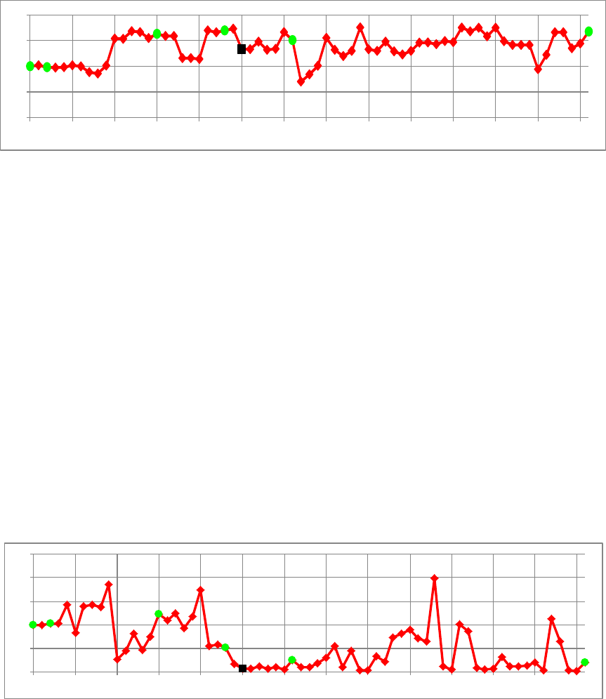
While spot diameter is both interesting and important, it is still a secondary measure of
performance. Effective SSA telescopes should be evaluated based on sensitivity and search rate.
In figure 11, we present the sensitivity of the telescopes for detection of a target that is moving
across the focal plane at a relative rate of 15 arc seconds per second. Many factors combine to
produce this value. The data are presented in relative terms. The plotted value represents the
difference in sensitivity between any given system and the SST. Systems with a positive value
are more sensitive than the SST, while systems with a negative value are less sensitive than the
SST.
Fig. 11. Relative sensitivity given as the difference in visual magnitude relative to the SST.
0.0
1.0
2.0
3.0
4.0
5.0
6.0
7.0
1 6 11 16 21 26 31 36 41 46 51 56 61 66
-3.0
-2.5
-2.0
-1.5
-1.0
-0.5
0.0
0.5
1.0
1 6 11 16 21 26 31 36 41 46 51 56 61 66
-3.0
-2.5
-2.0
-1.5
-1.0
-0.5
0.0
0.5
1.0
1 6 11 16 21 26 31 36 41 46 51 56 61 66

Distribution A: Approved for Public Release, Distribution Unlimited
17
In figure 11, it is interesting to note that the SST, system number 1, and the flat field SST,
system number 3, exhibit essentially identical sensitivity. This result suggests that a curved focal
surface is not essential for making a sensitive, wide-field SSA telescope.
7.4 Search Rate versus Sensitivity
The sensitivity data presented in figure 11 are useful, but the real measure of a telescope
designed for space surveillance is the combination of high sensitivity with high search rate. The
combination of these two characteristics is the problem SST was intended to solve. In this
section, we examine the combination of sensitivity and search rate for all 67 systems.
In figure 12, we plot relative sensitivity taken from figure 11, against normalized search rate
taken from figure 3, for all 67 systems. We have highlighted the SST with the red square to
make it easy to find, but by definition, it would be plotted at a normalized search rate of one and
a relative sensitivity of zero. GEODSS is shown for reference as a green triangle. All other
systems are shown without unique identification. What is important in figure 12 is to note the
position of various systems relative to the SST. The ideal system would be above and to the
right of the SST, but this space we find to be essentially empty. With only slight exceptions, the
existing SST provides an exceptional combination of sensitivity and search rate. There are
however, systems that fall either directly above the SST, indicating greater sensitivity with a
similar search rate, or directly to the right of the SST indicating a similar sensitivity with a
greater search rate. While the SST is an exceptional system, there are alternative telescope
designs that can provide SSA capabilities comparable to those provided by the SST.
Unfortunately, this plot does not include cost data. When comparing systems of similar
performance, cost should be a part of the decision calculus.
Fig. 12. System utility shown as relative sensitivity
plotted against normalized search rate.
-3
-2.5
-2
-1.5
-1
-0.5
0
0.5
1
0.0 0.5 1.0 1.5 2.0 2.5 3.0 3.5 4.0
Relative Sensitivity
Normalized Search Rate
Sensitivity VS Search Rate
Other Systems
SST
GEODSS

Distribution A: Approved for Public Release, Distribution Unlimited
18
As individual data points in figure 12 are somewhat difficult to identify, figure 13 presents a
reduced dataset, including only those systems that we believe should be seriously considered as
potential alternatives to the SST in any future SSA acquisitions. There are a few systems with a
small advantage over the SST in one measure of performance or the other, and only a few
systems that exceed SST performance in both measures, but the differences are essentially
insignificant. Without simultaneous cost data, overall cost versus performance trends cannot be
evaluated. System number 3, the flat field SST has performance virtually identical to the SST
and is plotted underneath the SST red square.
Fig. 13. System utility for a subset of the 67 systems, shown
as relative sensitivity plotted against normalized search rate.
7.5 Performance of Select Systems
Previously we identified six systems we wanted to track through the presentation of data. These
included system numbers 1, 3, 16, 24, 32 and 67. Here we are omitting system number 26,
GEODSS, as it was only included as a reference.
In figure 14, we plot the performance of system numbers 1, 16, 24, 32 and 67 in terms of relative
sensitivity and normalized search rate. System number 3 is not plotted as its performance is
virtually identical to that of the existing SST as mentioned above.
-0.3
-0.2
-0.1
0
0.1
0.2
0.3
0.4
0.25 0.50 0.75 1.00 1.25 1.50
Relative Sensitivity
Normalized Search Rate
Sensitivity VS Search Rate
Comparable Systems
SST

Distribution A: Approved for Public Release, Distribution Unlimited
19
Fig. 14. Performance plots for four systems plus SST.
The results shown in figure 14 deserve close inspection. The 3.6-meter telescope (system
number 16) is physically longer than SST and therefore has an expected greater settle time. It is
more sensitive but slower to search the sky. The estimated cost for this system is in the range of
$42.5M to $103.2M.
The 2.9-meter telescope (system number 24) was designed to achieve SST-level performance
and it essentially accomplishes that task with slightly greater sensitivity and a slightly lower
search rate. It is quite possible that this design would actually have a higher search rate, as the
telescope is expected to have a lower mass and should settle faster than SST, but such a
determination would require a more detailed analysis. The estimated cost range for this system
is $21.9M to $56.3.
The 2-meter telescope (system number 67) has a slightly higher search rate than the SST but is
approximately 0.55 magnitudes less sensitive, a direct result of its smaller size. The estimated
cost range for this system is $8.5M to $20.6. Even with the high cost estimate, this system is
only one-fifth the cost of the SST and provides most of the SSA performance.
The 1.5-meter telescope (system number 32) performs well but struggles in performance
compared to the SST. It is simply too small to be considered as a serious alternative to the SST.
This system is estimated to cost in the range of $3.7M to $9.5M a copy.
All the results presented thus far have relied on the step and stare mode of operation and frame to
frame comparisons to find targets of interest. An experimental processing technique is currently
being developed at the University of New Mexico. The details are not presented here but the
basis of the technique treats image noise differently, thereby allowing one to extract higher
magnitude targets at similar signal to noise ratios as conventional processing. When applying
these experimental algorithms to the four alternative designs plotted in figure 14, we find that
both sensitivity and search rate improve significantly. These results are shown in figure 15. We
see the performance of the SST remains unchanged. This is a result of not applying the
experimental image processing technique to SST images, as we did not have sufficient
Relative Limiting Magnitude (DV
m
)
Normalized Search Rate
-1.2
-1
-0.8
-0.6
-0.4
-0.2
0
0.2
0.4
0.6
0.8
0.8 0.9 1.0 1.1 1.2 1.3 1.4 1.5 1.6
1.5m
2.0m
2.9m
3.6m
Existing
SST
Better

Distribution A: Approved for Public Release, Distribution Unlimited
20
information regarding SST operations and image processing to assess application of this
technique to SST data products.
Fig. 15. Performance of four select systems using the experimental
data processing technique. SST performance predicted using
standard data processing techniques.
In figure 15, we see that the performance of the 2-meter telescope (system number 67) now
exceeds that of the SST and the 2.9-meter design (system number 24) has moved up and to the
right, clearly exceeding current SST performance. The results shown in figures 14 and 15
suggest that telescopes smaller than the SST can equal its performance.
7.6 Cost Data
Results of the simplified cost model are plotted in figure 16. Actual costs for several systems
have been circled for reference. Both the Discovery Channel Telescope (DCT) and VISTA costs
were predicted closely by the lower bound cost model while PanStarrs-1 was better predicted by
the upper bound cost model.
DCT represents a rather interesting data point for the study. The DCT project developers
recently provided detailed insight into their total system cost (from shovel to images) [32].
While the program did experience some cost growth, the DCT is actually a model for an
efficiently executed, cost effective telescope development program. Their costs were very
reasonable given the aperture size, field of view, and design and development of numerous
instruments. The final cost for a turn-key DCT system falls almost perfectly on our lower bound
cost curve.
Normalized Search Rate
-1.2
-1
-0.8
-0.6
-0.4
-0.2
0
0.2
0.4
0.6
0.8
0.8 0.9 1.0 1.1 1.2 1.3 1.4 1.5 1.6
1.5m
2.0m
2.9m
3.6m
Relative Limiting Magnitude (DV
m
)
Improved Data
Reduction Techniques
Existing
SST
Better

Distribution A: Approved for Public Release, Distribution Unlimited
21
Fig. 16. Range of costs as predicted by the simplified cost model.
The data suggest that system numbers 24 and 67 are realistic and affordable alternatives to the
SST. Using either cost model, both of these systems are substantially less expensive than the
SST. This is an important point to stress. System number 24 can equal SST performance using
the same image processing as the SST. Even if one uses the high cost model, system number 24
should cost roughly half the amount required to replicate the existing SST. System number 67 is
much smaller at only 2.0-meters. Simulations suggest this system can equal SST performance
with use of the experimental processing technique. Even when using the high cost model, this
system is predicted to cost only $20.6M. With the experimental processing, system number 67
appears to offer the Air Force an affordable option for acquiring a complete world-wide network
of SSA telescopes.
8. Approaches Not Considered in Current Study
In this study, we examined only a single deep-space SSA problem and a single detection
approach. The SST and any of the 66 other designs considered could be used for detection of
objects in other high altitude orbits, or geosynchronous transfer orbits. There are also other
image collection and data analysis approaches that could be used for SSA. Due to time
constraints, none of these other possibilities were considered. One option that should be
considered would be to operate telescopes in a time-delay integration (TDI) mode where the
telescopes are swept across the sky to image areas. Some initial simulations of this technique
were tried with promising results but were not fully explored. This approach eliminates the need
for a telescope mount that can move and settle quickly. A mount that moves at a lower rate but
with a smooth continuous motion is required.
The TDI approach is presently being investigated in detail by AFRL for inclusion on their Maui-
based 1.2-meter telescope. A special CCD focal plane array specifically designed for multi-stage
TDI is under development and should begin testing sometime during Fiscal Year 2014. This
0
20
40
60
80
100
120
140
160
1 6 11 16 21 26 31 36 41 46 51 56 61 66
Millions of Dollars
VISTA
DCT
PanStarrs
0
20
40
60
80
100
120
140
160
1 6 11 16 21 26 31 36 41 46 51 56 61 66
Millions of Dollars
VISTA
DCT
PanStarrs
Distribution A: Approved for Public Release, Distribution Unlimited
22
telescope, without the TDI capable CCD camera, was included in the above analyses as system
number 40.
9. Conclusions
The results of our informal, unsolicited, academic examination of potential alternatives to the
SST clearly indicate that the current SST design is only one of a number of viable approaches to
achieving a highly sensitive, high search rate system for ground-based optical SSA. In
particular, designs using telescopes with prime focus corrector optics perform extremely well.
These preliminary results could be used to inform senior governmental leaders responsible for
procuring and operating telescopes for SSA, and may provide an initial baseline for a more
detailed and thorough Air Force-sponsored study that would explore a broad range of
alternatives and carefully evaluate sensitivity, search rate, and cost for a variety of viable ground-
based, optical SSA systems. Additionally, when considering the cost of moving the current SST
from its location in New Mexico to a more relevant observing site, we suggest it is prudent to
weigh those costs against the cost to procure potentially more affordable systems that can be
located at a large number of advantageous sites around the world. The results of this study
suggest that the Air Force might procure a smaller aperture system with SSA performance
similar to the SST for a cost comparable to that of moving the SST. Such an option would result
in two very capable SSA systems rather than a single SST at a more favorable location.
Furthermore, this option could avoid an empty building remaining in New Mexico and any
associated site remediation costs.
References
[1] SST Fact Sheet, DARPA,
http://www.darpa.mil/uploadedImages/Content/Our_Work/TTO/Programs/SST/FactSheetTabFinal.JPG, accessed
August 2013.
[2] SST Fact Sheet, DARPA,
http://www.darpa.mil/uploadedImages/Content/Our_Work/TTO/Programs/SST/FactSheetTabFinal.JPG, accessed
August 2013.
[3] Space Surveillance Telescope (SST) Data Sheet, Version 1.0, DARPA, September 2011.
[4] Paul, M., M. Systèmes correcteurs pour réflecteurs astronomiques, Revue d’optique théorique instrumentale,
Vol. 14, No. 5, p. 169 (1935).
[5] Willstrop, R.V., The Mersenne-Schmidt - A three-mirror survey telescope, Monthly Notices of the Royal
Astronomical Society, Vol. 210, p. 597-609 (1984).
[6] Grayson, T.P., Curved Focal Plane Wide Field of View Telescope Design, SPIE Vol. 4849 (2002).
[7] Blake, T., Space Surveillance Telescope, A new generation for ground-based space situational awareness,
DARPA pamphlet, 2011.
[8] Woods, D.F., et al., Space Surveillance Telescope: focus and alignment of a three mirror telescope, Optical
Engineering, Vol, 52, No. 5 (May 2013).
[9] Maloney, J., Space Surveillance Telescope, L-3 Communications public presentation, Albuquerque NM (2011).
[10] Blake, T., Space Surveillance Telescope, A new generation for ground-based space situational awareness,
DARPA pamphlet, 2011.
Distribution A: Approved for Public Release, Distribution Unlimited
23
[11] Liu, R., DARPA’s Expensive Telescope Tracks Space Debris, Keeps Satellites Safe, PhysOrg, April 26
th
,
2011.
[12] Zakaib, G.W., Telescope will track space junk, Nature, Published online 22 April 2011.
[13] SST Fact Sheet, DARPA,
http://www.darpa.mil/uploadedImages/Content/Our_Work/TTO/Programs/SST/FactSheetTabFinal.JPG, accessed
August 2013.
[14] Maloney, J., Space Surveillance Telescope, L-3 Communications public presentation, Albuquerque NM
(2011).
[15] Grayson, T.P., Curved Focal Plane Wide Field of View Telescope Design, SPIE Vol. 4849 (2002).
[16] Blake, T., Space Surveillance Telescope, A new generation for ground-based space situational awareness,
DARPA pamphlet, 2011.
[17] Monet, D., Rapid Cadence Collections with the Space Surveillance Telescope, proceedings of the 2012 AMOS
Technical Conference.
[18] Space Surveillance Telescope (SST) Data Sheet, Version 1.0, DARPA, September 2011.
[19] Space Surveillance Telescope (SST) Data Sheet, Version 1.0, DARPA, September 2011.
[20] Ackermann, M.R., Blind Search for Micro Satellites in LEO: Optical Signatures and Search Strategies,
proceedings of the 2003 AMOS Technical Conference.
[21] Shell, J.R., Optimizing Orbital Debris Monitoring with Optical Telescopes, proceedings of the 2010 AMOS
Technical Conference.
[22] Gao, X., 低轨微小卫星及小碎片搜索辕跟踪机动式大视场光电望远镜 (Mobile telescope with large FOV
for searching and tracking low-orbit micro-satellites and space debris), Chinese Optics, Vol. 4 (2) (2011).
[23] Nemiroff, R.J., Astronomical Journal, 125:2740–2749, 2003 May.
[24] Lambour, R.L., et al., Simulation and Testing of Deep Space Search with the ETS 36-cm Telescope, 2009
US/Russia Space Surveillance Workshop.
[25] Lambour, R.L., et al., Simulation and Testing of Deep Space Search with the ETS 36-cm Telescope, 2009
US/Russia Space Surveillance Workshop.
[26] Brinton, T., DARPA Space Telescope Will Track Objects in Geostationary Orbit, Space News, April 29, 2011.
[27] van Belle, G., The Scaling Relationship Between Telescope Cost and Aperture Size for Very Large
Telescopes, SPIE Vol. 5489 (2004). Reported in CY2003 dollars. Inflates to approximately $56M in CY2012
dollars.
[28] Whitford, A.E., GROUND-BASED ASTRONOMY, A TEN-YEAR PROGRAM, National Academy of
Sciences-National Research Council, Washington DC (1964).
[29] Meinel, A.B., COST SCALING LAWS APPLICABLE TO VERY LARGE OPTICAL TELESCOPES, SPIE,
Vol. 179 (1979).
[30] Computing Exposure Times with the IRAF Task CCDTIME, http://www.noao.edu/gateway/ccdtime/, accessed
August 2013.
[31] Tonry, J.L., Pan-STARRS, ATLAS and optical transient searches, Phil. Trans. R. Soc. Vol. 371, (April 2013).
[32] Discovery Channel Telescope project team, personal communication, August 2013.
