
14:45 – 15:30Questions and answers10
14:15 – 14:45Market information tool9
14:00 – 14:15Coffee8
13:00 – 14:00ACER’s decision on the LT CCM and amendment process of the DA/ID CCM7
12:00 – 13:00Lunch6
11:30 – 12:00Implementation timeline (NorCap) 5
11:15 – 11:30Coffee4
10:15 – 11:15Recap of the FB methodology 3
10:00 – 10:15Status update: where do we come from and where are we now2
09:30 – 10:00Coffee1
Table of Contents

Where do we come from and where are we now?
❖Initial work on the Nordic FB methodology started as a voluntary and joint effort of
all Nordic TSOs in 2012/13.
❖With the CACM entering into force in 2015, the Nordic FB project was altered into
the Nordic CCM project – being a CACM (and FCA) GL implementation project,
addressing all the legal requirements
Nordic LT, DA, ID CCM development
Nordic CCM implementation
2017
2012/
2013
Nordic FB
methodology
development
2015
CACM

Where do we come from and where are we now?
- Nordic LT, DA, ID CCM development and approval -
2018 2020
2018 2019 2020
DA/ID CCM (version 3)
amendment process
DA/ID CCM (version 1) approved
Jul 16
FCA CCM submission
Jan 16
FCA CCM ACER referal
May 15
DA/ID CCM RfA (DUR, EI, EV)
Dec 20
DA/ID CCM (version 2) submitted by ENDK,
FG, and Svk
Jun 20
FCA CCM ACER decision
Oct 30
DA/ID CCM (version 2) approved by DUR,
EI, EV

Where do we come from and where are we now?
- FB simulations -
❖Prototype tools and a prototype CGM have been developed in order to perform an impact
assessment (presented in the supporting document that is published on the Nordic RSC
website: link) and with the objective to run a weekly simulation process
✓ FB capacity calculation and allocation simulations have been performed and are available on the
Nordic RSC website for download (link)
• 17 weeks in 2016
• 11 weeks in 2017
✓ The prototype-based CGM – and thereby the prototype simulation process - is error-prone
• The CGM is built up from individual SCADA models created by each TSO, and merged centrally
• The fact that the SCADA systems were upgraded or replaced at most TSOs stalled the prototype CGM process
to a large extent in 2018/19
❖The prototype simulation process facilitated a learning-by-doing, that is reflected in the IT
specifications of the industrial tool that is currently being implemented
❖The main focus is now on starting the simulations using the industrial tools and industrial
CGMs, during the so-called internal and external parallel runs that are scheduled to start in
2020

Where do we come from and where are we now?
- internal and external parallel run -
The internal and external parallel runs are expected to start in 2020
❖Internal parallel run
✓Testing of the tools and the CGMs available
✓RSC and TSOs to perform the FB capacity calculation
✓TSO to perform the FBMC simulations on an ex-post basis
✓Readiness for the external parallel run
2019 2022
Jul Oct 2020 Apr Jul Oct 2021 Apr Jul Oct 2022 Apr
DA / ID CCM implementation
External parallel run
Amendment process DA/ID CCM ("version 3")
Internal parallel run
ACER decision on LT CCM
Oct 30
Nordic DA / ID CCM Go-liveStart of external parallel run

Where do we come from and where are we now?
- internal and external parallel run -
❖External parallel run (at least for a one-year period)
✓ RSC and TSOs to perform the FB capacity calculation on day-by-day basis (in addition to the
operational NTC capacity calculation process)
✓ NEMOs to perform the FBMC simulations on a day-by-day basis
• Using Euphemia
• Using the operational NTC-world order books
✓ Share the results with the stakeholders
✓ Monitor the KPIs / go-live criteria
✓ Finetune where needed, and have more and more-developed IT modules installed along
the run
2019 2022
Jul Oct 2020 Apr Jul Oct 2021 Apr Jul Oct 2022 Apr
DA / ID CCM implementation
External parallel run
Amendment process DA/ID CCM ("version 3")
Internal parallel run
ACER decision on LT CCM
Oct 30
Nordic DA / ID CCM Go-liveStart of external parallel run
14:45 – 15:30Questions and answers10
14:15 – 14:45Market information tool9
14:00 – 14:15Coffee8
13:00 – 14:00ACER’s decision on the LT CCM and amendment process of the DA/ID CCM7
12:00 – 13:00Lunch6
11:30 – 12:00Implementation timeline (NorCap) 5
11:15 – 11:30Coffee4
10:15 – 11:15Recap of the FB methodology 3
10:00 – 10:15Status update: where do we come from and where are we now2
09:30 – 10:00Coffee1
Table of Contents


Capacity calculation
From complexity to simplicity
Capacity calculation is the
process of translating the
complex physical grid into a
simplified form that can be
understood and applied by the
power exchange
Complexity
Simplicity
Flow
Based
(FB)
Net
Transmission
Capacity (NTC)
Detailed
grid
model
The physical world The commercial world


Guideline on Capacity Allocation and Congestion Management
(CACM GL)
❖ Article 20.2:
‘No later than 10 months after the approval of the proposal for a capacity calculation region in
accordance with Article 15(1), all TSOs in each capacity calculation region shall submit a proposal for
a common coordinated capacity calculation methodology within the respective region.’
❖ The ACER decision on the TSO’s proposal for the determination of Capacity Calculation Regions
dates November 17, 2016
Source: http://eur-lex.europa.eu/legal-content/EN/TXT/PDF/?uri=CELEX:32015R1222&from=EN

Guideline on Capacity Allocation and Congestion Management
(CACM GL)
‘There are two permissible approaches when calculating cross-zonal capacity: flow-based or based on
coordinated net transmission capacity. The flow-based approach should be used as a primary approach
for day-ahead and intraday capacity calculation where cross-zonal capacity between bidding zones is
highly interdependent.’
…
‘The coordinated net transmission capacity approach should only be applied in regions where cross-zonal
capacity is less interdependent and it can be shown that the flow-based approach would not bring added
value.’
Source: http://eur-lex.europa.eu/legal-content/EN/TXT/PDF/?uri=CELEX:32015R1222&from=EN


An example three-node network:
NTCs
A B
C
NTC(A>B) = 750 MW
NTC(B>C) = 750 MWNTC(A>C) = 750 MW
▪ Given the maximum export of bidding area A,
the TSO needs to split the 1500 MW export
capability into two bilateral exchanges, for
example:
▪ NTC(A>B) = 750 MW
▪ NTC(A>C) = 750 MW
▪ There are in principle an infinite number of NTC
solutions; it is a choice which one to select
▪ NTCs are determined by the TSOs to facilitate the market while
safeguarding the grid
▪ A NTC limits a commercial exchange between two bidding areas
▪ NTCs are simultaneously feasible


An example three-node network:
NTC domain
▪ The NTCs in the three-node system define the NTC domain:
the import/export positions that the market is allowed to reach under the market coupling
while not jeopardizing the grid security
A B
C
NTC(A<>B) = 750 MW
NTC(B<>C) =
750 MW
NTC(A<>C) =
750 MW
NTC constraints NTC domain
Net balance A
Net balance B
1000
1000
1500
-1000
-1500
-1500
Max export A
Max import A
Max export BMax import B
Max import C
Max export C
1500
-1000

An example three-node network:
FB constraints
▪ FB constraints are a kind of simplified grid model, reflecting the impact of import/export
positions on the flows on the grid
FB constraints (‘grid model’):
Line Maximum
flow
Influence
from area A
Influence
from area B
Influence
from area C
A>B 1000 MW 33 %
B>C 1000 MW 33 %
A>C 1000 MW 67 %
Margins
PTDF factors
A B
C
+100 MW
-100 MW
67 MW
33 MW

An example three-node network:
FB constraints
▪ FB constraints are a kind of simplified grid model, reflecting the impact of import/export
positions on the flows on the grid
FB constraints (‘grid model’):
Line Maximum
flow
Influence
from area A
Influence
from area B
Influence
from area C
A>B 1000 MW 33 % - 33 %
B>C 1000 MW 33 % 67 %
A>C 1000 MW 67 % 33 %
Margins
PTDF factors
A B
C
+100 MW
-100 MW
67 MW
33 MW

An example three-node network:
FB constraints
▪ FB constraints are a kind of simplified grid model, reflecting the impact of import/export
positions on the flows on the grid
FB constraints (‘grid model’):
Line Maximum
flow
Influence
from area A
Influence
from area B
Influence
from area C
A>B 1000 MW 33 % - 33 %
0
B>C 1000 MW 33 % 67 %
0
A>C 1000 MW 67 % 33 %
0
Margins
PTDF factors
A B
C
+100 MW
-100 MW

An example three-node network:
FB constraints
▪ FB constraints are a kind of simplified grid model, reflecting the impact of import/export
positions on the flows on the grid
FB constraints (‘grid model’):
Line Maximum
flow
Influence
from area A
Influence
from area B
Influence
from area C
A>B 1000 MW 33 % - 33 %
0
B>C 1000 MW 33 % 67 %
0
A>C 1000 MW 67 % 33 %
0
B>A 1000 MW -33 % 33 %
0
C>B 1000 MW - 33 % - 67 %
0
C>A 1000 MW - 67 % - 33 %
0
Margins
PTDF factors
A B
C

An example three-node network:
FB domain
▪ The FB constraints in the three-node system define the FB domain:
the import/export positions that the market is allowed to reach under the market coupling
while not jeopardizing the grid security
FB domain
Net balance A
Net balance B
1000
1000
1500
-1000
-1500
-1500
1500
-1000
FB constraints
Constrained by B>C
Constrained by A>C
Constrained by B>A
Line Maximum
flow
Influence
from area A
Influence
from area B
Influence
from area C
A>B 1000 MW 33 % - 33 % 0
B>C 1000 MW 33 % 67 % 0
A>C 1000 MW 67 % 33 % 0
B>A 1000 MW - 33 % 33 % 0
C>B 1000 MW - 33 % - 67 % 0
C>A 1000 MW - 67 % - 33 % 0

An example three-node network:
NTC vs FB domain
FB domain
Net balance A
Net balance B
1000
1000
1500
-1000
-1500
-1500
1500
-1000
NTC domain
▪ In FB capacity split is not a choice of the TSO, but is market
driven (at the time of allocation)
▪ In principle, FB offers more trading opportunities with the
same level of security of supply
▪ Example:
▪ NTC: North-South exchange limited to 1500 MW
▪ FB: North-South exchange possible of 2000 MW
A B
C
+750 MW
-1500 MW
A B
C
+1000 MW
-2000 MW
+1000 MW+750 MW
NTC FB

Advantages of the FB approach
▪ In FB capacity split is not a choice of the TSO, but is market driven (at the time of allocation)
▪ More efficient and flexible use of the grid
▪ FB offers more trading opportunities with the same level of security of supply
▪ More price convergence / smaller price differences
▪ Higher social welfare
▪ Income redistribution: Less congestion income and more producer and consumer surplus
▪ FB offers the possibility to have the DC cables efficiently embedded in the allocation mechanism,
by providing a fair competition for the use of the scarce AC capacity
▪ Flow-based market coupling provides an efficient allocation mechanism in which all exchanges
that are subject to the allocation mechanism compete with one another for the use of the scarce
capacity

An example three-node network:
DC links - Advanced Hybrid Coupling
Line Maximum
flow
Influence
from area A
Influence
from area B
Influence
from area C
Influence from
virtual BZ
A>B 1000 MW 33 % …
…
45%
B>C 1000 MW 33 % …
…
45%
A>C 1000 MW 67 % …
…
55%
B>A 1000 MW … …
… …
C>B 1000 MW … …
… …
C>A 1000 MW … …
… …
Margins
PTDF factors
A B
C
+100 MW
-100 MW
55 MW
45 MW
DC
Virtual
Bidding Zone
▪ Advanced Hybrid Coupling is applied on all DC links and AC connections to other CCRs
▪ In this way, they compete for the scarce capacity in the AC grid like any other commercial exchange
▪ This introduces virtual bidding zones at the converter stations of the DC links in the Nordic area


Nordic DA CCM in a nutshell
▪ Advanced Hybrid Coupling is applied on all DC links and
AC connections to other CCRs
▪ Number of Bidding Zones: 27
▪ Nordic bidding zones: 12
▪ Virtual bidding zones: 15
▪ Two synchronous areas
▪ DK1 is part of the continental European synchronous
system
▪ Number of presolved FB constraints
▪ Around 85
▪ In order to maximize socio-economic welfare, the FB
market coupling could result in “non-intuitive” flows on
some borders: flows from a high-price to a low-price area


FB simulations: setup
▪ FB simulations are being performed by the project, based on
▪ Prototype CGMs
▪ Prototype tooling to perform the DA FB capacity calculation
▪ The so-called NEMO’s Simulation Facility to simulate the SDAC using the FB constraints and
actual historical order books
▪ With the implementation ongoing at the Nordic RSC, gradually, elements in this process will
be replaced by more robust data and IT modules
DA CGMs
(D-2)
DA capacity
calculation
FB parameters
(PTDFs and RAMs)
DA allocation
(SDAC)

FB simulations: socioeconomic welfare gains
▪ The following results are for weeks 1-6 and 8-12, 2017
and compare the market outcomes with FB and with
historical NTCs.
▪ The graphs show the difference between the day-
ahead socioeconomic welfare (SEW) with FB and with
historical NTCs
▪ Day-ahead SEW = producer surplus + consumer
surplus + congestion income
▪ Structural congestions such as West Coast corridor and
export limitations in Norway dealt with in a more
efficient way with flowbased:
▪ No need to limit capacities ex ante.
▪ Instead: full capacities + critical network
elements given to the market => capacity
allocated in the market in a more efficient way.

Week 1: 4 January, 03.00: A windy night
Example of the West-Coast Corridor
• A lot of wind to be exported
from DK/GE to the Nordics
• With NTC, ex-ante
limitations on DK1->SE3 and
DK2->SE4 due to West Coast
corridor
• With FB, capacity allocation
in the market considers
directly the West Coast
corridor without need for
limitations.
• Note that the limitations GE-
>SE4 are due to limitations
on the German side.

14:45 – 15:30Questions and answers10
14:15 – 14:45Market information tool9
14:00 – 14:15Coffee8
13:00 – 14:00ACER’s decision on the LT CCM and amendment process of the DA/ID CCM7
12:00 – 13:00Lunch6
11:30 – 12:00Implementation timeline (NorCap) 5
11:15 – 11:30Coffee4
10:15 – 11:15Recap of the FB methodology 3
10:00 – 10:15Status update: where do we come from and where are we now2
09:30 – 10:00Coffee1
Table of Contents

Nordic RSC
NorCap implementation timeline
2019.12.12

1. Short introduction
2. NorCap implementation project (Scope)
3. Stepwise implementation
4. Implementation timeline
5. Questions
Presentation
For those of you who don’t know me:
My name is Raini Urbschat
Short introduction
• Procurement lead to support the procurement
of the NorCap IT application
• Project Manager of the NorCap implementation
project
• Employed by Nordic RSC to support the
transition to operation
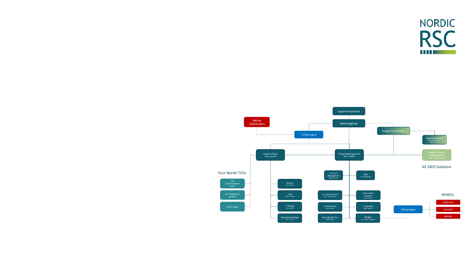
• I’m trying to keep track of this organization
within Nordic RSC ☺ →

NorCap implementation project
Architecture and InfoSec
Integration and Exchange standards
Intraday and Day ahead processes
IGM
CGM
Flowbased
calculation
Capacity/
domain
validation
MIT
PX
IGM
IGM
CNTC
calculation
FRM
TRM
CSA
OPC
Out of scope
NorCap scope
IGM
Release
capacities
IGM = Individual Grid Model
CGM = Common Grid Model
CSA = Coordinated Security Analysis
CNTC = Coordinated NTC
FRM = Flow Reliability Margins
TRM = Transfer Reliability Margins
PX = Power Exchanges
MIT = Market Information Tool
OPC = Outage Planning Coordination

Intraday and Day ahead processes
Architecture and InfoSec
Integration and Exchange standards
IGM
CGM
Flowbased
calculation
Capacity/
domain
validation
MIT
PX
IGM
IGM
CNTC
calculation
FRM
TRM
CSA
OPC
Out of scope
NorCap scope
IGM
Release
capacit
ies
Proof of Concept
CGM Flowbase
Intermediate release
CGM
Allowing us to work
more structured
with Data Quality
Improvement
Major Release 1
CGM Flowbase
Domain
Validation
(Minimal Viable Product)
Major Release 2
CGM Flowbase
Domain
Validation
PX
integration
MIT
(First version of NorCap)
Major Release 3
CSA CNTC
FRM
TRM
Stepwise implementation of
the NorCap IT Application

Implementation timeline (working assumption)
2019 2020 2021
Proof of Concept Intermediate release
Major Release 1
Design Development Test Implementation
Major Release 2
Design Development Test Implementation
Proof of Concept
implemented
2019.06.30
MR1 Design
approved
2019.08.16
Intermediate release
implemented
2019.10.15
MR1 Development completed
2020.02.05
MR2 design completed
2020.01.31
Major Release 3
Design Development Test Implementation
Parallel run start ?

• The number of stakeholders involved
• Implementation of CGMES is still ongoing
• Flowbased methodology is new
• New IT development methods are used
Timeline risks

Any questions

14:45 – 15:30Questions and answers10
14:15 – 14:45Market information tool9
14:00 – 14:15Coffee8
13:00 – 14:00ACER’s decision on the LT CCM and amendment process of the DA/ID CCM7
12:00 – 13:00Lunch6
11:30 – 12:00Implementation timeline (NorCap) 5
11:15 – 11:30Coffee4
10:15 – 11:15Recap of the FB methodology 3
10:00 – 10:15Status update: where do we come from and where are we now2
09:30 – 10:00Coffee1
Table of Contents

Nordic LT, DA, ID CCM development and approval
2018 2020
2018 2019 2020
DA/ID CCM (version 3)
amendment process
DA/ID CCM (version 1) approved
Jul 16
FCA CCM submission
Jan 16
FCA CCM ACER referal
May 15
DA/ID CCM RfA (DUR, EI, EV)
Dec 20
DA/ID CCM (version 2) submitted by ENDK,
FG, and Svk
Jun 20
FCA CCM ACER decision
Oct 30
DA/ID CCM (version 2) approved by DUR,
EI, EV

Original Nordic TSO LT CCM proposal: CNTC
❖In the FCA GL, the CNTC methodology is
the default capacity calculation approach
❖The Nordic TSOs proposed a CNTC LT
capacity calculation methodology, where
✓A linearized security domain (i.e. FB domain is
assessed) first, and
✓A CNTC domain is extracted from that
❖As there are many CNTC domains that can
be extracted from the FB domain, the
CNTC extraction is based on an
optimization
-400
-300
-200
-100
0
100
200
300
400
-400 -300 -200 100 200 300 400-100 0
Exchange(A>C)
Exchange(B>D)
“CNTC”
domain
FB domain
NTC(B>D)
NTC(D>B)
NTC(A>C)
NTC(C>A)

Original Nordic TSO LT CCM proposal: CNTC
❖CNTC characteristics
✓CNTC is a “limited / not-so-detailed” way
to represent grid limitations
✓All CNTC capacities are simultaneously
feasible
❖Due to these characteristics, the fear
is that the CNTC domain, that is
extracted from a FB domain, is too
restrictive (compared to today’s
values)
❖Therefore, relaxation of the FB
domain is considered for the CNTC
extraction
✓This comes at a price: the CNTC domain
“sticks” out of the FB domain and may
cause an operational risk.
-400
-300
-200
-100
0
100
200
300
400
-400 -300 -200 100 200 300 400-100 0
Exchange(A>C)
Exchange(B>D)
CNTC
domain
FB domain
Base case


ACER’s decision on the Nordic LT CCM: FB
❖On May 15, Nordic NRAs referred the LT CCM to ACER
✓NRAs have a different interpretation of “what constitutes a CNTC and what
constitutes a FB methodology”
❖ACER amended the LT CCM, and iterated with TSOs and NRAs in weekly
conference calls
❖ACER decided on October 30 (Decision 16/2019) to approve the Nordic LT
CCM (see embedded documents FYI)
❖ACER decided on a FB Nordic LT CCM:

ACER’s decision on the Nordic LT CCM: FB
some highlights
ACER decision
❖ FB
FB with ATC extraction as intermediate solution
until a FB LT allocation is supported by the service
provider (the terminology CNTC is not used)
❖ Optimization-based CNTC extraction (unchanged)
❖ Dynamic constraints as allocation constraints
This means that the dynamic analysis can be
performed by the TSO
❖ Advanced hybrid coupling is part of the CCM
(unchanged)
❖ Publication of data has been extended and
aligned to that of the ACER decision on the Core
DA/ID CCM
Original Nordic TSO proposal
❖ CNTC
A linearized security domain (i.e. FB domain is
assessed) first, and a CNTC domain is extracted
from that
❖ Optimization-based CNTC extraction
❖ Dynamic constraints as CNEs (as so-called PTCs:
Power Transfer Corridors)
This means that the dynamic analysis can be
performed by the TSO
❖ Advanced hybrid coupling is part of the CCM
❖ Publication of data as in the Nordic DA/ID CCM

ACER’s decision on the Nordic LT CCM: FB
some highlights
Amendment of the LT CCM / actions required within 18 months after implementation
of the methodology
❖Amend the CCM by including the method for assessing the economic efficiency of
including internal network elements (combined with the relevant contingencies) in
the long-term capacity calculation.
❖Amend the CCM - in case the concerned Nordic TSOs cannot find and implement a
more efficient solution than the applied combined dynamic constraint - by:
(a) the technical and legal justification for the need to continue using the combined
dynamic constraint indicating the underlying operational security limits and why they
cannot be transformed efficiently into maximum flow on specific CNECs;
(b) a detailed methodology to calculate the values of the combined dynamic
constraints.
❖Amend the CCM by further harmonizing the generation shift key methodology.
❖Amend the CCM by including the description and definition of the functions used in
the ATC extraction.

Amendment process of the DA/ID CCM
❖The “Version 2” DA/ID CCM - being the amended DA/ID
CCM following the RfA from DUR, EI, and EV – has been
approved by the three NRAs
❖The Nordic TSOs are in the process of amending the DA/ID
CCM (“Version 3”), in line with the LT CCM
❖This amended DA/ID CCM is to replace fully the earlier two
versions
❖The public consultation of this amended DA/ID CCM is
expected to start in January 2020

Amendment process of the DA/ID CCM
Some highlights
❖FB ID, with ATC extraction as intermediate solution until a
FB ID allocation is supported by the service provider
❖Publication of data as proposed by ACER for the LT CCM
❖Dynamic constraints as allocation constraints
❖18 months after DA/ID CCM implementation, amend the
CCM by including the method for assessing the economic
efficiency of including internal network elements
❖Economic efficiency test and operational security test for
the application RAs will be removed in the light of the
previous bullet, and the Regulation 943/2019

14:45 – 15:30Questions and answers10
14:15 – 14:45Market information tool9
14:00 – 14:15Coffee8
13:00 – 14:00ACER’s decision on the LT CCM and amendment process of the DA/ID CCM7
12:00 – 13:00Lunch6
11:30 – 12:00Implementation timeline (NorCap) 5
11:15 – 11:30Coffee4
10:15 – 11:15Recap of the FB methodology 3
10:00 – 10:15Status update: where do we come from and where are we now2
09:30 – 10:00Coffee1
Table of Contents

MIT, Background
❖ The interpretation of this has been discussed in previous stakeholder
meetings
❖ Capacity data will be made available on a web platform, available at the start
of ||-run
❖ The platform will support three means of accessing data;
1. Through web browser
2. Through download of excel file(s)
3. Through Application Programmable Interface (API) – “machine-to-machine”
CACM, Art. 20


MIT Development
❖ MIT will be released in phases (as similiar to the entirety of the implementation)
❖ R1 will not contain any CNTC calculations (or presenting FB domain as ATC)
❖ Release 2 (R2) will make available both CNTC representation of DA FB domain,
as well as starting ID CNTC domain
❖ Future discussion will be held on what to be published on ”Nordic MIT” and on
”European Transparency Platform”
MR1
•TSO integration
•FB release 1
MR2
•NEMO integration
•FB release 2
•MIT release 1
•Start of ||-run
MR3
•CNTC
•MIT release 2
Go-live
•DA: Flow based
•ID: CNTC


MIT Data, General Domain information
Information
MR1
MR2
MR3
Base
case net positions
✓*
Min/max
possible net positions
✓
FB domain transformed into CNTC parameters
✓
Min/Max bilateral
exchange
✓
GSK strategies used for each BZ
✓
Allocation Constraints, with constraining TSO
✓
Indication of whether results stem from fallback (or
extrapolation)
✓
* Will be published ex-post, with a delay of 7 days

MIT Data, CNEC data per MTU (FB Domain)
Information Description MR1 MR2
Sending TSO The TSO that has submitted the constraint
✓
CNEC Name The name of the constraint
✓*
CNE Name The name of the critical network element that is monitored
✓*
Contingency Name The name of the contingency that is studied (if any)
✓*
From/To BZ
The bidding zones of each terminal of the critical network
element
✓
RAM (MW) Remaining Available Margin
✓
RAM (% of Fmax)
Remaining Available Margin as percentage of Maximum
admissible flow
✓
FRM (MW) Flow Reliablity Margin
✓
Fref (MW) Reference flow in base case CGM
✓**
Fref’ (MW) Linearized reference flow, adjusted to zero net positions
✓
FAV (MW) Final Adjustment Value (operator adjustment)
✓
RA (MW) The increased amount of capacity given from remedial action(s)
✓
Fmax (MW) Maximum admissible physical flow
✓
F_AAC (MW)
Flow on element, due to already allocated capacity in a previous
timeframe
✓
PTDF for each BZ Power Transfer Distribution Factors
✓
** Will be published ex-post, with a delay of 7 days
* Will only be published for Energinet & Fingrid data,
due to security laws in Sweden & Norway

14:45 – 15:30Questions and answers10
14:15 – 14:45Market information tool9
14:00 – 14:15Coffee8
13:00 – 14:00ACER’s decision on the LT CCM and amendment process of the DA/ID CCM7
12:00 – 13:00Lunch6
11:30 – 12:00Implementation timeline (NorCap) 5
11:15 – 11:30Coffee4
10:15 – 11:15Recap of the FB methodology 3
10:00 – 10:15Status update: where do we come from and where are we now2
09:30 – 10:00Coffee1
Table of Contents
