
FISHER MANSION HISTORIC
STRUCTURE REPORT
FEBRUARY 05, 2010

ARCHITECTURE
PLANNING
INTERIORS
649 E SOUTH TEMPLE
SALT LAKE CITY, UT 84102
801.355.5915
www.crsa–us.com

TABLE OF CONTENTS
INTRODUCTION & EXECUTIVE SUMMARY
BUILDING & SITE DESCRIPTION
EXTERIOR ANALYSIS
FLOOR PLANS & FRAMING PLANS
INTERIOR ANALYSIS
LIFE SAFETY & ACCESSIBILITY
SUSTAINABILITY & LEED
®
CERTIFICATION
STRUCTURAL & BUILDING SYSTEMS ANALYSIS
COST ESTIMATE
. . . . . . . .
. . . . . . . . . . .
. . . . . . . . . . . . . . .
. . . . . . . . . .
. . . . . . . . . . . . . . .
. . . . . . . . . . .
. . . . . . . .
. . . . . .
. . . . . . . . . . . . . . . .
01
02
03
04
05
06
07
08
09
FISHER MANSION HISTORIC
STRUCTURE REPORT
FEBRUARY 05, 2010
SECTION ONE: INTRODUCTION & EXECUTIVE SUMMARY

2
3
Fisher Mansion HSR, February 2010
SECTION ONE: INTRODUCTION & EXECUTIVE SUMMARY
INTRODUCTION
The Fisher Mansion and Carriage House, located on
Salt Lake City’s west side at 1206 West 200 South,
were designed by Richard Kletting and constructed
in 1893 for Albert and Alma Youngberg Fisher. This
Historic Structure Report evaluates the historic ele-
ments of these two buildings, their potential options
for future preservation and re-use, and requirements
a ecting their re-use. Numerous suggestions for new
uses of the buildings have been made since Salt Lake
City made the decision to retain the property, which
was purchased in 2006 for the purposes of extending
the Jordan River Parkway. The processes and results
of this report are intended to advance the task of
nding an appropriate and viable re-use for the prop-
erty that respects the character of these signi cant
historic structures.
It is the intent that, at a minimum, any re-use proj-
ect for the property will meet the Secretary of the
Interior’s Standards for the Treatment of Historic
Properties with Guidelines for Preserving, Rehabilitat-
ing, Restoring and Reconstructing Historic Buildings
(SOTIS). The following information from the National
Park Service website, gives a brief summary of the
standards for the four treatments.
“The Standards for the rst treatment, Preservation,
require retention of the greatest amount of his-
toric fabric, along with the building’s historic form,
features, and detailing as they have evolved over
time. The Rehabilitation Standards acknowledge the
need to alter or add to a historic building to meet
continuing or new uses while retaining the building’s
historic character. The Restoration Standards allow for the
depiction of a building at a particular time in its history
by preserving materials from the period of signi cance
and removing materials from other periods. The Recon-
struction Standards establish a limited framework for re-
creating a vanished or non-surviving building with new
materials, primarily for interpretive purposes.”
METHODOLOGY
This report builds upon a Historic Structure Report done
in 2008 for Salt Lake City Corporation by students from
the University of Utah College of Architecture and Plan-
ning. Information and documentation from the U of U
HSR have been incorporated into this report. In some
sections the information was incorporated directly with
minor updates, while other sections include additional
information, modi cations, and updates that have re-
sulted from the consultant team’s opportunity to conduct
more in-depth and hands-on investigations and analyses
of the buildings and site.
In general, the narrative of this report is presented in
a three-part format with Historical Data and a short
description of each building system or component
presented rst, followed by an analysis of the Existing
Condition(s) and concluding with Recommendations.
Recommendations are presented for two treatment
approaches to the building – that of a preservation ap-
proach and that of a restoration approach. As speci c
uses for the buildings are identi ed, it is anticipated that
the preservation approach, which serves to protect and
stablize a property until a use and treatment are identi-
ed, may shift into a rehabilitation approach.

4
EXECUTIVE SUMMARY
CONTEXT
Architect Richard K.A. Kletting designed the Fisher
Mansion and Carriage House for Albert and Alma
Youngberg Fisher, located adjacent to the Jordan River
on 200 South Street. Proximity to work is assumed
to be the driving factor behind the Fisher’s locat-
ing their residence in what was a sparsely populated
neighborhood at the time of construction in 1893.
Albert Fisher was the president of the Fisher Brew-
ing Company, which was located at 160 South 1100
West. The neighborhood around the Fisher Mansion
became more populated after the turn of the twentieth
century, with residences lining the streets to the south
and east, though most were of a more moderate scale.
The area to the west and the north, however, saw the
addition of more industrial uses. When Interstate 80
was constructed, all of the homes on the south side
of 200 South were demolished. The Fisher Mansion
became an isolated property, from the physical barrier
of the interstate as well as by its industrial neighbors.
Despite the loss of its neighborhood context, the home
remained inhabited and maintained.
HISTORY OF USES
Prior to its purchase by Salt Lake City, the Fisher Man-
sion went through three distinct periods of use since its
construction in 1893.
Period I: 1893 to 1944
During the rst 51 years, the Fisher family used the
mansion as its original intended use, that of a family
residence. Albert Fisher died in 1917. Alma Youngberg
Fisher, Albert’s wife, continued to live in the home until
her death in 1940. Beginning in about 1918, Alma’s
daughter and son-in-law, Alice Fisher Davidson and
Frederic Davidson, lived in the home with Alma until
her death. After Alma’s death, the title to the property
was transferred to Alice. The Davidson’s remained in
the home until 1944.
Period II: 1945 to 1970
Upon moving out of the home, the Davidson’s leased
the mansion to the Catholic Church beginning in 1945.
From 1945 until 1970 it was used as a convent by Our
Lady Queen of Peace and Our Lady of Victory Mission-
ary Sisters.
Period III: 1970 to 2006
Beginning in 1970 it became St. Mary’s Home for Men,
a residential substance abuse treatment facility. In
1973, Alice Fisher Davidson bequeathed the property
to the Roman Catholic Bishop of Salt Lake City. The
mansion remained in use as St. Mary’s Home for Men
until the property was purchased by Salt Lake City in
2006.
The majority of alterations made to the home were
done in e orts to accommodate a high number of
occupants and meet the associated building code
requirements. During its use as a family residence, it is
notable that is was occupied only by the Fisher family.
Aerial view of Fisher Mansion neighborhood looking
northwest, 1958

5
Fisher Mansion HSR, February 2010
This may have been a signi cant contributing factor to
the minimal amount of interior updates and alterations
during its rst 50-year period. Absent are signs of many
layers of wallpaper and paint, as is often seen in homes
of this age. Initial analysis indicates a single layer of
wallpaper and only two to three layers of paint on most
of the walls.
The Fisher Mansion is remarkable for the high degree
of architectural integrity it retains, especially consider-
ing its history of higher intensity uses over the past 65
years. While several alterations were made to accom-
modate these higher intensity uses, it is clear that, as
lessees and subsequent owners, the Catholic Church
gave a high degree of stewardship and respect to the
property, its history, and its architectural details.
Probable changes made during the initial period of use
as the Fisher family’s home:
Enclosure of small northwest porch (c. 1920s)•
Probable changes made during the second period of
use:
Conversion of the parlor into a chapel for the •
convent
Addition of the rear third story room as ad-•
ditional bedroom space (c. 1940s; addition is visible
in 1950 aerial photo)
Addition of hand rails on rear staircase•
Subdivision of southwest bedroom, second •
oor
Access to butler’s pantry from hallway•
Painting/stenciling of parlor, wallpaper •
painted over
Probable changes made during the third period of use:
Expansion and enclosure of northeast porch•
Addition/expansion of previously enclosed •
northwest porch, which now connects to the north
end of the parlor
Floor tile installed in kitchen, northwest addi-•
tion, and parlor
Updates/remodel of rst oor bathroom, •
second level bathroom
Enclosure of main staircase•
Covering of skylight•
Removal of railing in attic surrounding sky-•
light
SUMMARY OF HISTORICALLY SIGNIFICANT ARCHI
TECTURAL ELEMENTS
Exterior
Brick – unpainted walls•
Sandstone lintels, sills, columns, foundation •
walls, decorative plaques
Stamped metal frieze & ornamental foliation•
Wood eaves •
Wood double-hung windows•
Wood windows with curved glass•
Wood full-length balcony access windows•
Leaded glass transom windows•
Exterior front doors with intact hardware•
Metal doorbell and plate•
Gutter and downspout system•
Porch – sandstone oor, columns, wood deco-•
rative spindles, wood beadboard ceiling, sandstone
support arches
Original dormers on south and west sides•
Corbelled brick chimneys (4)•
Historic view of Fisher Mansion, looking northeast.

6
Interior
Flooring: Ceramic tile oor (entrance vestibule, •
main level bathroom); Oak veneer ooring through-
out main and second levels
Wall nishes: Original plaster and lath; Wood •
wainscoting; Embossed wallpaper (has since been
painted over)
Wood trim: never been painted, original stain; •
Original baseboard, Door casing, Window casing,
Double archway in foyer
Majority of original stile and rail wood panel •
doors
Transoms over doors•
Glass bi-fold doors•
Double doors into vestibule, parlor•
Grand staircase (missing balusters)•
Fireplace mantles and tile surrounds•
Original electric outlets (on parlor replace •
mantle)
Light xtures•
Rear staircase•
Built in cabinets in library•
Metal heating vent covers (majority, some •
missing)
Skylight (missing some panels)•
Sink in main level bathroom•
Pocket door on second level separating family •
space from servant space
Cistern room, glass doors into cistern room•
Removed/Missing Elements
Balcony railing•
Curved glass/leaded glass in transoms of •
southwest bay windows on rst and second levels;
and southeast bedroom on second level
Original windows for attic level•
Original exterior door for northwest entry•
Several interior wood panel doors•
Grand staircase balusters•
Railing/balustrade around skylight on attic •
level
Altered/Updated Elements
Porch: new front steps, side walls; railing (cast •
concrete) – to replace original sandstone, which was
deteriorating
Rear window placement – original butler’s •
pantry was located east of the kitchen; its window
was removed and a new shorter, square window
was inserted at a position shifted west. The brick
was patched well; the lintel of the original window
remains in place.
Transom over northwest doorway (covered, •
likely still intact)
Wallpaper (painted over)•
Second level bathroom (unknown what is •
underneath raised oor)
Suite on second level for housekeeper/domes-•
tic sta
REUSE/RENOVATION CONSIDERATIONS
The objective of re-use strategies will need to balance
several factors, including life safety issues and how to
approach any structural upgrades without compromis-
ing architectural integrity. Some of the structural ap-
proaches described will have adverse e ects on some
of the interior architectural elements. For example, the
installation of diaphragms will a ect the wall-ceiling
areas due to the visability of the connectors if done
on the underside of the joists, or will require removal
of ooring if done on the top of the joists. Yet, the
value of installing these diaphragms is a cost-e ective
approach to improving the structural integrity and
improving life-safety for the building’s occupants.
Additional considerations regarding the degree of ren-
ovation will need to be balanced with desirable uses.
For example, the cost of a full-scale restoration may
not be feasible for a small o ce tenant. Also, a higher
intensity use may not be compatible with the objective
of conducting a full restoration of the interior.
SECTION TWO: BUILDING & SITE DESCRIPTION

8

9
Fisher Mansion HSR, February 2010
half story brick and stone house designed in the Victorian
Eclectic style. Architect Kletting designed the large-scale
house using a combination of materials and decorative
elements. It has maintained its architectural integrity
since its construction in 1893. The overall stylistic and
decorative qualities of the mansion make it one of the
best examples of the more elaborate Victorian Eclectic
residences constructed in Salt Lake City in the last two
decades of the nineteenth century. Located to the rear
of the house is a two-story brick carriage house, also
designed by Kletting in the same style as the house. Both
buildings are situated on a one-acre lot adjacent to the
east bank of the Jordan River.
The house is a combination of the central block
with projecting gables type and the four square type.
While its massing and layout are asymmetrical in nature,
the facade projects an overall sense of balance.
Characteristics of the Eclectic style include a
combination of Victorian and Classical stylistic elements,
BUILDING DESCRIPTION
BACKGROUND
The Fisher mansion was built for Albert
Fisher, a German immigrant who founded the Fisher
Brewing Company in 1884. Of the several breweries
established in Utah in the late 1800s, Fisher Brew-
ing was the only one to return to operation after
the repeal of Prohibition. The brewery continued to
operate under the direction of the Fisher family until
1972.
Richard K. A. Kletting designed the two-story, twelve-
room house that had an estimated construction cost
of $13,000. The Fisher Brewing Company was located
nearby at 160 S. 1100 West and Fisher, who had been
living at the brewery, desired a nearby location for
his home. The site of the home was away from the
crowded central city, located adjacent to the Jordan
River, and provided a view of the Wasatch Mountains
to the east.
The residence is an architecturally and historically
signi cant structure for being an excellent example
of the Victorian Eclectic style in Utah, as well as for its
association with Albert Fisher. It is also signi cant as
one of the relatively few extant residential designs
done by Kletting. First nominated to the National
Register of Historic Places in 1983, but not listed at
the time due to owner objection, the property was
listed in 2008.
ARCHITECTURAL STYLE
The Albert Fisher mansion is a two and one-
SECTION TWO: BUILDING & SITE DESCRIPTION
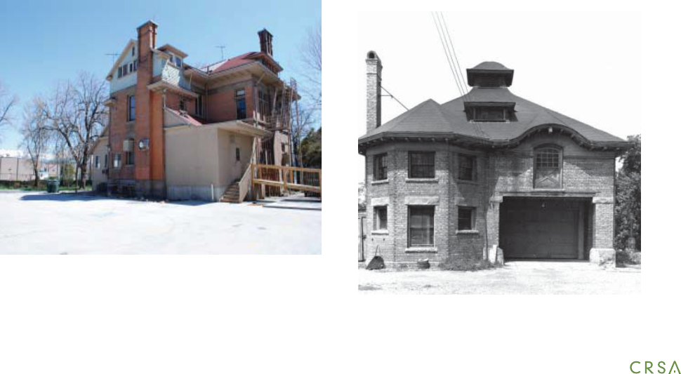
View of the front facade of the Fisher Mansion, prior to
the restoration of the front porch steps.

10
irregular plan, asymmetrical façade and roof form, bay
windows, decorative porches, projecting door and
window lintels, leaded and stained-glass transom win-
dows, and patterned belt courses.
The Fisher Mansion has many of the above character-
istics, yet the design is also notable for showcasing the
massing and lines of the home. Kletting designed the
building on a large scale with an unusual combina-
tion of features and details. Elements of the Queen
Anne appear in the wrap-around porch, which features
Eastlake and Romanesque details as well. The result is
a distinctively unique example of the Victorian Eclectic
style. The carriage house re ects the massing and style
of the house.
LATER ALTERATIONS
While the front facade of the mansion remains
largely unchanged since its construction, the rear of
the mansion has undergone several modi cations. On
the 1911 Sanborn Map, the rear portion of the man-
sion is identifed as being one and one-half stories of
brick with single story wood frame porches on the east
and west sides. Evaluation of the rear (north) chimney
reveals evidence of the original gabled roof line. In the
1940s, likely to provide additional bedroom space for
the convent, a third story room with a shingled exterior
was added. On the main level of the building, the two
rear side porches have been enclosed and expanded.
The roof lines of the original porches are still present in
the larger additions that have encompassed them. The
current porch additions date to 1993, when upgrades
were made, including expansion of the kitchen facili-
ties. The pro le and materials of the third oor addition
View of the rear of the mansion, camera facing southeast
Sketch of the likely original appearance of the
rear of the mansion
Historic photo of Fisher children in front of the mansion
11
Fisher Mansion HSR, February 2010
are similar to the earlier dormers and have attained
historical signi cance of their own.
SITE DESCRIPTION
HISTORICAL DATA & EXISTING CONDITIONS
Over the years the landscape surrounding the Fisher
mansion site has been modi ed to accommodate the
changing use of the building. The original landscape
was once typical of Victorian yards in the Salt Lake
area. The landscape was originally designed with the
purpose of showing o the architecture of the build-
ing, providing climate control for the structure, servic-
ing functional uses for the owners, and for providing
outdoor relaxation and recreation for the building’s oc-
cupants. The aesthetic quality of the landscape would
have originally focused on framing views into and out
of the home. This can be seen in the formal entrance
layout that features a wide sandstone walkway leading
to the front porch. The front-walkway and landscaping
was primarily bilaterally symmetrical along the axis
leading to the front doors. This symmetry was empha-
sized by the placement of two weeping mulberry trees
and two stone spigots placed on either side of the
walkway. These features still exist today. The original
drive access to the building was located on the western
edge of the site, as indicated on the 1911 Sanborn
map. The drive would likely have consisted of concrete
travel strips, macadam, or a compacted crushed stone.
Photographic evidence and on-site archeological inves-
tigations may be used to determine the original layout
and material quality of the original hardscape. By 1950,
a more substantial concrete driveway was in place on
the east side of the property, with a semi-circular drive
providing access to the east porch of the mansion.
This driveway con guration is what currently exists.
Additionally, a signi cant portion of the rear landscape
has been paved to provide more on-site parking. The
locations of paths around the building have also been
altered as additions to the structure have changed
the exterior circulation. A fountain, installed while the
property housed St. Mary’s Home for Men, is located in
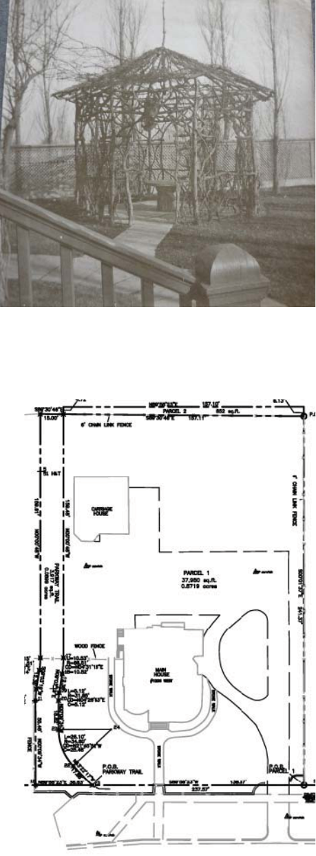
Historic photo of a rustic twig gazebo, located on the
northeast corner of the mansion.
Parcel map indicating location of the Jordan River
Parkway in relation to the site

12
the lawn area east of the carriage house. Historically,
an octogonal rustic twig gazebo was located to the
northeast of the mansion. During the summer months,
foliage growth over the gazebo created a shaded out-
door room.
Hardscape
Existing original hardscape features include the main
sandstone walkway approaching the primary entrance
of the building; the retaining wall of rough-hewn sand-
stone block located along the south property line; and
the ornamental iron fence attached to the top of the
retaining wall. New existing components include the
concrete drive and parking, pond feature located in the
north garden, the raised ower bed shaped like a cross
in the south lawn, and the wood accessibility ramp
located on the northwest corner of the building.
Plantings
Original plantings include large shade trees includ-
ing American Elm (Ulmus americana), Boxelder (Acer
negundo), Horse Chestnut (Aesculus hippocastanum),
Linden (Tilia sp.), Silver maple (Acer saccharinum).
Original fruiting and ornamental trees include Mul-
berry (Morus alba), Plum (Prunus sp.), Pear (Pyrus sp.),
and Apple (Malus sp.). There is evidence of an original
orchard on the northeast portion of the property,
along with a kitchen garden that appears to have been
located behind the carriage house. More recently ever-
green trees including Spruce (Picea sp.) and Arborvitae
(Thuja sp.) have been planted in the south front-yard
and northeast portions of the property. This includes
the placement of two spruce trees that are located too
close to the foundation on either side of the front-
porch steps.
Landscape Infrastructure
The existing irrigation system consists of hose bibs.
Hoses are moved around the site by maintenance sta
Front view of the mansion with the iron fence and
sandstone wall in the foreground
Southeast corner of the mansion; view of reconstruct-
ed porch railing and porch support arches.

13
Fisher Mansion HSR, February 2010
during the warmer months.
RECOMMENDATIONS
The site design should be adapted to accommodate
the new use of the structure, while restoring as much
of the original landscape to an 1893 period of signi -
cance. It will be especially important to examine the
circulation issues related to the new use of the build-
ing – speci cally parking, accessibility, and the long
term maintenance and sustainability of the site and
landscape.
Hardscape
If possible, attempts should be made to •
provide o site parking on an adjacent parcel, such
as the parking lot located directly to the north of the
property.
Re-design the existing parking to provide •
vehicular access for drop-o , delivery, and handicap
parking.
Provide bicycle parking •
Reduce the general amount of on-site paving •
to minimize visual impact on existing structures
Avoid paving directly against building founda-•
tions; remove existing paving that sits against build-
ing surfaces
Use a permeable material for any new paving •
to allow for water in ltration, and
Consider using types and methods of paving •
available in the late 1800’s, such as historic concrete,
macadam asphalt, stone pavers, and compacted
decomposed granite or crushed stone
Landscape/Plantings
Original plant material should be preserved wherever
possible, or replaced with specimens that match the
original plantings. Seasonal observations/site archeol-
Front lawn feature, installed when the property was utlized
by the Catholic church
Two views of the fountain feature located in the lawn area
east of the carriage house, installed when the property
housed St. Mary’s Home for Men

14
ogy could determine the original locations of plant-
ing beds, which should then be restored with period
plantings. The recent evergreen plantings should be
removed, as they are planted too close to the building,
are blocking views and will eventual cause damage
to the building. Also, vines attached to the structure
should be removed. Depending on the proposed use
of the building, the water feature that was added in the
back yard could be removed, as it may be a mainte-
nance issue, and the back portion of the property could
be restored to a designated period of signi cance. A
working garden could be created in the location of the
original kitchen garden and operated as a demonstra-
tion garden or community garden to illustrate small-
scale agriculture in promotion of sustainability.
Sustainable Site Strategies/Infrastructure
Strategies include amending the soils under the recom-
mendations of a Landscape Architect and Soil Scientist
to build healthy soils that retain moisture, provide
nutrients to plant material, and allow for deep root-
ing of plant material. Minimal irrigation intervention
should be required and would be limited to establish-
ing lawn areas and drip irrigation for new shrub beds.
The planting design should focus on providing 100%
plant coverage and maximum canopy to shade the
ground surfaces, providing cooling evapotranspiration,
and to create a healthy living plant community that
requires minimal maintenance. Plant species should
be in keeping with the original plantings used on the
site or with plant varieties that were widely available
during the Victorian period. Plants selected should also
be drought-tolerant and native Utah or adapted plant
material that has proven successful under Salt Lake
City’s climactic and soil conditions.
Rear yard behind the carriage house
Historic photo showing original landscape plantings and
trees in the front yard
Historic photo of ladies playing croquet on the lawn
SECTION THREE: EXTERIOR ANALYSIS

16
17
Fisher Mansion HSR, February 2010
FOUNDATIONS AND FOOTINGS
Historical Data/Description
The foundation walls are comprised of cut, rough-
faced sandstone blocks with mortared joints. The
sandstone foundation walls are exposed to ap-
proximately 36 inches above grade. Below grade the
foundation walls consist of an un-cut eldstone with
mortared joints. Footing material is unknown, but
presumed to be either concrete or stone.
Existing Conditions
Due to their location below grade, footings could
not be inspected. The sandstone foundation walls
are in good general condition, and no cracking was
observed either on the interior or exterior of the
walls. This includes the southwest corner of the build-
ing where some settling has occurred. Mortar joints
for the foundation appear to be in good condition.
The sandstone blocks are showing some signs of
erosion, likely due to freeze/thaw cycles, but their
structural capacity appears to be sound. Below-grade
eldstone foundation walls appeared to be in good
condition where observed from the interior.
Recommendations
Footings should be veri ed in order to determine if
additional footings are deemed necessary as part of
a structural/seismic upgrade to the structure. Steps
should be taken to ensure that excessive moisture
in ltration does not compromise the integrity of the
sandstone foundation. The soil should be graded to
slope away from the building. Foundation planting and
irrigation should be limited to keep water away from
the foundation walls. The downspout and gutter system
should be repaired and directed appropriately to de ect
water away from the foundation as it drains.
EXTERIOR WALLS
Historical Data/Description
Exterior walls consist of load-bearing unreinforced multi-
wythe masonry. A wide lintel band of rough-faced sand-
stone above the second story openings terminates the
brick wall. Above this is a stamped metal frieze directly
below the eaves, which is accented with cast ornamental
foliation above each of the projecting bays and at the
corners. A wide band of rough-faced sandstone is also
present at the lintel level of the rst story openings un-
derneath the front wrap-around porch.
Existing conditions
There are vertical cracks in the exterior brick walls at the
southwest corner of the building and along the west wall.
These cracks do not continue into the stone foundations.
The cracks on the west wall are not the characteristic di-
agonal stair-step cracks one typically sees in unreinforced
brick buildings where gradual settlement has occurred
over time. A vertical crack is present on the lower east
edge of the southeast bay windows on the second level.
SECTION THREE: EXTERIOR ANALYSIS

18
Recommendations
The structural evaluation recommends that major
cracks be injected with an epoxy prior to repointing.
Speci c recommendations in regard to seismic up-
grade of the exterior walls are in the structural evalua-
tion (Section Five). It is recommended that a shear test
be conducted on the exterior walls.
BRICK AND STONE MASONRY, CAST CONCRETE, AND
TRIM
Historical Data/Description
The exterior face brick is light pinkish-tan in color with
a smooth nish. The mortar for the brick is colored with
a darker reddish-brown pigment. The mortar is nished
with a struck joint, with the bottom edge recessed. The
brickwork is set o by the light color of the sandstone
and cast concrete, as well as the light paint color
utilized on the wood eaves and window trim. The black
paint utilized on the wood window sashes appears
to have been the lone use of a dark contrasting color.
Rough-faced sandstone was used for the lintels and for
much of the porch, including the squared columns and
the support arches. Smooth sandstone was originally
used for the window sills, decorative plaques, front
steps, decorative side walls of the porch, and the porch
railing and balusters. Deterioration caused by mois-
ture has led to the replacement of some of the porch
features.
Existing Conditions
The exterior face brick is in overall good condition,
with little physical deterioration in general. The brick
surface has never been painted and largely retains
its original protective coating from the ring process.
The masonry has some thin surface pollution and coal
dust. Although it is unknown if the masonry has ever
been cleaned, the wall surfaces do not show evidence
of inappropriate or harsh cleaning approaches, such as
high-pressure washes or sandblasting, that were some-
The front wrap-around porch includes details such as East-
lake spindles and Romanesque columns,
The roof features wide eaves with simple modillions under-
neath the overhang
The black paint on the window sashes appears to be the orig-
inal color, the lone use of dark color on the exterior details
19
Fisher Mansion HSR, February 2010
times used on historic brick exteriors. Some staining
of the brick exists, which is mainly attributed to water
damage or to chemical reactions from the attachment
of metal elements, historical as well as recent in nature.
Staining on the edges of the bricks are related to the
use of the struck joint to nish the mortar. The struck
joint provides a clean nish line, but is a poor insula-
tor against water, as it allows water to collect on the
bottom ledge. The deteriorating sandstone elements
of the front porch (railing, balusters, front steps, suport
arches) have either been retooled, replaced with like
materials, or in the case of the porch railing, been
replaced with cast concrete.
Recommendations
Any cracked mortar joints should be repointed with
a mortar compound that matches the original in
strength, composition, texture, and color. Any cracked
or deteriorated bricks should be repaired and or
replaced with like units. At a minimum, a simple low-
pressure brick wash is warranted, and a full cleaning
utilizing a mild acid wash followed with a low-pressure
rinse is recommended. Sources of moisture that may
further deteriorate any of the sandstone elements
should be recti ed, including the reconnection of the
original gutter and downspout system and the removal
of any window cooler units. All wood trim should be
scraped and repainted. It is recommended that a full
chemical paint analysis be conducted to correctly iden-
tify and match the historic colors for the wood trim and
window and door assemblies.
EXTERIOR DOORS AND WINDOWS
Historical Data/Description
Original exterior doors were stile and rail wood panel
doors in a wood frame, with upper glass panels and
decorative hardware. Transom windows were located
above each of the doors.
Windows are mainly wood, double-hung sash win-
dows. Two windows on the second level are full length
single-unit windows that open to allow access to the
roof of the porch, which functioned as a balcony. The
smaller windows in the rear ell are double-hung, but
have divided lights on the upper sash, similar to those
in the carriage house. The small windows in the attic-
level dormers originally had a decorative diamond-
shaped muntin on the upper section.
Existing Conditions
The original exterior door on the northwest corner of
the parlor was removed and the transom boarded over.
The original exterior doorway on the east of the build-
ing retains its transom and is now the inner door of the
east vestibule. The front double doors are original and
retain their original hardware, which includes decora-
tive door handle plates, mail slot, and decorative metal
corner plates that extend from the hinges. The balcony
access windows are both in working condition. The
windows on the east wall of the rear ell are intact, but
have been covered over on the interior. The windows
in the attic level dormers have been replaced with
aluminum units.
Recommendations
At a minimum, the window units can be tightened
with caulking and weather stripping. For a full res-
toration approach, each of the windows should be
re-worked and any missing curved and/or leaded glass
matched to the existing pattern in the southeast bay.
The installation of a low-e glass should be considered,
or the use of interior storm windows to provide a more
energy-e cient window system.
ROOFING, DORMERS, AND TRIM
Historical Data/Description
The low-hipped roof with wide eaves, characteristic of
the Italianate style, is not typically seen on Victorian
architecture in Utah. Modillions with notched ends
20
decorate the wide eaves, which follow the contours
and curves of the various bays. Hip-roofed dormers
located on the front (south) and west sides are sided
in wood shingles with simple modillions used on the
eaves.
Existing Conditions
The roof has several layers of shingles, including the
original layer of machine-sawn cedar shingles, and
currently is covered in an asphalt shingle. The wood
eaves and decorative modillions are in generally good
condition, with some areas of deterioration.
Recommendations
New sheathing for the roof is recommended as a
component of the structural upgrade, which will tie
the roof to the walls. If a preservation/stabilization ap-
proach is used for the building, then a re-roo ng with
architectural asphalt shingles may be acceptable. For a
full restoration approach, machine-sawn cedar shingles
are recommended.
CARRIAGE HOUSE
The exterior of the carriage house was done in a similar
style to the mansion. The exterior brick, however, is
not in as good of condition as that of the mansion.
The brick has su ered more deterioration and mortar
failure, which has allowed water to penetrate into the
wall cavities. The water table around the foundation of
the building is also showing signs of weather damage,
especially where concrete paving sits adjacent to the
exterior walls. The exterior windows are of a di erent
style than the mansion, and are double-hung windows
with divided lights. Sandstone was used for the sills
and lintels in the same manner as the mansion. Ad-
ditional exterior trim includes the metal rosette details
on the top beam of the entrance. The roof, which
appears to be one layer of asphalt shingle on top of
the original cedar shingles, is in serious disrepair. Holes
in the roof have allowed water to penetrate as well as
provided access for animals and birds to roost in the
interior.
Exterior of the carriage house, 1893
The rear of the mansion has undergone several modi ca-
tions, including the rear third story addition (c. 1940) and the
extended rear porches (c. 1993)
SECTION FOUR: FLOOR PLANS & FRAMING PLANS

22
23
Fisher Mansion HSR, February 2010
SECTION FOUR: FLOOR PLANS & FRAMING PLANS
FLOOR PLANS
The as-built drawings done by the University of Utah
Students have been updated and modi ed follow-
ing additional site visits by the consultant team.
Included are oor plans for each level of the man-
sion: basement, main level, second level, and attic
level. Included on the oor plans are room numbers
for each de ned space on each level of the mansion.
These are used to clarify the identi cation of rooms
in the narrative portions of this report. Additionally,
as-built drawings have been constructed of the car-
riage house main and second levels.
FRAMING PLANS
On-site investigations by the consultant team pro-
vided information to create structural framing plans
of the mansion and carriage house. These will be
used by the Structural Engineers Association of Utah
(SEAU), which is providing a pro bono evaluation of
the buildings and recommending approachs for suit-
able upgrades.
FLOOR TYPES
In addition to determining the framing of the build-
ings, investigations have revealed the layers of oor-
ing present in most rooms of the mansion. A sheet
identifying the various current oor types in included
in this section. The ooring types are identi ed on
the framing plans.

24
SECTION FIVE: INTERIORS

26

27
Fisher Mansion HSR, February 2010
SECTION FIVE: INTERIORS
A. ORIGINAL INTERIOR AND INTERIOR COM
PONENTS
1. Historical Data/Description
Basement:
Much of the basement is semi- nished space, with
the southwest portion being a crawl space and
uninhabitable. In some rooms ceiling heights are
extremely low. For example, in Room 003 the ceiling
height is approximately 6’-0”. In many rooms the
ceiling is nished with lath and plaster rather than
exposed joists, indicating that it was an actively used
area of the mansion, likely serving as both sup-
port space and living quarters for domestic sta . A
double-door opening historically connected Rooms
002 and 003; this has since been reduced to a single-
door opening.
Main Level:
This level consists primarily of the formal spaces of
the mansion. The southern two-thirds of this level
contains an entrance vestibule (Room 100), foyer
(Room 103), and main staircase that are located in
the center, a parlor (Room 102) on the west side,
and a library (Room 104) and formal dining room
(Room 105) on the east side. The north one-third of
this level is comprised of secondary areas, including
a bathroom (Room 110), hallway (Room 106), rear
staircase, and kitchen (Room 109). Historically Room
108 functioned as a butler’s pantry and there are
indications that it was accessed through a doorway
from Room 109 and not the hallway. A porch on the
east and a porch on the west have both been enclosed
and expanded.
Second Level:
The south side of this oor is made up of bedrooms (201-
207) that surround the central grand staircase. The north
end houses the rear staircase and domestic sta quarters
(211-212). Rooms 211 and 212 are separated from the
family section by a pocket door for privacy (209).
It is speculated that the domestic sta space was original-
ly laid out to consist of a bedroom and sitting room/bath-
room. The north end of the current restroom (211) would
have been the sta sitting room/bathroom while the
south end (210) was the family bathroom, as this room
was accessed from the family’s side of the pocket door.
Main level parlor, looking south to rounded bay windows

28
Two tall windows open fully for step through access
onto the balcony (213) above the front porch. One is
located in the room 205 and the other in room 207. The
access window in 205 is tucked into a small side area of
the room separated by an arched doorway. Currently
there are plumbing attachments and a recessed wall
cabinet in this area. A basin may have existed originally,
but was more likely added later. This space may have
simply been the access to the porch and was tucked
out of the way of the rest of the room.
Third Level:
This level was originally composed of the large at-
tic space, stairway, and cistern space (300 - 302). It is
unclear what the interior arrangement of Room 301
was originally, given the absence of existing walls and
later alterations. The staircase continues up from the
second oor and enjoys the same level of detail as the
rst and second oors. Given this level of detail and
that the stairwell was accessed from the family’s side of
the pocket door, it is possible that the original funtion
for the room was as a day nursery for the children. It
was common for wealthy European homes to use the
room(s) at the top of the house for the care of children,
and the term nursery was used to describe space de-
voted to the care of children of all ages, not just infants.
There may have been intentions to nish o the space
that never materialized before the room was no longer
needed in this capacity.
Room 301 has numerous extant wood structural posts
inset from the exterior walls by approximately ten feet
that support the roof structure. Each of these has an
irregular wood base plate. These posts bear little or
no continuous relationship with the structural bearing
walls of the oor below. The inside brick face of the
exterior masonry wall is visible above the oor, extend-
ing up about 36 inches.
At the north end of the room a glazed panel above the
original stairwell is still intact. The embellished glazed
metal frame modulating the light from the more pro-
Double wood arch detail accenuating the entrance to the
master bedroom suite
Single arch detail in the south bedroom

29
Fisher Mansion HSR, February 2010
saic skylight in the roof structure above is still intact. A
decorative railing was originally located around the en-
tire perimeter of the metal frame. The skylight allowed
natural light to the interior of the home. The decorative
glazed metal frame ltered the sunlight and added
visual interest to the grand staircase below. The south
wall of the stairwell was also open to the attic room,
separated by the decorative railing around the skylight.
Room 302 originally and currently houses a large cast
iron cistern which ostensibly collected rainwater from
the roof for distribution to an early indoor plumbing
system.
2. Existing Conditions
Basement:
The basement area continues to serve as support space
for the building’s mechanical, plumbing, and electri-
cal systems, as well as storage space for the functional
oors above. The walls in Room 002, located to the
south as the bottom of the stairs, have been furred
out, indicating that it was an actively used living space
of some degree while the mansion served as a group
home. The original oor plan is largely intact, with the
addition of walls to create Room 005 within the space
of Room 006, as well as to enclose space on the north
side of the basement, to create Room 009. A newer
room (Room 010) was added on the northwest corner
that provides egress via a newer set of concrete stairs
on the west wall.
Main Level:
The original layout of the formal areas is intact while
modi cations have been made to the secondary areas
in the rear of the building. At the front of the house, the
library (Room 104) had been split into two rooms with
the addition of a wall running east-west. This wall was
removed by the city’s property management depart-
ment prior to the rst public open houses held in 2008.
Historically a butler’s pantry, Room 108 currently func-
A view of the open plan third level
The wood posts that support the roof structure
Wood beadboard paneling walls and ceiling in the rear third
story room

30
outline of this original component is still visible at the
wall. Structural eave rafters are keyed into the exterior
masonry, visible and ush on the interior surface. In
some cases these extend through the wall connecting
to a diagonal kicker tied into the roof structure. The
roof rafters bear on sill plates on the exterior masonry
walls connecting to the eave structure below. The
two central columns on the south side are anked by
a larger square column, wrapped in gypsum board.
These may have been a later addition since they lack
the wood base plate typical of other columns in the
space. They may have been a necessary upgrade to
support the dormer window on the south side.
The decorative skylight frame shows signs of serious
corrosion due to sustained water damage. There are
numerous panels missing or broken in the frame.
The cistern drain lines in and out are no longer extant
in 302.
Room 303 is ostensibly a later addition over a 1 ½ story
structure below. An original gable attic was replaced
with this slightly larger room. There is an 8” elevation
di erence between the hallway (300) and the ooring
of this room.
3. Recommendations
Preservation Recommendation:
Second Level:
Completely remove recent wall additions around the
grand staircase and reinstall the railing. Consider re-
moving restroom oor (210-11), depending on intend-
ed use, to reveal original oor treatment.
Repair balcony weatherproo ng to prevent further
water damage.
Install a basin in the cubby of 207 that maintains the
character of the house or remove the exposed plumb-
ing.
Third Level:
Evaluate stability of roof structure and make necessary
tions as a multi-stall bathroom. Indications from the
styling of the door frame, wood paneling, and exterior
indicate that the hallway access to the room was added
while the home still functioned as a residence for the
Fisher family. Room 107 functions as an enclosed entry
vestibule, which was comprised from a portion of the
east porch. To the north of this vestibule is Room 112
that likely served as a bedroom for the group home.
The remainder of the east porch is contained in this
room, which was expanded to the east. The smaller
west porch was expanded to the west and around the
bathroom (Room 110), making it ush with the west
wall of the mansion, to create a room (Room 111) that
functions as an extension of the kitchen.
Second Level:
The original oor plan is largely intact. Modi cations
to room 202 divided the space into two rooms; these
dividing walls have since been removed. The once
open grand staircase was enclosed to accommodate
re code when the building was a home for men, but
has since been opened up part way. Rooms 210 and
211 are now a restroom with toilets and showers.
The balcony no longer serves its original purpose. The
space only acts as the roof for the porch. The railing has
been removed and asphalt roo ng materials are now
in place. The waterproo ng along the perimeter is not
water tight.
The cubby area in 207 is missing the sink that once ex-
isted and the plumbing has been left exposed. A medi-
cine cabinet and shelves remain as well. A vertical pipe
that accompanies the re suppression system has been
punched through the oor and ceiling in area 209.
Electrical xtures, such as outlets and heaters, and con-
duit have been added to the base of some walls.
Third Level:
The short railing around the perimeter of the metal
frame in Room 301 has since been removed. The

31
Fisher Mansion HSR, February 2010
improvements. Check windows for weatherproo ng
and make necessary repairs. Install short railing around
skylight and repair and install missing or damaged
panels to decorative skylight frame. Check sloped sky-
light for weathertightness and make necessary repairs.
Restoration Recommendation:
Remove all recent wall additions that enclose both
sets of staircases. Further investigate original uses and
materials of current restroom (210-11). The restoration
of this room will depend on the future use of this space
but considerations should be given to restore it to the
character of the second oor.
Restore the balcony to its original character based on
historic photographs. This includes removing layers
of roo ng materials, restoring balcony ooring that is
compatible with the home’s character, and installing
new railing using historic photographs for reference.
Remove the exposed plumbing, shelves, and medicine
cabinet in the cubby of 207.
Recess the large vertical pipe in area 209 if possible.
Remove or recess electrical components into the wall
so the boxes and conduit are not visible.
Third Level:
Upgrade addition (303) to t the character of the rest
of the home. Replace windows in 303 and 301 that are
more in keeping with the character of the home. Install
short railing around skylight and repair and install
missing or damaged panels to decorative skylight
frame. Check sloped skylight for weathertightness and
make necessary repairs. Remove gypsum panel ceiling
in 301 to reveal original exposed roof structure for
clues to original room layout.
B. HORIZONTAL AND VERTICAL CIRCULATION
1. Historical Data/Description
The main foyer (101 & 103) provides direct access
to each of the three formal rooms on the main level
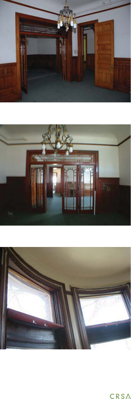
Folding wood and glass doors separate the library and dining
rooms on the main level
The grand staircase was enclosed for re code reasons when
the mansion was a group home
Wood paneled wainscot of the grand staircase

32
through single and double doorways. It also led to the
main grand staircase up to the second level. The rear
hallway (106) provided access to the secondary areas
and the rear staircase to the second level as well as
access to the basement stairs. A decorative skylight
above this staircase supplied natural light to the core of
the house. Circulation existed between the library and
dining room when folding pocket doors were opened.
A door o the northwest corner of the parlor originally
led to the exterior of the house. A door o the north
side of the dining room provided access to and from
the secondary/kitchen areas in the rear of the house. A
doorway at the rear of the foyer led to the rear hallway
where the bathroom, kitchen, basement, and rear
staircase could be accessed. A door o the east end of
the hallway was the side entrance from the east porch.
A door o the west wall of the kitchen provided circula-
tion to the small west porch.
On the second level a hallway around the grand stair-
case (200) provides access to each bedroom as well as
the original bathroom (210) and the rear staircase that
leads up to the third oor. A pocket door separated this
hallway from a small rear hallway, which provides ac-
cess to the sta ’s quarters and the rear staircase down
to the secondary areas on the main level.
A rear service staircase o the rear hallway (209) pro-
vides access from the rst oor to the second and third
oors. Access from the rst to second oor is gained
from the north (sta ) side of the pocket door while the
third oor can be reached from the south (family) side
of the pocket door. Both sets of stairs were originally
nished with oak, as typical through most of the home.
2. Existing Conditions
All of the original circulation is extant on the main
level of the building. Additional circulation was added
between the kitchen and parlor when the west porch
was expanded and enclosed. The east entrance is now
accessed through a vestibule that is part of the for-
mer east porch. The grand staircase was enclosed as a
The rear staircase leading down to the main level from the
domestic sta area of the second level
View down the main staircase from the second level

33
Fisher Mansion HSR, February 2010
a template for the new handrail. Wood treads on both
staircases will need to be cleaned and repaired. Clean
and repair all other woodwork.
Restoration Recommendations:
Completely remove the walls that enclose the grand
staircase. Replace with a historically appropriate hand-
rail that meets current code requirements for height.
Some of the balusters from the original handrail are
being stored in the carriage house and can be used as
a template for the new handrail. The walls and door
frames enclosing the rear staircase should also be
removed. Wood treads on both staircases will need to
be cleaned, repaired, sanded, and nished. Clean and
repair all other woodwork. Remove emergency re exit
and stair system. Patch exit door access with appropri-
ate brick.
C. FLOOR FINISHES
1. Historical Data/Description
Based on investigative demolition, the conjectural base
ooring layers include a diagonal 1” x 8” oak sub oor-
ing and an additional sub oor consisting of 1” x 4”
r planks throughout the house, with the exception
of the main level bathroom and entrance vestibule,
speculated to consist of only the 1”x 8” oak sub oor.
The sub oor layers are supported by 2” x 12” oor joists
on the main and second levels and by 2” x 8” oor joists
on the third level. The original nish ooring on the
main and second levels is 3/8 X 2 ¼ oak veneer, with
the exception of the main level bathroom and entrance
vestibule, which were nished ceramic tiles in decora-
tive patterns. The third oor is presumed to have not
had a nish oor on top of the r sub oor. The base-
ment ooring is an un nished concrete slab.
2. Existing Conditions
The majority of the ooring throughout the house has
undergone a variety of alterations from the original
method for meeting re code requirements during the
building’s use as a men’s group home. The rear stair-
case has also had some enclosures for re code as well
separating the third oor space from the stairwell. Stair
treads and other wood trim has maintained its original
use and character but is scratched and scu ed. One
banister on the rear staircase has been removed but is
lying on the oor in the small gap between the stairs
and the wall. An alarmed emergency re exit and stair
system now exists from Room 301.
3. Recommendations
Preservation Recommendations:
Completely remove the walls that enclose the grand
staircase. Replace with a historically appropriate hand-
rail that meets current code requirements for height.
Some of the balusters from the original handrail are
being stored in the carriage house and can be used as
The sink xture and tile oor of the main level bathroom are
presumed to be original to the house

34
nishes. On the main level the most signi cant ooring
alteration is in the parlor, where ½” quarry tile is set in
a mortar bed atop a masonite board backing. Investi-
gated demolition indicated that these layers are atop
the original oor nishes, including the oak veneer.
The other formal areas on the main level, foyer, library,
and dining room, were covered with linoleum atop a
¼” masonite board. An additional layer of carpet also
existed on top of the linoleum. In these three rooms,
the additional layers have since been removed by the
city’s property management team. The original tile is
extant in both the entrance vestibule and the main
level bathroom. On the second level, the original wood
oak ooring is extant in the bedrooms. A layer of car-
pet was installed on top of the wood ooring in Room
202, but was removed at the same time as the carpet
on the main oor. The wood is in fair condition with
scratches and scu s throughout.
The second oor restroom has a raised oor and is
covered in linoleum. The original purpose of this space
is likely as a family bathroom in the south end of the
space and a sitting room and/or servant restroom ac-
cessed via the servant’s room on the north end where
the showers are located. The original nish ooring
may still exist beneath the raised oor, but this has not
yet been determined. It is likely that the family bath-
room portion of this room was nished in a tile similar
to the main level bathroom. The rear portion of the
room would likely have been the same oak ooring
that exists in the other rooms or tile, depending on its
use.
On the third oor, the small hallway (300) wood oor is
currently covered with carpet. Room 301 is also carpet
over a 1/2” linoleum tile and ¼” masonite overlay. The
original wood ooring is under this.
The addition (303) is currently covered in carpet. The
conjectural ooring layers based on investigative de-
molition include a diagonal 1” x 8” oak sub ooring over
2” x 8” oor joists. An additional sub oor was installed
consisting of 1” x 4” r planks. Evidence shows further
alterations to include a ¼” masonite overlay, a 1/2”
View of the south central bedroom, which may have served
as a boudoir or ladies drawing room
Floor treatment in a bedroom closet
35
Fisher Mansion HSR, February 2010
linoleum tile and nally the current ooring consisting
of carpet pad and sheet carpet.
3. Recommendations
Preservation Recommendation:
Remove carpet and linoleum as appropriate to reveal
original oor treatment. Clean and repair all wood
oors. Consider removing restroom oor (210-11),
depending on intended use, to reveal original oor
treatment.
Restoration Recommendation:
Remove carpet in room 202. Clean, repair, sand, and
nish all oors. Due to the oak veneer ooring thick-
ness, there is very little wood available for sanding
and re nishing. Evaluate the feasibility of sanding the
oors. It may need to be replaced.
Remove recent layers of linoleum/vinyl material in the
closets and clean, repair, sand and nish original wood
ooring. Remove restroom oor to reveal original oor
treatment. Regardless of future use, ooring should
be replaced with materials more in keeping with the
character of the rest of the second oor.
D. INTERIOR PARTITIONS AND WALL FINISHES
1. Historical Data/Description
On the basement level the interior wall partitions con-
sist mainly of the stone foundation walls or exposed
brick walls. These walls were not generally nished
with a plaster covering, although some walls have been
painted and this may have been the historical nish.
On the upper levels the interior wall partitions are
approximately six inches thick and composed of 2 X 4
framing covered with lath and plaster. The wall n-
ishes in the vestibule, foyer, library, and dining rooms
consist of a wood wainscoting of decorative panels
with embossed wallpaper over a smooth skim coat of
plaster above. The parlor may have originally had the
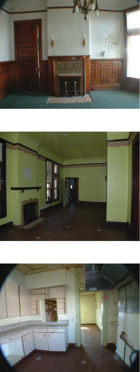
The dining room, looking north to the replace and doorway
to the kitchen area
View of the parlor, looking to the north. The coved ceiling is
an original feature of the main oor rooms
View of the original kitchen area, which was remodeled to
accommodate more intense group uses of the home

36
same wainscoting and embossed wallpaper combina-
tion or a di erent wall nish. The north hall (106) and
passageway/under-stair area (111) wall nishes are the
same combination of wood wainscoting and embossed
paper, but the wainscoting is a more simple design
of three-inch wood planks. The main level bathroom
(110) was a painted plaster. The original kitchen is also
presumed to have originally been painted plaster.
On the second level the wall nishes were comprised
of a smooth skim coat of plaster and a light paper.
Historically this may have been decorative wallpaper or
merely provided a smoother surface on which to paint.
There remains a portion of embossed wallpaper in the
hallway near the rear service stair, which has since been
painted over. The embossed wallpaper may have been
the original nish for portions of the second level.
The wall nishes of the hallway (300) in the attic level
are painted lath and plaster. The wall treatment in the
large attic room (301) is exposed brick, suggesting that
this room served simply as a utilitarian space. The origi-
nal mechanical room containing the cistern (302) did
not have nished walls and the wood studs remained
exposed. The original plaster in the stair and hallway
area is still intact and in good condition. The brick in
Room 301 is in good condition as well. The north room,
a later addition to this level, likely retains its original
wall nishes, which are stained beadboard planking
over wood stud framing.
2. Existing Conditions
The original plaster is still intact and in good condition.
The walls are currently painted. The original wood trim
still exists and is in fair condition with some scratches.
The baseboards are in fair condition as well but do
have areas that are heavily scu ed. Areas of concern
are room 208 and the baseboard of the cubby area in
room 205 where there appears to be water damage.
Closets have a variety of wall treatments. Some have
wallpaper and others are painted. The original treat-
ment is unknown.The staircase is partilly enclosed with
2 X 4’s and drywall. Original banisters and railing have
been removed.
3. Recommendations
Preservation Recommendation:
Patch and repair cracks, holes and inconsistencies in
the plaster where they may exist. Remove damaged
wallpaper in closets to the next stable layer. Clean and
repair damaged wood trim areas. Remove more recent
wall additions around the grand staircase.
Restoration Recommendation:
Further exploration can be done to more fully under-
stand original wall treatments. Patch and repair cracks,
holes and inconsistencies in plaster where they may
exist. Remove paint from wood trim in closets where
this occurs. Remove damaged wallpaper in closets.
Clean, repair, sand, and nish damaged wood trim.
Replace missing wood trim areas with the same type
of wood, design, and nish. Remove more recent wall
additions around the grand and rear staircases. For
the third oor, clean brick, secure loose and replace
missing bricks. Remove emergency exit door and stair
system and replace with brick.
E. CEILING FINISHES
1. Historical Data/Description
The ceiling nish in the majority of the basement is a
painted lath and plaster. The presence of the nished
treatment rather than exposed joists indicates that
it was an actively used area of the mansion, likely for
support space and living quarters for domestic sta .
The ceiling of Room 001, located under the original
east porch, is beadboard planking. The ceiling of the
un nished crawl space (004) is exposed wood joists.
The treatment of the ceilings on the main and second
levels appears to be similar to the walls. There is a
smooth skim coat of plaster upon which a light paper
has been placed. Original nishes may have been the

37
Fisher Mansion HSR, February 2010
paper or a painted nish. The attic level has a painted
lath and plaster ceiling in the hallway. The main room
is surmised to have had exposed rafters originally, as
well as the wire glass skylight in a metal frame that
is in plane with the slope of the roof. The mechanical
room (302) ceiling was exposed rafters. The ceiling of
the later addition (303) is the same stained beadboard
planking that is the wall nish.
2. Existing Conditions
Ceilings appear to be the original lath and plaster and
are currently painted. The original treatment is un-
known. There is a large area in the east bedroom that
has been patched. Light xtures are of various styles
but mostly modern in appearance. The light xture in
207 may be original and re ects the character of the
house. A re suppression system exists throughout
the main and second oors and is suspended just
below the ceiling. Currently, the ceiling in Room 301
is gypsum panels to re rate the roof assembly on the
underside of the roof joists. The skylight appears to be
water tight although there is ample evidence of past
disrepair.
3. Recommendations
Preservation Recommendation:
Patch and repair cracks and holes where they may ex-
ist. Repair cracks and leaks in skylight and clean glass.
Restoration Recommendation:
Patch and repair cracks, holes and inconsistencies
where they may exist. Replace light xtures with
xtures more compatible to the character of the home.
The light xture in 207 may be original and re ects the
character of the house. It could be used as an example
for the appearance of the other light xtures. Recess
the re suppression system into the ceiling. Remove
the gypsum panels in Room 301 to expose the original
ceiling. Repair cracks and leaks in skylight and clean
A re sprinkling system was installed in the 1990’s while the
mansion was a group home
The decorative skylight above the main staircase had been
covered over but remains mostly intact
Curved, decorative leaded glass was used in the transoms of
all the bay windows; it only remains in the southeast bay
38
glass. Patch possible cracks and leaks in Room 302.
F. DOORS AND WINDOWS
1. Historical Data/Description
Interior Doors:
The majority of the original interior doors were stile
and rail wood panel doors with decorative hardware.
On the main level, a set of double stile and rail wood
doors with glass panels separate the entrance vesti-
bule from the foyer and another set leads from the
foyer into the north end of the parlor. A double set of
stile and rail bi-fold doors with glass panels separates
the library and dining room. A glass panel transom
is above the sets of double doors. None of the other
interior doors on the main level have transoms above.
The hardware for the doors leading into the parlor are
more elaborate on the parlor side than the remain-
der of the door hardware on this level. In general, the
hardware for the doors is more elaborate in the formal
spaces and family bedrooms than in the secondary and
domestic sta areas. On the second level each door
has an operable transom above it, including the closet
doors. These were easily opened with special hardware
on the door frame. Transoms were helpful in circulat-
ing air and keeping the home cool during hot summer
months. On the attic level a stile and rail wood panel
door would have likely been present as the door to the
main attic space (301) and the later addition (302). The
cistern room was accessed via a pair of glazed panel
doors, which ostensibly permitted the display of the
innovative plumbing system. It is unclear whether or
not this was the original location of these cabinet-style
doors.
Windows:
Unique to this home are the access windows/doors to
the balcony area (213). These windows raise vertically
high enough for a person to step through easily and
are located in both the south and east bedrooms.
View of the door style used on the main level’s single doors
View of the double bi-fold doors separating the library and
dining room
View of the southeast bay transoms on the second level; the
original curved glass has been replaced with a at glass

39
Fisher Mansion HSR, February 2010
Windows located in the curved bays had curved glass
as well (102, 104, 202 and 206). Transoms above were a
xed leaded art glass and also curved. The bay window
in room 207 also had xed art glass in the transoms. All
other windows on this level had a xed transom with
at glass above except for rooms 209 through 212.
2. Existing Conditions
The formal areas on the main oor retain their original
doors and intact hardware. The south door into the
parlor (Room 102) has been ipped to accommodate a
change in the direction of the door’s swing. The hard-
ware and stain on the door still re ect the original ori-
entation of the door. Some of the original closet doors
remain on the second level. Other doors have been re-
placed with wood hollow core doors. The pocket door
in 209 is missing its original hardware. Most transom
hardware is still in place and in good condition. Some
transom glass has been covered for privacy.
With the exception of Room 104, all the decorative
art glass transoms have been replaced with at glass.
The curved glass in the bays remains except for the
transoms. Small shelves have been added between the
transom and window in room 206 and 207.
Overall, wood trim appears to be in good condition
with some scratches and dents. There are some areas
where small sections of the frame are missing or need
to be reattached. This is the case for the door frames for
rooms 202b and 206a.
The window on the west side of Room 301 was modi-
ed at some point to accommodate emergency egress
outside to an exterior re stair. The south windows
were replaced with aluminum frame windows. Win-
dows in the addition (303) are aluminum frame.
The door to the hall (Rm. 300) is a modern hollow metal
hinged door while the door to Room 303 is a modern
hollow wood hinged door. The decorative cabinetry
doors leading into 302 are loose.
View of the decorative skylight panel from above; some of
the panels have been damaged or are missing
Decorative wood doors accent the entrance to the cistern
room at the top of the stairs to the third level

40
3. Recommendations
Preservation Recommendation:
Clean and repair any damaged windows, frames, and
hardware. Check for weathertightness and make ap-
propriate repairs.
Clean and repair transoms. Remove coverings from the
glass.
Repair damaged wood areas. Replace missing wood
trim areas with the same type of wood and design.
Restore missing hardware that maintains the character
of the house in the area 209 pocket door.
Paint the metal door going into 301. Repair and secure
the glazed panel door cabinetry going into 302.
Restoration Recommendation:
Replace doors and hardware with originals, if they ex-
ist, or replicas after the manner of the remaining origi-
nal closet doors. Replace missing transom hardware as
well. Remove covering on transom glass above doors.
Replace existing at glass in bay transoms (102, 202,
206, and 207) with decorative art glass based on
historic photographs. Curved glass could be used in its
place if art glass is not an option. Remove the small
shelves between the transoms and the windows.
Clean, repair, sand, and nish damaged wood trim
areas. Replace missing wood trim areas with the same
type of wood, design, and nish.
Replace aluminum frame windows on the third level
with those more in keeping with the character of the
house. Clean, repair, sand, and nish damaged wood
on the glazed panel door cabinetry going into 302.
Restore hardware and secure the entire cabinet.
G. TRIM, MANTLES & FIREPLACES
1. Historical Data/Description
A wood paneled wainscot was utilized in most of the
formal spaces on the main level, the grand staircase,
A view of the curved bay in the southwest bedroom
A view of the northwest bedroom; external conduit has been
applied on top of the baseboard

41
Fisher Mansion HSR, February 2010
and second level hallway. It consisted of a repeating
pattern of panels. In the library the pattern is more
detailed, while the rest of the formal areas repeat a
vertical beveled rectangle panel. A simple wood plank
wainscot was used for the rear, secondary spaces. The
wainscot is topped with a chair rail and anchored with
a wide wood baseboard with decorative cap. The main
oor rooms also have a picture rail, located approxi-
mately one foot from the ceiling. Two replaces are ex-
tant on the main oor, in the dining room (Room 105)
and the parlor (Room 102). The two other chimneys,
located on the east wall of the library (Room 104) and
the north wall of the kitchen (Room 109) are presumed
to have been for stove pipes, rather than replaces. The
wood oor in the library does not indicate evidence
of a prior hearth, but the paneling on the east wall
in the location of the chimney appears to have been
modi ed. It is presumed that a decorative wood stove
was located on this wall with a metal panel covering
the wall behind. The wood paneling may have been
patched to match as best as possible to the rest of the
room’s wainscot. As the home was designed with a
central heating system, the replaces would have been
more decorative in nature than functional convey-
ances of heat. There is no evidence that replaces were
installed on the second or third oors.
2. Existing Conditions
The wood trim is in fair to good condition. The panel-
ing in the library (Room 104) has become quite dry and
brittle in some areas. In many of the rooms, adhesive
remains on the baseboard from a later application
of base material, such as a rubber base. Much of the
wood is moderately scu ed and has the general wear
associated with over 100 years of use. Tile around the
replaces are in good condition.
3. Recommendations
Clean, repair, sand, and nish damaged wood trim
areas. Replace missing wood trim areas with the same
CARRIAGE HOUSE
A. ORIGINAL INTERIOR AND INTERIOR COMPO
NENTS
1. Historical Data/Description
Main Level
The large carriage room was accessed by two large
double doors that swung out under the recessed entry.
Two sliding doors opened directly into the stable area
from the carriage room. A chimney to the north may
have provided venting for a small wood stove.
The stable room is lined with several windows on the
type of wood, design, and nish. Check replace sur-
rounds for any loose tile and re-grout if necessary.
Fireplaces should be inspected and may need repair if
they are intended for active use.

42
west side. A large door to the north opened for access
to the rear of the carriage house.
The small room to the south was a tack room and has
a bay that matches the house. A chimney to the west
of this room suggests a stove may have existed in this
room at one time. A narrow staircase leads up to the
second level and is located between the stable and
tack room. Another door opens from the exterior to the
bottom of the stairs.
Second Level
The loft makes up a majority of this oor on the north
end. A few large windows permit light into the space. A
door on the north side provides access to the loft from
the outside.
The south end holds two smaller living spaces that
each have their own access door from the hallway and
share a door between them. A large loft door opens
into the east room. It may have been the only way to
get furniture into this space, due to the limitations of
the narrow staircase. The west room follows the bay
footprint from the tack room below. It may have also
had a stove that connected with the chimney to the
west of the space. These rooms might have been hous-
ing for a servant at one time.
2. Existing Conditions
Main Level
The carriage room remains largely intact including
door mechanisms. The sliding doors are still in place.
The large double doors have been replaced with a
single overhead door. An extra room has been added
to the stable room. The tack room has been modi ed
from the 1968 HABS drawings. A wall now covers the
closet and restroom. The state of these covered spaces
is unknown.
Historic photo of the carriage house; access was originally on
the west side of the property
The chimney on the carriage house was topped with an
arched cap
The roof style of wide eaves and simple modillions was used
on the carriage house as well as the mansion

43
Fisher Mansion HSR, February 2010
Second Level
This level maintains its original layout. The living spaces
are in poor condition with cracked and falling plaster.
The loft structure appears to be in good condition.
3. Recommendations
As there is less architectural detail on the interior of the
carriage house, de ning elements should be preserved
and or restored. Double doors that match the original
are recommended for the main carriage house door.
Windows should be repaired and/or replaced with
like versions that are more energy e cient. The layout
of the second oor space is signi cant for its display
of the building’s structural framing; maintainig these
structural elements is recommended, even if they no
longer carry the load of the building and its roof.
B. HORIZONTAL AND VERTICAL CIRCULATION
1. Historical Data/Existing Conditions
A door provides direct access to the tack room, stable,
and stairs. A narrow staircase leads to the second oor.
A small hallway on the second oor serves the loft and
two small rooms. The stairway is in disrepair. Treads
have been broken and had patchwork repairs.
2. Recommendations
The stairway will need to be shored up with additional
support, especially if the use of the carriage house is of
a higher intensity.
C. FLOOR FINISHES
1. Historical Data/Existing Conditions
The main level oors are concrete while the second
level oors are made up of wood ooring. The condi-
tion of the wood ooring is marginal and may not be
salvagable.
The stairway in the carriage house is in poor condition, with
some broken treads
The main hayloft area of the carriage house
The southeast room on the second level of the car-
riage house ; moisture has caused plaster damage
to the walls and ceiling

44
2. Recommendations
The oor nishes will be a ected by the structural
upgrade process. If possible, salvage some of the wood
ooring or replace with like.
D. INTERIOR WALL FINISHES
1. Historical Data/Existing Conditions
Utilitarian areas have walls with exposed brick while
living areas have lath and plaster. Moisture in ltration
and lack of maintenance on the building have deterio-
rated the plaster nishes.
2. Recommendations
The exposed brick should be retained, if possible, de-
pending on the use. The walls will require re-plastering
with a compatible material.
E. CEILING FINISHES
1. Historical Data/Existing Conditions
The ceiling in the living spaces is composed of lath and
plaster. The stable and carriage room ceiling is exposed
sub oor and beams. Both have been stained the same
color and are in good condition. Some beams over the
north sliding door to the stable have been cut back.
The resulting beams have been tied to a new header.
There is signi cant damage to the second oor ceilings
in the living spaces.
2. Recommendations
The exposed sub oor and beams should be retained
as the ceiling nish, if possible, depending on use. The
ceilings will require re-plastering with a compatible
material.
SECTION SIX: LIFE SAFETY & ACCESSIBILITY

46
47
Fisher Mansion HSR, February 2010
SECTION SIX: LIFE SAFETY & ACCESSIBILITY
The following code analysis evaluates the perfor-
mance of the Albert Fisher Mansion in terms of re
safety, means of egress, general safety, and acces-
sibility.
Some of the primary Life Safety de ciencies include
an outdated building-wide re alarm system, non-
compliant egress stairs from the upper levels of the
building, and potential de ciencies in the re rating
of the interior bearing walls.
Some of the primary accessibility de ciencies are
the lack of emergency egress options from the up-
per oors, lack of an elevator to access upper oors,
problematic clear space for wheelchair access to
the majority of the rooms, non-compliant hardware
on the majority of doors, non-compliant restrooms
in the building, non-compliant or lack of adequate
signage, non-compliant reach ranges for controls,
switches, etc., and non-compliant or lack of drinking
fountains.
HISTORIC CONSIDERATIONS
The Albert Fisher Mansion serves an important
contributing role to the historic character of Salt
Lake City. Therefore, care should be taken on how
the minimum code recommendations are imple-
mented. The local building o cial retains latitude
with compliance to code in the context of historic
structures. “The provisions of this code relating to the
construction, repair, alterations, addition, restoration
and movement of structure shall not be mandatory
for historic buildings where such buildings are judged by
the building o cial to not constitute a distinct life safety
hazard.” (IBC 2006, 3407.1) By working with the building
o cial in all stages of design a solution may be reached
that increases the building’s safety while at the same time
preserving the historic character of the architecture of
the Fisher Mansion.
Some exceptions to the recommendations contained
herein can be made by the building o cial to lessen the
detrimental impact to its historic character. Major histori-
cally signi cant elements on the interior and exterior of
the building are intact and a high degree of importance
should be placed in preserving these spaces.
LIFE SAFETY ANALYSIS
Construction Type:
The Albert Fisher Mansion most likely will be categorized
as Type V-A Construction. This type is de ned as a, “Type
of construction in which the structural elements, exterior
walls and interior walls are of any materials permitted by
this code.” This construction type requires a re resistance
rating of 1 hour for the structural frame, the interior
and exterior bearing walls, the oor construction and
the roof construction and un-rated interior and exterior
non-bearing walls. (See Table 601, 2007 IBC) It appears
from oor plans and on site building analysis that the
majority of the exterior load bearing walls are composed
of un-reinforced brick masonry. There does not appear to
be combustible material in the exterior walls except for
the third level addition on the north side of the house.
Further analysis reveals that both the load bearing and

48
non-load bearing interior walls are primarily wood
framed stud walls with wood lath and plaster on both
sides. This archaic wall assembly can typically satisfy
the 1-hour re rating required by code. However, the
building code permits exemption from the 1-hour
rating if an approved re sprinkler system is installed
throughout the building. It is important to understand
that if the interior load bearing wall assemblies do not
meet the 1-hour rating and an approved re sprinkler
system is installed, then the area and height increases
described in the table below shall not apply.
Occupancy Classi cations:
The following outlines potential primary occupancies
for the Fisher Mansion. The primary occupancies are
used to determine allowable areas of the building in
conjunction with the Construction Type described
above.
PRIMARY OCCUPANCIES
(A-2) Assembly uses intended for food and/or drink
consumption including, but not limited to: Banquet
halls, Night clubs, Restaurants, Taverns and bars.
(A-3) Assembly uses intended for worship, recreation
or amusement and other assembly uses not classi ed
elsewhere in Group A including, but not limited to:
Amusement arcades, Art galleries, Bowling alleys, Plac-
es of religious, worship, Community halls, Courtrooms,
Dance halls (not including food or drink consumption),
Exhibition halls, Funeral parlors, Gymnasiums (without
spectator seating), Indoor swimming pools (without
spectator seating), Indoor tennis courts (without
spectator seating), Lecture halls, Libraries, Museums,
Waiting areas in transportation terminals, Pool and bil-
liard parlors.
(R-1) Residential occupancies containing sleeping units
where occupants are primarily transient in nature, in-

49
Fisher Mansion HSR, February 2010
cluding: Boarding houses (transient), Hotels (transient),
Motels (transient).
(R-2) Residential occupancies containing sleeping units
or more than two dwelling units where the occupants
are primarily permanent in nature, including: Apart-
ment houses, Boarding houses (not transient), Con-
vents, Dormitories, Fraternities and sororities, Hotels
(nontransient), Monasteries
Motels (nontransient), Vacation timeshare properties.
(E) Educational Group E occupancy includes, among
others, the use of a building or structure, or a portion
thereof, by six or more persons at any one time for edu-
cational purposes through the 12th grade. Religious
educational rooms and religious auditoriums, which
are accessory to places of religious worship in accor-
dance with Section 508.3.1 and have occupant loads of
less than 100, shall be classi ed as A-3 occupancies.
(B) Business Group occupancy includes, among others,
the use of a building or structure, or a portion thereof,
for o ce, professional or service-type transactions,
including storage of records and accounts.
(I-1) Institutional occupancies shall include build-
ings, structures or parts thereof housing more than
16 persons, on a 24-hour basis, who because of age,
mental disability or other reasons, live in a supervised
residential environment that provides personal care
services. The occupants are capable of responding to
an emergency situation without physical assistance
from sta . This group shall include, but not be limited
to, the following: Residential board and care facilities,
Assisted living facilities, Halfway houses, Group homes,
Congregate care facilities, Social rehabilitation facilities,
Alcohol and drug centers, Convalescent facilities.
(M) Mercantile Group M occupancy includes, among
others, buildings and structures or a portion thereof,
for the display and sale of merchandise, and involves
stocks of goods, wares or merchandise incidental to
such purposes and accessible to the public. Mercantile
occupancies shall include, but not be limited to, the
following: Department stores, Drug stores, Markets,
Motor Fuel-dispensing facilities, Retail or wholesale
stores, Sales rooms
Allowable Area & Height:
The table below summarizes the allowable area per
occupancy. It is assumed that the occupancy types
are non-separated, meaning that a re barrier exists
between each occupancy. The primary purpose of this
table is to show the actual areas in comparison with
allowable areas based on current code requirements.
Based on the information below the Education clas-
si cation would not be a compatible use for the Albert
Fisher Mansion.

50
FIRE SPRINKLERS
The existing building is currently sprinkled and the
system seems to be intact. It is unclear how compliant
the current system is. The ceilings were not lowered
to accommodate the sprinkler system, the piping is
simply suspended below the ceiling attaching to the
oor structure above. A thorough examination of the
existing system should be performed by a licensed
engineer to determine if it meets the minimum code
requirements.
ATRIUMS
An atrium is de ned as “an opening connecting two
or more stories…. Stories, as used in this de nition,
do not include balconies within assembly groups or
mezzanines….” (IBC 2006, Section 404.1) If returned to
its historic condition, the main staircase in the existing
mansion will create an atrium situation by connecting
all three stories without any separations. To meet the
intent of the code if the third level were separated from
the open stair by means of re doors and a vertical
shaft above the decorative glazed ceiling window to
Occupancy Classifi cation
Construction Type
Base Allowable Area
(S.F. per fl oor)
Area Increase due to Fire
Sprinklers (S.F. per fl oor)
Actual Height (in stories)
Allowable Height (in stories)
Height Increase (Fire Sprinklers)
Total Height Allowed (in Stories)
A-2 V-A 11,500 23,000 3 2 +1 3
A-3 V-A 11,500 23,000 3 2 +1 3
R-1 V-A 12,000 24,000 3 3 +1 4
R-2 V-A 12,000 24,000 3 3 +1 4
E V-A 18,500 37,000 3 1 +1 2
B V-A 18,000 36,000 3 3 +1 4
I-1 V-A 10,500 21,000 3 3 +1 4
M V-A 14,000 28,000 3 3 +1 4
TABLE 1 ALLOWABLE AREA AND HEIGHT
From Table 503.1, IBC 2007. Note the height and area increases are allowed if an approved automatic re sprinkler
system is installed. The increases shall not apply however if the sprinkler system is necessary to exempt out of the
interior re rated assemblies.
51
Fisher Mansion HSR, February 2010
the skylight above, the atrium would only connect two
stories and be acceptable by code.
Atriums have the architectural advantage of opening
spaces, creating volume, and enhancing way nding in
a building. The disadvantage of an atrium, especially
those not constructed per code requirements, is that
they are dangerous during res. As an example, if a
re started on the rst level the smoke would rise,
lling the corridors on the second and third levels. The
atrium as originally built could also give a re an easy
passage between levels allowing it to spread quickly
throughout the building. Because of the presence of
the sprinkler system there is a valid reason to allow the
staircase to return to its original con guration. How-
ever, if the main entry is to be left open between two
or more oors, the following additional requirements
should be met:
The atrium should to be separated from adjacent
spaces by a 1-hour re rated wall consistent with Sec-
tion 404.5.
All interior nishes in the atrium are to have a Class B
ame spread rate consistent with Section 404.7.
Smoke control system is not required per Sections
1019.1, exceptions 8. Exceptions 8 states that “…a maxi-
mum of 50 percent of egress stairways serving one ad-
jacent oor are not required to be enclosed, provided
at least two means of egress are provided from both
oors served by the unenclosed stairways. Any two
such interconnected oors shall not be open to other
oors.” (IBC 2006, Section 1020.1, exception 8)
BUILDING EGRESS, VERTICAL EXIT ENCLOSURES, AC
CESSIBLE MEANS OF EGRESS
The ability to safely and quickly exit a building in an
emergency is one of the fundamental principles in
life safety design. The term used for this is “Means of
Egress.” A means of egress as de ned in the build-
ing code as “a continuous and unobstructed path of
vertical and horizontal egress travel from any occupied
portion of a building or structure to a public way.” (IBC
2003, Section 1002)
Depending on the occupant load for the building, code
may require that each oor in the building have two
‘means of egress.’ Even though the oors have access
to exit stairs, the stairways themselves may not meet
current code requirements that would allow them to
be considered part of a ‘means of egress.’ The egress
stairs in the building should be enclosed in a minimum
1-hour re rated construction and should exit directly
to the exterior of the building or to an equally rated
space. The most problematic occupancy types would
be the assembly types where the occupant load (over
50) would trigger these requirements.
Along with general egress from the building, provi-
sions must be made for accessible means of egress.
Accessible means of egress allow for those with dis-
abilities, such as blindness, inability to walk, etc., to
also exit safely from the building. Because the building
is existing, providing an accessible mean of egress is
not required as part of the building alteration. (IBC
2006, Section 1007.1, exception 1) In some cases an
elevator can be used as an accessible means of egress,
but only if it meets certain strict criteria. In this case, if
an elevator were to be installed during the renovation,
some consideration should be given to meeting this
requirement.
FIRE SEPARATIONS
Code mandates that certain uses or functions of a
building be separated from each other by re rated
construction assemblies. A re rated assembly is an
assembly (such as a CMU wall or wood studs with gyp-
sum board) that has been tested and shown to with-
stand the presence of smoke and re for a speci ed
time. Fire rated assemblies may have ratings between
30 minutes and 4 hours. The general recommendations
should include upgrading to code mandated re rated
assemblies as required.
In the case of the Albert Fisher Mansion there are a
number of primary areas where re rated assemblies

52
should be installed as part of the remodeling process.
These are:
Between the atrium and the remainder of the •
building. (1-hour re rated assembly)
The walls and ceiling of the vertical stair en-•
closures for the stairs designated as egress stairways.
(1-hour re rated assembly) The stairs shall not func-
tion as air returns for the mechanical systems.
The shafts used for the elevator, plumbing, •
mechanical, and electrical systems that penetrate the
building’s oor system. (1 hour re rated assembly
depending on the number of oors penetrated)
Between mixed occupancy areas.•
GENERAL LIFE SAFETY
In addition to the speci c items discussed above, the
following general recommendations are noted:
Modi cation of all doors that serve an occupant load of
50 or more to swing in the direction of exit travel.
Location of exit signs to be clearly visible from the
primary corridors and show the direction and entry to
the exit doors or the egress stairways.
Seismically brace all mechanical and/or suspended
ceiling systems that will remain in the building.
Seismically brace all parapets, cornices, or large orna-
mental stone work that could pose a potential falling
hazard.
ACCESSIBILITY
The purpose of accessibility is to make the site and
building accessible to and usable by people with such
physical disabilities as “the inability to walk, di culty
walking, reliance on walking aids, blindness and
visual impairment, deafness and hearing impairment,
incoordination, reaching and manipulation disabilities,
lack of stamina, di culty interpreting and reacting to
sensory information, and extremes of physical size.”
(ANSI 117.1-98, 1)
ACCESSIBLE ACCESS AND EGRESS
All portions of the building that are public or accessible
to the public are required to be accessible. To be acces-
sible to all levels of the building, access into the build-
ing and to all public spaces in the building is required.
Areas such as janitor’s closets, mechanical rooms, and
attic and basement spaces are not required to be ac-
cessible. The primary accessibility de ciency that was
noted is the lack of an elevator. The majority of the
door hardware in the building is knob style. All door
hardware to spaces considered public is required to
be lever style. Accessibility upgrades into the building
should be evaluated. An inconspicuous ramp could be
installed to the large porch which would allow access
into the front entrance.
The access or clearance on either side of the doors is
also an issue. Doors that have both a latch and closer
are required to have 18” clear adjacent to the door
on the latch side of the door when it is being pulled,
and 12” on the latch side of the door when it is be-
ing pushed. If the door lacks the closer or the latch it
only has to comply with the pull side requirements. In
addition, depending on the approach, a clear space of
48 or 60 inches is required directly in front of the door.
The areas noted for having the most problems were
entrances into the rooms from the corridors. In some
cases, the required clear space is not possible given
the narrowness of the historic corridors.
ACCESSIBLE RESTROOMS IN PUBLIC SPACES ON MAIN
LEVEL
There is a small restroom on the main level and a larger
restroom on the second level in the historic mansion
that do not meet the current requirements for acces-
sible restrooms. The primary recommendations for the
public restrooms on the main level are as therefore as
follows:
53
Fisher Mansion HSR, February 2010
With the assumption that all restrooms will be rebuilt,
provide at least one toilet stall, and urinal (in men’s re-
stroom), for each restroom that meets the size require-
ments for accessibility (56x60 inches).
The placement of the toilet is to be 18” from the side
wall to the center of the toilet.
Grab bars are to be provided behind (36”) and on the
wall side of the toilet (42”).
The door to the accessible stall is to be self closing with
handles on both sides of the door. The latch is to be
lever style.
The supply and waste plumbing under the sinks are to
be insulated.
The mirrors are to be mounted no higher than 40”.
All accessories around the sink should be mounted
within required reach requirements.
In the men’s restroom at least one urinal should be
mounted at 17” and have a clear space of 30x48 inches.
ACCESSIBILITY IN RESIDENTIAL OCCUPANCIES
Depending on the use of the building the following
discussion focuses on accessibility for a residential
use. The current code states for R-1 occupancies that
“Where . . .dwelling or sleeping units are being altered
or added, the requirements . . . for accessible or Type
A units and . . . for accessible alarms apply.” (IBC 2006,
3409.8.7) Speci c to the R-1 occupancy, 1 accessible
unit is required per Table 1107.6.1.1, Accessible Dwell-
ing and Sleeping Units. Futhermore, “in structures with
4 or more dwelling or sleeping units intended to be
occupied as a residence, every dwelling and sleeping
unit . . . shall be a Type B unit.” (IBC 2006, 1107.6.1.2)
Further, the doorways to the individual dwelling
units should comply with the minimum clear widths
required, “Doorways shall have a clear opening of 32
inches (815 mm) minimum. Clear opening of doorways
with swinging doors shall be measured between the
face of door and stop.” (ICC/ANSI A117.1-1998, 404.2.3)
The following recommendations should be considered:
With the assumption that all restrooms will be rebuilt
as part of the individual room restorations, at least one
fully accessible unit should be provided on each of the
2nd and 3rd oors for a total of two accessible units as
de ned by ICC/ANSI A117.1-1998. (Please see Appen-
dix 2 for further speci cation on Type “A” Units)
All residential dwelling and sleeping units with the
exception of the accessible units as described above
should be Type B units as de ned by ICC/ANSI A117.1-
1998. (Please see Appendix 2 for further speci cation
on Type “B” Units)
ROOM SIGNS
None of the room signs or exit directional signs meet
accessibility requirements. All room identi cation
signs should be mounted between 48 inches to 60
inches above the oor, have raised characters contrast-
ing with the eld color of the sign, and have grade II
Braille. Rooms speci cally required to have accessible
signs are restroom, conference rooms, exit stairs, the
elevator, and doors into the di erent departments.
DRINKING FOUNTAINS
There are currently no drinking fountains installed
in the building. New drinking fountains should be
installed that meet all accessibility requirements. Since
they are in the corridors, they need to be installed so as
not to be considered an obstruction. The easiest way
to accommodate this is to recess the fountain so that a
maximum of 4” is protruding from the face of the corri-
dor wall. An alternate option is to provide a wing wall.
LIFE SAFETY RECOMMENDATIONS
The egress system of a building includes elements such
as stairs, corridors, exit signs, lighting, doors, and hard-
ware. The stairs and corridors should be upgraded to
comply with current code and meet re rating, smoke
control requirements, and collapse prevention require-

54
ments. Since the walls and ceilings for both of these
systems are existing, further study should be made to
determine what upgrades are required (if any) to make
these systems work at the desired re rating level. The
general recommendations should include upgrading
to code mandated re rated assemblies as required,
however. Any penetrations in rated wall assemblies are
to be rated assemblies (1-hour for stairs, and 20 minute
for corridors), this includes doors and jambs.
The doors along egress routes are to swing in the
direction of egress travel and are to have hardware that
allows use of the door without any special knowledge
or device.
The lighting and egress signage should be completely
upgraded. Emergency lights are to be placed to allow
for all areas of the means of egress to be illuminated at
all times that the building is occupied. A 1-footcandle
illumination level is required at the oor level along
with an emergency power system to allow operation
of the emergency lights in case of a power outage. The
egress signs are to be placed to allow visual access to
an exit from all portions of the occupied space. These
signs are to be illuminated.
Accessible egress must also be considered in this rec-
ommendation. Currently there is no oor level in the
building that meets all the requirements for accessible
egress. Each level is required a minimum of two acces-
sible means of egress. An accessible means of egress
includes access to grade, a horizontal exit, an exit stair
with an area of refuge, and an elevator with emergency
power and communication (not determined in this
study). The recommendation is, with the enclosure of
the stairs, that provisions be made to incorporate areas
of refuge on all levels in at least two of the stairwells.
From these points those with disabilities can communi-
cate with the re department and have a safe place to
wait for assistance.
The next recommendation concerns the atrium condi-
tion of the main stair. Current code would require this
stair along with the others to be enclosed so as not to
allow the free movement of smoke between building
levels. The enclosure of this stair is problematic due to
its negative impact on the historic character of the inte-
rior. The possibility of leaving the stairway open should
be of the highest priority and should comply with re
separation requirements for principal corridors and the
need to install a su cient smoke evacuation system.
Lastly, a comprehensive structural engineering analysis
with recommendations should be performed before
any substantial planning occurs.
ACCESSIBILITY RECOMMENDATIONS
The recommendations for accessibility are global and
general at this point. It is assumed that with the future
renovation some of the accessibility issues facing the
building can be easily mitigated, however, some issues
will be more problematic and may require some com-
promise to allow for building preservation.
The majority of the building cannot be considered ac-
cessible due to inadequacies such as lack of an eleva-
tor, lack of an accessible entrance, non-compliant door
hardware, clearances at doors, threshold heights, and
room and directional signage. It is recommended that
to the extent possible accessible access be made to all
primary functions of the building. Speci cally this will
include such items as:
Provide an elevator.•
Provide an accessible ramp.•
Provide necessary clearances at doors (both •
sides).
Provide access within rooms, around furnish-•
ings etc…
Replace or upgrade door hardware to allow for •
a lever style handle
Reduce height of thresholds or level changes •
where the threshold is greater than ½”.
Provide room identi cation signs for all public •
areas, exit stairs, and exit routes. The signs are to
55
Fisher Mansion HSR, February 2010
have raised characters of contrasting colors to the
background as well as Braille.
Remove or provide warning for all obstruc-•
tions along walls that protrude into accessible routes
more than 4”.
Provide drinking fountains that allow for front •
approach in a wheelchair.
Upgrade built-in reception desks to allow for •
accessible access (height and knee clearances).
These recommendations may create some issues due
to existing historic conditions. Some changes to the
building fabric to the standards imposed by the code
could be detrimental to the original architectural
character and such modi cation should be thoroughly
studied prior to recommendation.
As stated in the analysis section, there are no rest-
rooms noted in the building that meet accessibility
requirements. If the renovation includes rebuilding
the existing restrooms, all new or modi ed restrooms
in the building should be made accessible. Accessible
restrooms shall have the following features:
Access into the restroom and to lavatories, •
toilets, and urinals.
The lavatory is to have the required knee clear-•
ness and height to allow for front approach wheel
chair access.
Provide correct mounting heights to allow •
access to mirrors, soap dispensers, and paper towel
dispensers.
Provide insulation on supply and waste pipes •
under the lavatory counter.
Provide at least one accessible water closet •
with associated grab bars, and accessories mounted
at correct heights.
Provide at least one urinal (where provided) •
that is accessible.
The primary consideration with this will be the need
to plan for slightly larger restrooms to accommodate
necessary clearances at the restroom xtures.

56
SECTION SEVEN: SUSTAINABILITY & LEED CERTIFICATION

58
59
Fisher Mansion HSR, February 2010
SECTION SEVEN: SUSTAINABILITY & LEED CERTIFICATION
This section includes two components. The rst is a
supplemental report prepared by Professor Robert
A. Young for the HSR conducted by the University
of Utah students on the issues and opportunities to
be taken into consideration regarding sustainability
and energy conservation; the other is a LEED certi-
cation checklist of the potential points that could
be achieved as part of the restoration/renovation
process. These points are presumed to be achievable
in either a preservation or restoration treatment ap-
proach.
SUSTAINABILITY & ENERGY CONSERVATION
Any alteration to the exterior of the building that
a ects the exterior visual appearance will need to be
reviewed by the Salt Lake City Historic Landmarks
Commission (SLCHLC). This would primarily involve
the introduction of replacement windows, roof
mounted photovoltaic panels and solar hot water
panels, and any roof mounted HVAC equipment
systems that are visible from a public way. Likewise
any additions to the building must conform to the
SLCHLC design guidelines. Placement of panels and
mechanical equipment on the ground adjoining the
building may be possible after consultation with the
SLCHLC so long as they do not diminish the visual
appearance of the building or grounds.
TWO OVERARCHING ASPECTS
Often overlooked in many adaptive use projects are
the concepts of embodied energy and the impact
that reusing/recycling buildings and their components
can have on advancing the goals of sustainable de-
sign. In this light, the immediate urge to completely
replace a building component should be tempered
by the recognition that with each component that is
simply sent to a land ll and is not recycled, the energy
that it took create that element is permanently wasted.
Similarly, every component that is thrown away imparts
new pressures on land lls and creates the need to
extract new raw materials and use energy to fabricate
its replacement.
While not all building components can be immediately
sequestered into a recycling stream, the decision to
demolition them and replace them with a new element
should be considered carefully. When the true recogni-
tion of embodied energy and the reduction of new ex-
traction and demolition waste streams are understood,
then the true measure of how sustainable the strategies
of preservation and adaptive use will become more
apparent and subsequently a larger part of the sustain-
ability movement.
CHARACTER DEFINING PASSIVE THERMAL AND DAY
LIGHTING FEATURES
Constructed in a period before modern heating,
ventilating, and air-conditioning systems had been
introduced, the Fisher Mansion is typical of buildings
that were designed in relation to the available passive
non-mechanical systems of the era. Site orientation,
building materials, building massing, and attention to

60
solar access for passive solar heating and daylighting
were more common and better understood to be a
basic part of the thermal and luminous environmental
control systems of a building.
The Fisher Mansion is comprised of primarily brick
facades with stone foundations, sills, lintels, and other
ornamental stone features. There is a limited amount
of wood shingle-clad, stick-framed wall enclosing the
north portion of the third oor. The roof is comprised
of shingles attached to sheathing nailed to a wood
framing system. The vertical massing of this house
is typical of home of this type and originally featured
a central skylight atrium that has subsequently been
enclosed with gypsum wallboard and stick framing.
The two-story Carriage House located to the northwest
of the Fisher Mansion is similarly constructed of brick
with a shingled roof. As was common for outbuildings
of the period, there was no insulation installed during
its original construction.
The site has several fully mature deciduous trees
whose leaves provide a natural solar shade during
the summer months. During the winter months, the
bare deciduous trees admit signi cant quantities
of solar radiation which aids in passive solar gain of
the building. The site adjoins the Jordan River which
ows along the western boundary of the property and
may provide some cooling relief due to the e ects of
evaporative cooling in the area immediately adjoining
the river. There is little undergrowth in the landscaping
to interfere with bene cially cooling summer breezes
but conversely the landscaping does little to de ect
winter winds. Although the predominant winter wind
direction in Salt Lake City is from the SSE, the Carriage
House does act as a wind de ector when colder winter
winds come from the northwest.
Like other large residential buildings of this era, the
Fisher Mansion originally took advantage of porches
to provide shelter from the sun and the rain. The main
porch along the south and east elevations remains in
place while the secondary porches at the northeast
and northwest corners of the mansion have been
expanded and/or enclosed to create additional interior
space. Large windows provided opportunities for
passive solar gain in the winter and daylighting year-
round. Operable transom windows above the exte-
rior doors provided daylight and a means for passive
ventilation when the doors themselves were closed.
The vestibule at the main entrance provided an air lock
to prevent winter winds from directly entering the rst
oor hall and adjoining rooms.
On the interior, key features include a skylight stairwell
(currently enclosed), high ceilings, light colored walls,
glazing panels in doors, tall operable windows along
the exterior walls, and transom windows above doors.
The stairwell, which is conceptually an atrium that acts
as a solar chimney, was a critical component of how
the building was passively daylit and cooled. When
the stairwell was originally constructed, the open,
skylit stairwell allowed daylight to enter the central
core of the building where it could brighten otherwise
dark hallways and provide “borrowed” light through
the glazing in the adjoining doors and the transom
windows above them. The high ceilings allow summer
heat to rise away from the habitable space of the oc-
cupied rooms. The existing light colored walls (pre-
sumably concealing darker Victorian era wall paper)
enhance the re ection and penetration of the daylight
into the interior spaces. The tall operable windows
could be opened to admit fresh air when outside air
temperatures were within the comfort range or simply
to provide a comforting ow of moving air. Lastly
the transom windows, provided a dual opportunity
admitting daylight from the open stairwell skylight
as well as an opportunity for cross ventilation when
used in conjunction with the operable windows and
the three story atrium created by the skylit stairwell. In
the era of the construction of this house, prior to the
61
Fisher Mansion HSR, February 2010
invention of mechanical air conditioning systems, cross
ventilation was a primary means of providing cooling
comfort (or heat mitigation) by enhancing the passage
of air through the occupied spaces. Nighttime cooling
was achieved by leaving the lower window sash and
transom windows open thereby allowing the air to
ow through the rooms and enter the stairwell via the
transom. The natural buoyancy of the warm air causes
it to rise through the stairwell atrium and either ow
into the attic or through a skylight in the roof.
BUILDING ENVELOPE
The stone foundation and brick exterior walls provide
a thermal mass which mitigates the thermal variances
due to the solar gain and acts as a thermal storage
device. Unlike wood framed walls, masonry veneer
walls, and modern metal curtain walls, heavy masonry
walls act to more slowly absorb heat and then later
release it when air and surface temperatures begin to
fall. Although the common practice of using blown-in
insulation or expandable insulating foam products is
viable for modern twentieth century wall systems that
feature a hollow wall cavity, masonry construction of
the nineteenth century (and earlier) does not include a
cavity to receive this type of insulation upgrade. One
alternative that has been used to the severe detriment
of interior nishes and living space has been to fur out
a nominal cavity or by constructing an actual framed
partition wall on the exposed interior wall surface,
lling the cavity with insulation and enclosing the sur-
face with gypsum wallboard or a modern plaster and
lath system. The woodwork is then re t to match the
change in dimensions of the casework and trim. This
is not a viable solution for the Fisher Mansion interiors
that are enclosed by the exterior masonry walls.
Another alternative is to blow in insulation or inject
expandable insulating foams into wall and ceiling cavi-
ties. Care should be taken to identify locations where
the original knob and tube wiring could be compro-
mised by either installation process. Blown in insula-
tion comes in the form of cellulose (e.g., recycled news-
paper) or shredded cloth (e.g., denim) that has been
treated to make it insect proof and re resistant. When
using expandable foam insulation products, additional
care is needed to select a foam product that does
not introduce environmental contaminants into the
building and is formulated for use in existing buildings.
Many foam products are intended for new construc-
tion where the cavity space is lled with the expanding
foam and then the excess is trimmed away before the
interior gypsum wallboard is attached. Foams intend-
ed for existing construction do not expand as rapidly
or as signi cantly and therefore reduce the possibility
that the pressure created by the expanding foam will
damage the existing plaster and lath already secured
to the wall or ceiling. The following opportunities to
increase the thermal insulation and decrease in ltra-
tion exist at the Fisher Mansion:
Insulate wood-framed cavity walls and roof: The wood
framed roof of the Fisher Mansion and the walls of the
room at the north end of the third oor are feasible
candidates for insulation upgrades, if they have not
already been upgraded. Further inspection by remov-
ing discreet portions of the wall and ceiling by an
accredited professional will determine where these
opportunities exist.
Insulate ceiling at the foundation perimeter in base-
ment: There are a number of opportunities to inves-
tigate the feasibility of inserting insulation within
the oor cavity along the perimeter of the building.
Although the ceiling is enclosed in many of the rooms,
it may be possible to demount the ceiling or to drill
access holes in which to enable insulation to be blown
or foam injected to reduce both thermal conductance
and in ltration into the building along the top of the
foundation walls.

62
Insulate converted window openings in the basement:
There are several locations where original window
openings have been converted to use as an air intake
or discharge. The in ll surrounding these ducts should
be insulated and sealed to reduce thermal conduction
and in ltration.
Insulate/weather strip doors and other openings: Sev-
eral doors and other former window openings open di-
rectly to the outdoors or into the basement accessible
crawlspace. These doors should be weather stripped
and the openings should be lled or covered with an
airtight insulated access panel.
WINDOWS
The wood sash windows of the Fisher Mansion are a
character-de ning feature, especially the curved glass
windows and beveled art glass windows located in the
projecting bays and the tower as well as the art glass in
some interior doors. While the single pane glass is less
energy e cient than modern glazing such as double
paned low-emittance windows, a major culprit in heat
loss is through the in ltration of cold winter air (and
to a lesser extent hot air in the summer) that occurs
along the edges where the window sash and where the
window frame and the building frame come together.
There are several steps that can be taken to improve
the e ciency of the windows:
Caulking: In ltration due to lack of maintenance of
caulking around windows is a common heat loss/heat
gain problem in older houses. Verify the condition of
caulking repair/replace as needed.
Weather stripping: Similarly, the absence or failure of
weather stripping can allow in ltration to increase.
Verify the condition and as repair/replace as needed.
There are several strategies for inserting new weather
stripping into existing windows that include installing
V-shaped brass strips in the vertical spaces along the
side of the sash. Similarly, it is possible to insert Velcro
or other materials to form an in ltration barrier along
the meeting rails of the upper and lower sash.
Storm windows: While exterior storm windows can
be fabricated for the non-curved windows, the use of
interior storm windows presents a less visually intrusive
strategy that preserves the historic appearance of the
exterior. These units can be fabricated to include in-
terchangeable screen and glass inserts so that fresh air
can be admitted during temperate months of the year.
Aluminum exterior windows are not recommended
since they will detract from the historic appearance of
the building. Storm windows are not recommended
for the curved glazing or the art glass windows in the
tower and projecting bays.
Double glazing: In the at glazing, it may be possible
to replace the single pane glass with double pane
inserts by removing the single pane glazing, routing
an appropriate channel in the sash/muntin bars, and
inserting a full double pane replacement. Consultation
with a window restoration specialist can con rm the
applicability of this strategy. Full replacement (both
glass and sash) of the at glazed windows may not
be economically feasible since the cost to recover the
demolition and the replacement cost of new windows
have been shown to be less economical and less envi-
ronmentally sustainable practices. Studies have shown
that recaulking, weather stripping, and re tting the
existing windows has a signi cantly shorter payback
period that full replacement. However, should double
glazing still be desired, the replacement windows
can be simulated divided light or true divided light
windows. In a simulated divided light window, one
double-paned unit replaces all of the glazing in each
separate sash. The exterior and interior portions of the
glazing unit include false muntins as needed to repli-
cate the original appearance of the window and pro-
vide appropriate shadow lines that give the window its
63
Fisher Mansion HSR, February 2010
historic character. The windows are custom made and
the gap between the two panes of glass is concealed
by a metal insert that aligns with the location of the
muntin bars to provide the appearance of a continuous
muntin bar through the window unit. In a true divided
light window, each individual pane would be replaced
with a double paned glazing unit that matches the
pattern and size of the original window. Depending
upon the number of false muntin bars, the simulated
divided light window is typically less expensive that an
assembly of true divided light windows. Reglazing the
curved windows with double glazing will most likely
be cost prohibitive since they will require a speci c
custom made window. For further information on this
practice contact the Salt Lake City Historic Landmarks
Commission or the Utah State Historic Preservation
O ce. Any replacement windows should match the
original window opening size, the shadow pro le of
the muntin and sash, and the opening size of individ-
ual panes of the windows they replace. To install new
windows of smaller size and in lling the space around
them is not an acceptable practice under the Secretary
of the Interior Standards (Standards) which form the
basis for most reviewing agencies involved with the
oversight of historic buildings. Similarly, complete
replacement with vinyl windows with nominal shadow
lines from muntins and sash and decreased window
glazing open area is not acceptable. Lastly, replace-
ment of glazing units with one single continuous sheet
of double paned glazing that does not replicate the
muntin pro les or omits them altogether is not in con-
formance with the Standards as well.
Repair basement windows: The basement windows
should be re-glazed and the weather stripping repaired
or replaced. The broken or missing windows should
be repaired or replaced. Speci c attention should
be given to those windows and crawlspace vents in
the exposed foundation wall that lead directly for the
exterior.
Reopen the stairwell/atrium: The central atrium sky-
light that forms the stairwell has been enclosed with a
gypsum wallboard partition. The stairwell terminates
at the third oor which was originally an unheated
attic space. There is a second skylight located in the
roof directly above the skylight that caps the stairwell.
As explained above, this atrium originally acted as
a primary passive mechanism for both lighting and
ventilation. It is strongly recommended that e orts
to reopen the stairwell should be pursued as it can
provide a focal point for sustainable design e orts
within the building. Beyond simply ensuring the visual
privacy between oors, the construction of the existing
enclosing partition was possibly driven by the need
to retain heat on the lower oors in the winter. With
this factor in mind, it may still be possible to reuse the
stairwell as a daylighting and passive cooling element
by enclosing the stairwell with a re-rated glass enclo-
sure system coupled with a thermostatically or digitally
controlled louver or exhaust system located in the
attic. Coordination of this design would involve the
mechanical systems consultant, the Fire Marshall, and
the intended occupants since this atrium would need
to meet life safety requirements for re and smoke
control. A contemporary example of this can be seen at
the Big-D Construction Company Headquarters in Salt
Lake City.
HEATING, VENTILATING, AND AIRCONDITIONING
SYSTEMS
In its original construction, the Fisher Mansion was
heated with a gravity powered warm-air furnace.
There are no indications of any steam or hot-water ra-
diators within the Fisher Mansion. Each room is served
by a heating register located within the wall along the
baseboard. The gravity return register is located in an
alcove under the stairs at the rst oor. The third oor
was originally an attic space in which a mechanically
driven warm air furnace has been added. Other heat-
ing sources came from the two replaces located on
the rst oor and are currently not in use. An assess-

64
ment of the viability of reusing these replaces needs
to be completed by a building inspector to determine
their suitability for safe use.
Originally, cooling was based on the cross ventilation
and the air movement e ects generated by air mov-
ing through the interior spaces and the three-story
stairwell/atrium. Currently there are several separate
mechanical cooling systems in place at the Fisher Man-
sion. These include several evaporative coolers located
on the roof and in windows adjoining the spaces they
served. There is also one window air-conditioner serv-
ing a room that was created in the enclosed northeast
porch. An air-conditioning condenser unit is located
on the ground between the parking lot and the north
façade. Visual inspection could not reveal what system
this unit serves.
The original heating system is a centralized con gura-
tion with the furnace located in the basement. The
centralized nature of this warm air system enabled
a variety of ltration and humidi cation aspects not
found in buildings heated by steam or hot-water
radiation alone. The building was treated as one large
single thermostatic zone that was controlled by one
thermostat. What it was not designed to do was to
compensate for the stack e ect of the buoyant warm
air that it generated. Warm air rises like smoke through
a chimney stack, hence the term “stack e ect.” With the
enclosure of the stairwell, the various spaces served by
the heating system were isolated oor by oor. From
a heating perspective, this trapped warm air at the
ceiling level rather than permitting it to ow freely by
natural buoyancy up the stairwell to the oors above.
From a cooling perspective this eliminated the natural
convective cooling generated by the air ow into the
stairwell/atrium. The numerous additional mechani-
cal cooling systems point towards both a shift in what
was expected in terms of comfort and the fact that the
natural ventilation system of the original construction
no longer was deemed adequate.
The centralized nature of the original heating source
for the rst and second oors points to several poten-
tial opportunities to make the Fisher Mansion more
energy e cient and, therefore, more sustainable:
Non-residential HVAC system: The existing HVAC sys-
tem is the outgrowth of the original gravity fed warm
air furnace system found on large residential buildings
in the late-nineteenth century. Through the years vari-
ous modi cations and overlays that re ect the change
in use from a single family dwelling to a convent and
a halfway house have resulted in an agglomeration of
several di erent systems. Investigation of conversion/
replacement with a non-residentially oriented HVAC
system is in order. There appears to be su cient space
in the basement to install a small multi-zone system
that could serve all three oors individually as well
as providing for multiple thermostatic zones on each
oor. Further investigation is needed to determine if
the original ductwork, at a minimum, could be isolated
by oor and also be augmented by extending new
ductwork to serve the third oor. In this fashion, the
control of temperature, humidity, and air- ltration
could be completed from one single heating/cooling
source. This will also allow removal of the various evap-
orative coolers and window air-conditioners thereby
reducing overall maintenance expenses (e.g., number
of equipment locations, equipment obsolescence)
and improving the visual appearance of the building.
A local example of this can be found in several of the
formerly residential buildings converted to o ce space
at Fort Douglas.
Ground-coupled heat pump: Replace the existing
heating source with a ground-coupled heat pump that
can be used to seasonally provide heating or cool-
ing as needed. The piping eld needed to facilitate
the ground source heat exchange could be located
beneath the parking lot located just north of the Fisher
65
Fisher Mansion HSR, February 2010
Mansion using either a vertical con guration if geo-
logic conditions allow or in a horizontal con guration
otherwise. If a heat pump is installed, it could serve to
heat and cool the building and thus eliminate the need
for the various evaporative coolers and air-condition-
ing systems currently in place. The immediate adjacen-
cy of the Jordan River may also provide opportunities
for seasonal heat exchanges.
Digital controls: Opportunities in this regard can
ranges from simple time clock and programmable
thermostats to a fully automated central digital control
system locate onsite that can be remotely accessed
from a remote site if needed.
Enthalpy economization: The centralized air distri-
bution network also allows for a digitally controlled
monitoring system which compares the heat content
of the outdoor air and automatically switches from
mechanically cooled air to outdoor air when the
outdoor is su ciently cool to provide comfort cooling.
The addition of an appropriately sized fresh air intake
would need to be integrated into the existing system
to accommodate the air ow requirements. This option
would become more viable if a non-residential system
has been installed to replace the existing system.
Stairwell/atrium as solar chimney/stack ventilator: As
mentioned earlier, the enclosed stairwell/atrium could
be reopened to allow air and light to pass through it.
This introduces a disadvantage to the heating aspects
since (if not adequately controlled) heated air in the
winter would ow into the atrium and essentially be
wasted. However, this reintroduces the natural cool-
ing process of the original building design. In either
case, the air ow would need to be controlled in some
fashion. This can be accomplished by installing an
appropriately re-rated glass enclosure system in place
of the gypsum wallboard partition and installing a
thermostatically or digitally controlled exhaust system
at the top of the stairwell/atrium. This strategy also
opens the possibility for the use of “free cooling” in
the summer by allowing the stairwell/atrium to act as
a mechanism to relieve heats gains in the summer. In
this scenario, cooler nighttime air is introduced into
the building to ush out the accumulated heat gained
during the day and is drawn upward by either natural
convection or mechanical ventilation. The combina-
tion of the fresh outdoor air with the thermal mass of
the exterior brick walls provides the catalyst for reduc-
ing the overall mechanical cooling needed during the
daytime hours. The mechanical equipment for this in-
tegrated system could be located within the third oor
space. By extension, the air exhausted from the top of
the atrium could be used in a heat exchange system to
preheat domestic hot water.
Low pro le paddle fans on the ceiling: Due to the high
ceilings found in the Fisher Mansion, heat rises above
the occupied space year round. In the summer this is
desirable, however, in winter that heat is better used
within the occupied space. Consider installing a low
pro le paddle fan in each room. Careful attention
needs to be made to not compromise the visual integ-
rity of the space involved, especially those spaces that
have an original period chandelier. This is achievable
by selecting fans that do not project lower than the
line of sight created by existing xtures or visually in-
trude on the appearance of the chandeliers. Many fans
of this type are reversible to enhance the movement of
air upward or downward as seasonal needs warrant.
Existing HVAC equipment tuning and calibration: At a
minimum, all HVAC equipment should be tested and
tuned to optimize performance.
Ductwork cleaning: Where possible, the interior of the
ductwork should be cleaned to remove accumulated
dirt and other foreign materials.

66
Fireplaces: The existing replaces are character-de-
ning features of the spaces where they are located.
If future use is not feasible, seal the ues to eliminate
air ow and prevent wasting heat. If further use is
considered feasible, consider converting to a natural
gas fuel source and integrate venting and combustion
air intakes to a concealed location on the exterior of
the building.
Kitchen exhaust hood: The commercial kitchen fume
hood includes an industrial kitchen fan. Determine if
future use is warranted. In not remove and block open-
ing to reduce in ltration.
LIGHTING
Many of the light xtures have already been updated
with compact uorescent lamps. Continued exercise
of this strategy is encouraged, however, care must be
taken to meet the actual lighting requirements of any
new use of the interior spaces. The limited number of
xtures and their location (e.g., chandeliers and wall
sconces) indicate the need for the use of supplemental
lighting. The following considerations are advised for
the new lighting system:
Supplemental lighting: While the existing light xtures
are part of the historic character de ning features of
the interior spaces (along with the ample daylight-
ing), supplemental lighting could come in the form of
desktop and other task lighting sources. Depending
on the nal use of the building, discreet track lighting
and recessed lighting systems could be installed in the
ceiling to meet lighting needs. A local example of this
can be seen at the Chase Home Museum of Folk Art at
Liberty Park that was a noted conversion of the Chase
family house into an art gallery. Care should be used
in sensitively installing the new wiring to service any
new lighting systems. Surface mounted wiring should
be avoided.
Digital control: Many of the lights are controlled manu-
ally and consideration should be given to installing a
multi-signal occupancy sensor (e.g., a sensor that uses
two or more inputs such as motion, infrared, and ultra-
sonic energy to determine occupancy). Exterior secu-
rity lighting could be controlled by a two stage sensor
that operates the light at a lower light output until
activated by motion, infrared and ultrasonic detection
whereupon the light comes to a full output state.
UTILITIES AND SERVICE SYSTEMS
The electrical system is comprised of a number of
obsolete plug receptacles located in the baseboards.
These receptacles do not include the contemporary
third prong that is used to ground the devises be-
ing plugged into them. Further investigation will be
needed to determine if the Fisher Mansion has suf-
cient power circuits to supply adequate electricity for
the intended use and whether expansion is possible.
The plumbing systems are of late-twentieth century
manufacture and do not appear to include any of the
more modern water-conserving toilets and faucets.
Further investigation is needed into what the plumb-
ing requirements will be for any new programmatic
uses that are to be introduced. Only two xtures in
the Fisher Mansion appear to be of an appreciable age
to merit consideration as a historic character de n-
ing feature. The pedestal sink in the rst oor powder
room adjacent to the door to the basement is made of
enameled cast iron and is unique in the building. The
service sink in the basement is the other potentially
historic xture. Note: this sink is served by a drum trap
which is no longer allowed by code. In the closet at the
top of the stairs on the third oor are the remains of
some type of cistern system (i.e., metal tank with a oat
valve). Consideration for the reactivation of this cistern
may provide opportunities for rainwater capture
that can be used for irrigation of the grounds. Other
67
Fisher Mansion HSR, February 2010
sustainable measures would involve xeriscaping the
grounds and/or installing drip irrigation systems.
CONCLUDING COMMENT
The Fisher Mansion presents a number of opportuni-
ties as a demonstration of what can be accomplished
when adaptively using an existing historic landmark
for contemporary use. While the opportunities that
a ect the historic character de ning features of the
building must come under the review of the SLCHLC,
this is not typically an onerous process if the selections
of appropriately sensitive changes are considered.
The key to a successful solution is to keep the various
reviewing boards and constituencies informed along
the decision making process. As the growing number
of successfully adaptively used historic buildings grows
both locally and nationally, this building once again
provides the chance to demonstrate that preservation
is an advanced sustainability strategy.
* These considerations were compiled by Robert A.
Young, PE, Associate Professor and Historic Preserva-
tion Program Director at the University of Utah College
of Architecture + Planning as a supplement to the
historic structures report on the Fisher Mansion in Salt
Lake City prepared as a service learning project for
ARCH-6570 in partnership with the Salt Lake City His-
toric Landmarks Commission. For comments or further
information contact him at (801) 581-3909 or via email
SECTION EIGHT: STRUCTURAL & BUILDING SYSTEMS ANALYSIS
71
Fisher Mansion HSR, February 2010
SECTION EIGHT: STRUCTURAL & BUILDING SYSTEMS ANALYSIS
STRUCTURAL SYSTEM:
The Fisher Mansion’s structure remains
largely intact. It consists of an unreinforced brick
masonry superstructure, with cut, rough-faced
sandstone foundation walls, and wood frame oors.
Below grade the foundation wall consists of un-cut
eldstone with mortared joints. The roof structure
consists of wood joists. There is not a known set of
original drawings of the structure, as designed by ar-
chitect Kletting. The mansion was constructed before
the existence of building codes and seismic-resistant
engineering; the building has, however, largely stood
the test of time over its 107 year history, with only
indications of some acute settling and associated
cracking on the west side adjacent to the Jordan
River. No history of major earthquakes is known for
this area to test its seismic-resistance capacity.
Recommendations:
The structural and seismic upgrade recommenda-
tions recognize the signi cant historic value of the
existing structure and materials. Many of the recom-
mended approaches are non-invasive to the existing
historic fabric, while some require more invasive
integration. The goal of the recommendations is to
stabilize the building(s) to enhance the life and safety
of the occupants during a signi cant seismic event.
The recommendations do not suggest that the
building(s) would survive a seismic event, only that
risk factors to life and safety would be minimized.
The recommended upgrades are designed to 75% of
current code requirements for new construction.
Many of the recommendations include highly special-
ized techniques and trades. For instance, center coring
is a structural retro t which strengthens unreinforced
exterior masonry walls. This method of upgrade includes
coring a 4” to 6” diameter vertical core at the center of
the unreinforced masonry wall from the parapet or top
of wall into the foundation. Reinforcing steel bar is then
dropped into the core and lled with a polyester resin
grout. The resin grout by nature in ltrates voids in the
wall and in theory creates a monolithic reinforced wall
system. This approach doesn’t impact the exterior brick
face or the extant material nishes on the interior and is
an approach frequently used on high pro le preservation
projects.
Some approaches are more invasive but not detrimental
to extant interior nishes. Of these, strengthening oor
and roof diaphragms is the most extensive. This recom-
mendation includes installing structural wood sheathing
at each oor level and at the roof. At the roof, the exist-
ing roo ng materials will be removed and new sheathing
will be installed. At the oor levels, because much of the
ceiling nishes will be removed for electrical, mechani-
cal and re sprinkler upgrades, it may be bene cial to
consider removing all the ceiling nishes throughout
the entire mansion, installing necessary mechanical and
electrical system upgrades and then install the wood
sheathing on the underside of joists at each oor and
roof. The ceiling nishes would then be restored below
a layer of gypsum paneling. The drawback to installing
it on the underside is that anytime the ceiling joist space

72
modeling/kitchen expansion. Interior electrical panels
and breaker enclosures vary in size and capacity. The
existing electrical system will likely not allow the addi-
tion of an elevator.
Recommendations:
It is expected that all electrical systems, including the
service, distribution and wiring systems will be re-
placed if the building is rehabilitated for a new use or
fully restored. New systems and equipment will meet
modern codes and standards for health and life safety
and energy conservation.
The actual size of the new service will be design-
speci c,i.e. dependent on usage, existing and future
loads, and additional loads such as a new elevator. New
equipment such as mechanical units should be se-
lected to be compatible with the new electiracl service.
MECHANICAL SYSTEMS
Mechtech Engineering evaluated the existing condi-
tions of the mechanical system of the mansion and car-
riage house last week. An older natural gas forced air
furnace provides heat for the basement, main, and sec-
ond levels of the mansion. It is an 80% e ciency twin
set unit that does not provide air conditioning. The
air is distributed through the original heating vents,
which are located on interior walls. Modern mechanical
systems are generally located near the exterior walls
and/or windows. Two electric baseboard heaters on the
second level supplement the system. Air conditioning
on the main level is provided via two window units.
The attic level is heated by a 90% e ciency natural gas
furnace that also provides air conditioning. The duct-
work for this area is exposed. The carriage house is not
heated by a mechanical system.
The plumbing in the mansion is dated, with some pipes
being original to the system. Currently, hot water is
generated by an 80 gallon natural gas commercial hot
would require work (for electrical, sprinkler or mechani-
cal changes), the wood diaphragm would necessarily
be penetrated and therefore the structural capacity
would be diminished. The other alternative would be
to install the diaphragms on the top side of the ceiling
joists. However, this would require the removal of all
existing historic oor nishes. The existing nished
ooring is in relatively good condition, however, it is a
very thin veneer board and re nishing would be dif-
cult in the future. It may be advantageous to remove
the existing nish ooring now along with the sub-
ooring and install the new diaphragms and new oor-
ing to match existing. This also allows for future work
on the underside of the joists to take place without
disrupting the diaphragms.
Finally, the stone foundations would require a 4” to
8” thick shotcrete wall adhered to the inside of the
foundation. This has the bene t of upgrading the
foundation to current structural standards. Because
the exposed foundation is not a primary feature of
the historic mansion the recommendation to cover it
in concrete is consistent with the overall architectural
preservation goals and recommendations. The struc-
tural upgrade also calls for the removal of the unre-
inforced slab on grade. This provides a diaphragm to
mitigate the e ects of the mansion’s location in a high
liquefaction zone.
ELECTRICAL SYSTEM
Field observations have revealed that the mansion was
wired for electricity when constructed in 1893. Original
electrical wiring for the house was found embedded in
the ooring on the second level.
Various upgrades to the electrical service have been
performed over the history of the building. In many
cases this has included the addition of external conduit
to the walls and baseboard of the rooms. In 1993, the
house received an electrical upgrade as part of a re-
water heater, which is located in the basement. Histori-
cally, a cistern in the attic space collected water that was
used for the mansion’s original plumbing system. The
cistern itself is still present in a mechanical room at the
top of the stairs to the attic.
Recommendations
While the current systems could continue to serve a resi-
dential use of the building, any commercial use would
require new mechanical and plumbing systems. Active
use of the carriage house would require installation of
a mechanical system. The location of the property adja-
cent to the Jordan River makes it a good candidate for a
renewable heating and cooling approach.
SECTION NINE: COST ESTIMATE

82
83
Fisher Mansion HSR, February 2010
SECTION NINE: COST ESTIMATE
COST ESTIMATE NARRATIVE
The following cost estimates for the Albert Fisher
Mansion and associated Carriage House represent
our opinion of probable costs for renovation and res-
toration work in 2009. There are many unknown con-
ditions that must be further investigated to provide a
more detailed and accurate cost estimate. For exam-
ple, a survey of existing utilities should be completed
as well as geotechnical surveys to determine the soil
characteristics. Landscaping and site improvements
have been excluded from this estimate. In short, the
following cost estimate represents a starting point
for restoration work by providing a range for varying
levels of renovation/restoration and use categories.
The cost estimate analyses depict two options for
both the main house and the carriage house. Option
A consists of a full scale restoration of the existing
elements and Option B entails preservation and
stabilization of the existing elements. The di erences
between the two approaches are de ned below.
The preservation/stabilization approach addresses
potentially detrimental issues to the exterior enve-
lope and structure. The main objective of the pres-
ervation/stabilization approach is to arrest deteriora-
tion of the building until a speci c use and treatment
approach are identi ed. The restoration approach,
on the other hand, expands the scope of the preser-
vation/stabilization approach to include architectural
aesthetics and historically appropriate restoration.
Some speci c di erences in the cost estimate sections
between the two approaches are as follows:
1- General Demolition:
In the preservation/stabilization approach, none of the
later additions would be demolished. In the restoration
approach the removal of the additions is recommended
and included as a cost given their historical inconsistency
with the original architecture.
2- Structural:
The preservation/stabilization approach addresses issues
in the original structural system that require immedi-
ate attention for compliance with life safety and code
requirements. This includes upgrading the foundation
system through the application of a reinforced concrete
wall to the inside of the exterior stone foundation walls
and constructing a new slab on grade in the basement,
constructing new oor and roof diaphragms, bracing
chimneys, and repointing deteriorated masonry. The
restoration approach includes all of these upgrades as
well as enhancing the lateral resistance in the exterior
walls through center coring. Center coring is the struc-
tural approach that currently best allows for preservation
of existing historic nishes.
3- Exterior Envelope:
The preservation/stabilization approach addresses
necessary masonry pointing, painting and cleaning to
prevent further damage to existing building fabric. The
restoration approach addresses necessary maintenance

84
include painting existing wall surfaces where necessary
to nish o patch and repair work and re nishing the
wood ooring only to the extent of removing glues,
nails, and other residue left from additional layers of
ooring.
The restoration approach includes careful restoration
of existing wood trim and nishes, restoration and in
some cases replacement of wood ooring, wall paper
restoration, decorative skylight restoration and installa-
tion and or restoration of historic lighting xtures.
7- Mechanical:
The stabilization approach includes necessary up-
grades for occupancy, such as restroom upgrades, re
sprinkler upgrades, and ventilation system upgrades.
This does not necessarily imply replacement of exist-
ing systems. In the restoration approach, the existing
systems are to be removed and replaced with new
systems throughout.
8- Electrical:
The stabilization approach includes necessary up-
grades for occupancy. This does not necessarily imply
replacement of existing systems. In the restoration
approach, the existing systems are to be removed and
replaced with new systems throughout.
9- Conveying:
In the stabilization approach there are no improve-
ments to current conditions, which provide limited
accessibility to the various oors. In the restoration
approach, an elevator is integrated into the existing
building to provide full access to all oors.
Finally, we have included as a supplement to Option A
(Restoration) for the Main House and Carriage House
an estimate of probable additional costs by use. Dif-
fering uses require di ering approaches. For example,
an o ce use will require substantial communication
and networking options while a restaurant will require
high end commercial kitchen equipment and mechani-
cal systems. All uses may not require the full extent of
concerns as well as a more comprehensive painting ap-
proach that includes determining historically appropri-
ate color schemes and addressing the entire structure.
Brick repointing includes not only deteriorated areas,
but also the removal of inappropriate mortar and re-
placement with historically appropriate mortars. Win-
dow upgrades may include the addition of a double
pane to maximize the thermal e ciency of the existing
windows while maintaining historical appearances. In
some cases existing windows may require replacement
due to the level of damage or inappropriate window
units that replaced original fabric. The restoration
approach also includes door restoration, which will
require repair and, in some cases, replacement depend-
ing on the level of deterioration. The restoration ap-
proach also includes the reconstruction of the original
balcony railing above the porch.
4- Roo ng:
In the stabilization approach the existing roo ng is
replaced with an architectural grade asphalt shingle.
This includes the repair and replacement of all roof
accessories. In the restoration approach the roo ng is
replaced with historically appropriate cedar shingles,
and the original gutters and downspouts are refur-
bished. Additional gutters and downspouts may be
deemed necessary to maximize the e ectiveness of the
roof’s drainage system.
5- Interior Selective Demolition:
There is little interior demolition in the stabilization ap-
proach. It is mainly limited to the demolition required
for structural and envelope upgrades. There may be
some electrical and life safety demolition required to
reduce potential risks of original wiring. In the restora-
tion approach, interior demolition includes the neces-
sary demolition described above as well as removal
of select walls, nishes, plumbing, mechanical and
electrical systems in preparation for the installation of
new systems.
6- Interior Architectural Finishes:
In the stabilization approach the interior improvements
85
Fisher Mansion HSR, February 2010
structural upgrades that have been outlined. However,
to be consistent and to understand rough order costs,
all use categories include the highest recommended
structural upgrades.

