
M1 Series
Service Manual
M1G and M1M Furnaces

Typical meters used to service M1 furnaces.
A. Differential Pressure Gauge
B. Volt-Ohm Meter
C. Manometer
D. Inclined Manometer
A.
B.
C.
D.

3
TABLE OF CONTENTS
1. INTRODUCTION
Model Identification Code ........................................ 4
Serial Number Identification .................................... 4
Clearances and HUD Requirements ....................... 5
Unit specifications ................................................... 5
2. CIRCULATING AIR SUPPLY
Return air requirements .......................................... 6
Blower performance data ........................................ 6
Supply air systems .................................................. 7
3. VENTING AND COMBUSTION AIR
Roofjack selection ................................................... 7
Roofjack troubleshooting......................................... 7
Application of high wind and arctic caps.................. 8
4. ELECTRICAL WIRING
Line voltage............................................................. 8
Low voltage ............................................................. 9
5. GAS SUPPLY,CONVERSION AND LIGHTING
M1G,M1M MODELS
Gas piping ............................................................. 10
Gas conversion nat to LP ...................................... 10
Gas safety nat and LP........................................... 11
Derating for high altitude ....................................... 11
Proper pilot lighting M1G only ............................... 12
Leak checking gas line .......................................... 12
6. ACCESSORIES
Relay boxes .......................................................... 13
Cooling blowers..................................................... 13
Furnace accessories for package unit add on ....... 13
Fan timer kit .......................................................... 13
All Weather Cap ................................................... 13
7. SEQUENCE OF OPERATION , COMPONENT PARTS
AND TROUBLESHOOTING, M1G
STANDING PILOT MODEL M1G
Troubleshooting flow chart M1G-056-070 ............. 15
Troubleshooting flow chart M1G-077-090 ............. 16
Sequence of operation heating.............................. 17
TROUBLESHOOTING
Power supply ........................................................ 17
Transformer .......................................................... 17
On-off switch and fan switch ................................. 17
Low voltage wiring................................................. 18
Limit controls ......................................................... 18
Combustion air relay, 077 and 90 only .................. 18
Combustion air blower, 077 and 90 only ............... 18
Pressure switch, 077 and 90 only ......................... 18
Burner assembly ................................................... 19
Gas valve .............................................................. 20
Pilot assembly, Thermocouple, and Venturi .......... 20
Fan switch............................................................. 21
Blower assembly ................................................... 21
Heat exchanger..................................................... 22
Pilot outage ........................................................... 22
Pilot Outage Chart................................................. 23
WIRING DIAGRAMS
M1G, Natural Draft, AC adaptable........................ 24
M1G, Natural Draft, AC ready .............................. 24
M1G, Forced Draft, AC adaptable ........................ 25
M1G, Forced Draft, AC ready............................... 25
8. HOT SURFACE IGNITION SYSTEM MODEL M1M
Troubleshooting flow chart .................................... 27
Sequence of operation heating.............................. 28
TROUBLESHOOTING
Power supply ........................................................ 28
Transformer .......................................................... 28
Low voltage wiring................................................. 29
Limit controls ......................................................... 29
Intergrated control board ....................................... 29
Combustion air blower .......................................... 31
Pressure switch..................................................... 32
Hot surface ignitor ................................................. 33
Burner assembly ................................................... 33
Gas valve .............................................................. 33
Blower assembly ................................................... 34
Heat exchanger..................................................... 34
WIRING DIAGRAM
M1M, All ................................................................ 35
4
Model Identification
Door Color
W = White
G = Gray
Cabinet Size
A = 20" x 24" x 56”
B = w/Coil Cavity, 20” x 24” x 76”
Electrical Code
A = 1PH, 60 Hz, 120 VAC
Heating Capacity
Input, BTUH (000)
Application
M = Manufactured Home
Furnace Series
Fuel, Type of Combustion
G = Gas, Direct Vent, Pilot Burner
Natural or Forced Draft
M = Gas, HSI, Forced Draft
B = Gas, Gun Burner
S = Oil, Gun Burner
M 1 G H - 056 A - BW
Comfort Model
H = Heating
A = Heating, A/C Ready
B = A/C Ready, 3 Ton
C = A/C Ready, 4 Ton
D = A/C Ready, 5 Ton
INTRODUCTION
This service manual is designed to be used in conjunction with
the installation manual provided with each furnace.
The downflow sealed combustion furnaces illustrated in this
service manual represent the very latest in high efficiency gas
furnace technology. Certain controls within the furnace
consist of highly sophisticated electronic components which
are not user serviceable. It is essential that only competent,
qualified, service personnel attempt to install, service, or
maintain this product.
This Service manual was written to assist the professional
HVAC service technician to quickly and accurately diagnose
and repair most malfunctions of this product.
This service manual covers standing pilot and hot surface
ignition gas burner models. The overall operation of both of
these models is essentially the same, with the exception of
certain controls which may be unique to each model.
This manual will deal with all subjects in a general nature (i.e.
all text will pertain to all models) unless that subject is unique
to a particular model or family, in which case it will be so
indicated.
It will be necessary for you to accurately identify the unit you
are servicing, so you may be certain of approved diagnosis
and repair. (See Unit Identification, Below)
This manual was prepared by the senior Technical Service
Department and the Communications Department.
The information contained in this manual is intended for use
by a qualified service technician who is familiar with the safety
procedures required in installation and repair and who is
equipped with the proper tools and testing instruments.
Installations and repairs made by unqualified persons can
result in hazards subjecting the unqualified person making
such repairs to the risk of injury or electrical shock which can
be serious or even fatal not only to them, but also to persons
being served by the equipment.
If you install or perform service on equipment, you must
assume responsibility for any bodily injury or property dam-
age which may result to you or others. We will not be
responsible for any injury or property damage arising from
improper installation, service, and/or service procedures.
WARNING:
!
Serial No. Identification
Model Series
M 1 G 9807 - 05432
Production
Year/Month
Production Code

5
Table 1. M1 Furnace Specifications
NOTICE TO INSTALLER
Installer is advised to follow carefully all instructions and
warnings in this manual to insure maximum performance,
safety, and operating efficiency of these appliances. Improper
installation may create hazardous conditions, and will void the
appliance warranty.
1. SPECIFICATIONS
GENERAL DESCRIPTION
M1 Series gas and oil furnaces are listed direct vent (sealed
combustion), downflow heating appliances for manufactured
(mobile) homes, recreational vehicles, and for use in residen-
tial/modular/commercial construction. The furnace must be
located so that venting can be properly achieved.
“A” cabinet models may be installed with Optional Coil Cabi-
net Model #911969 for air conditioning.
“B” cabinet models are factory equipped with a built-in coil cavity.
Multi-speed blower assemblies (See Accessories) have been
certified for field installation in M1 Series furnaces. An air
conditioner can be easily field installed with M1GH Series
furnaces if used in conjunction with certified 2-wire relay box,
p/n 903092A or 4/5 wire relay box 902898A.
INSTALLATION STANDARDS
Installer shall be familiar with and comply with all codes and
regulations applicable to the installation of these heating
appliances and related equipment. In lieu of local codes, the
installation shall be in accordance with the current provisions
of one or more of the following standards.
Electrical Supply - 120 Volts, 60 Hz, 1 Ph. Thermostat Circuit - 24 Volts, 60Hz, 30 VAC
Fuse or Breaker - 15 Amps. Norm. Anticipator Setting - 0.4
Temperature Rise - 45° to 75°F Manifold Pressure - Natural Gas - 3.5” w.c. LP Gas - 10” w.c.
High Altitude - See Table 7. *Nominal blower capacity only – relay must be field added.
For Canadian High Altitude (2,000'-4,500'),reduce the gas manifold pressure to 3.0" w.c. for natural gas and to 8" w.c. for LP gas.
Furnace Input Output Orifice No E.S.P. Pilot Ignitor Comb. Motor A/C Ready
Model No MBtu/h MBtu/h Nat. LP In WC Burner Direct Blower Hp Tons
M1GH 056 56 45 29 45 0.2 x 1/8 2*
M1GB 056 56 45 29 45 0.3 x 1/3 3
M1GC 056 56 45 29 45 0.3 x 1/2 4
M1GD 056 56 45 29 45 0.3 x 3/4 5
M1GH 070 70 57 24 42 0.3 x 1/5 2½*
M1GB 070 70 57 24 42 0.3 x 1/3 3
M1GC 070 70 57 24 42 0.3 x 1/2 4
M1GD 070 70 57 24 42 0.3 x 3/4 5
M1GH 077 77 60 21 40 0.3 x x 1/4 3*
M1GB 077 77 60 21 40 0.3 x x 1/4 3
M1GC 077 77 60 21 40 0.3 x x 1/2 4
M1GD 077 77 60 21 40 0.3 x x 3/4 5
M1GH 090 90 70 17 36 0.3 x x 1/4 3*
M1GB 090 90 70 17 36 0.3 x x 1/4 3
M1GC 090 90 70 17 36 0.3 x x 1/2 4
M1GD 090 90 70 17 36 0.3 x x 3/4 5
M1MA 056 56 46 29 45 0.2 x x 1/8 2
M1MB 056 56 46 29 45 0.3 x x 1/3 3
M1MC 056 56 46 29 45 0.3 x x 1/2 4
M1MD 056 56 46 29 45 0.3 x x 3/4 5
M1MA 070 70 57 24 42 0.3 x x 1/5 2½
M1MB 070 70 57 24 42 0.3 x x 1/3 3
M1MC 070 70 57 24 42 0.3 x x 1/2 4
M1MD 070 70 57 24 42 0.3 x x 3/4 5
M1MB 077 77 62 21 40 0.3 x x 1/4 3
M1MC 077 77 62 21 40 0.3 x x 1/2 4
M1MD 077 77 62 21 40 0.3 x x 3/4 5
M1MB 090 90 72 17 36 0.3 x x 1/4 3
M1MC 090 90 72 17 36 0.3 x x 1/2 4
M1MD 090 90 72 17 36 0.3 x x 3/4 5

6
a. Federal Manufactured Home Constructions & Safety
Standard (H.U.D. Title 24, Part 3280.707[a][2])
b. American National Standard (ANSI-119.2/NFPA-501C)
for all recreational vehicle installations.
c. American National Standard (ANSI-Z223.1/NFPA-54)
and/or CAN/CGA B149 for all gas-fired furnace models.
d. American National Standard (ANSI-Z95.1/NFPA-31) and/
or CSA B139 for all oil-fired furnace models.
e. American National Standard (ANSI-C1/NFPA-70) and/or
CSA 22.1 Canadian Electric Code Part 1 for all electrical
field wiring.
f. Units have been investigated under standards UL 307A
& B, ANZI 21.47a — CAN/2.3a - 1995, and CSA B140.10.
2. CIRCULATING AIR SUPPLY
RETURN AIR PROVISIONS
U.S.A. home manufacturers shall comply with all of the
following conditions to have acceptable return air systems for
closet installed forced air heating appliances:
a. Regardless of the location, the return air opening into the
closet shall not be less than specified in the appliance’s
listing.
b. Means shall be provided to prevent inadvertent closure
by a flat object placed over the return air opening when it
is located in the floor of the closet (versus the vertical front
or side wall).
c. The cross-sectional area of the return duct system lead-
ing into the closet, when located in the floor or ceiling shall
not be less than 235 square inches (or 390 square inches
for 5 ton ready M1 Furnaces).
d. The total free area of openings in the floor or ceiling
registers serving the return air duct system must be at
least 352 sq. in. At least one register should be located
where it is not likely to be covered by carpeting, boxes and
other objects.
e. Materials located in the return duct system must have a
flame spread classification of 200 or less. This includes a
closet door if the furnace is in a closet.
f. Noncombustible pans having 1" upturned flanges are
located beneath openings in a floor duct system.
Table 2. Blower Performance Data
ESP
(In. W.C.)
Low Med-Lo Med-Hi High Low Med-Lo Med-Hi High
1/8 HP 1 024 0.1 820 730
9 X 7.5 0.2 790 680
0.3 720 610
056 - H, A 0.4 650 550
UNITS 0.5 560 450
0.6 430 330
1/5 HP 1 030 0.1 950 850
9 X 7.5 0.2 910 810
066-A 0.3 850 730
070 - H,A 0.4 780 670
UNITS 0.5 680 580
0.6 570 480
1/4 HP 1 036 0.1 1210 1140
10 x 8 0.2 1190 1110
077 - H, B 0.3 1140 1050
090 - H, B 0.4 1090 990
086-B 0.5 1030 930
UNITS 0.6 970 870
1/3 HP 2 036 0.1 1020 1350 960 1210
10 x 8 0.2 1000 1330 940 1170
056 - B 0.3 970 1260 890 1110
070 - B 0.4 940 1210 850 1050
UNITS 0.5 890 1130 790 980
0.6 840 1060 730 900
1/2 HP 4 047 0.1 890 1070 1270 1480 880 1050 1220 1340
11 X 8 0.2 880 1060 1260 1460 870 1040 1210 1330
0.3 860 1020 1220 1400 850 1000 1160 1270
C UNITS 0.4 840 1000 1180 1350 820 980 1110 1210
0.5 810 960 1120 1280 800 940 1070 1160
0.6 760 920 1080 1220 750 890 1010 1090
3/4 HP 4 054
10 x 8 0.2 900 1110 1450 1850 870 1070 1420 1700
4 POLE 0.3 860 1080 1410 1810 840 1050 1380 1650
0.4 830 1040 1370 1760 820 1030 1350 1630
D UNITS 0.5 790 1020 1340 1730 780 1010 1320 1590
0.6 770 990 1320 1700 760 980 1290 1550
HP, Wheel,
Poles, Units
Coil
Size
WITHOUT COIL WITH COIL
Speed

7
g. Wiring materials located in the return duct system shall
conform to Articles 300-22 of the National Electrical
Code (ANSI C1/NFPA-70).
h. Gas piping is not run in or through the return duct system.
i. Test the negative pressure in the closet with the air-
circulating fan operating at high speed and the closet
closed. The negative pressure is to be no more negative
than minus 0.05 inch water column.
j. For floor return systems, the manufactured home manu-
facturer shall affix a prominent marking on or near the
appliance where it can be easily read when the closet
door is open. The marking shall read:
k. Air conditioning systems may require more duct, register
and open louver area to obtain necessary airflow. Use
NORDYNE’s certiduct program to determine proper
duct size for A/C.
Air Distribution Systems
For proper air distribution, the supply duct system must be
designed so that the static pressure measured external to the
furnace does not exceed the listed static pressure rating
shown on the furnace rating plate.
Before installing an air conditioner system, consult home
manufacturer for duct system maximum capacity. Location,
size, and number of registers should be selected on the basis
of best air distribution and floor plan of the home.
Table 3. Roof Jack Assemblies
CAUTION:
HAZARD OF ASPHYXIATION: Do not cover or
restrict return air opening.
!
3. VENTING AND COMBUSTION AIR
ROOF JACK SELECTION
Note: Install only Roof Jack Assemblies listed in Table 3 on
this heating appliance.
a. Determine depth of ceiling cavity from center of roof
opening to center of ceiling opening. (See Dimension “A”
in Figure 1).
b. Determine ceiling height and subtract height of furnace.
(See Dimension “B” in Figure 1).
c. Add dimensions A + B (and X from Table 3 and Figure 2
if slant deck flashing is used). The total length of (A + B +
X) must be within the minimum and maximum range of
one of the Roof Jacks listed in Table 3.
ROOF JACK TROUBLE SHOOTING
The roof jack assembly is a telescoping type assembly (see
selection) that is made up of a pipe within a pipe construction.
The inner pipe (5”) is for the flue gases to exit the home. The
outer pipe (8”) is using the space in-between the 5” and 8” pipe
for combustion air. If the furnace is smothering itself out, after
a short time, on natural draft models, or pressure switch does
not make contact on M1M model, slide up air inlet a few inches
and check for debris in pipe. Clean out and check complete
flue assembly for blockage. On new homes make sure no
building materials fell in the top (air inlet or exhaust). Also
remove top and make sure no seams have opened up on roof-
jack assembly. On the M1G furnace (natural draft model) the
air inlet limit tripping is caused from a unbalanced draft, which
means the air inlet becomes a better flue than the flue itself.
Check-out Procedure:
Is furnace filter clean?
If furnace is installed in closet, what is the louver open area?
The installation instructions state the minimum open area
required is 235 sq. in., or 390 sq. in. for 5 ton.
Inspect roof-jack for internal blockage.
Inspect inside of upper combustion air box for debris.
With burner removed, reach inside lower air box into com-
bustion air chute to check for debris (insulation, roofing
material, drywall, etc.) and look in the bottom of the heat
exchanger for debris.
SSAW
T
27
47 - 2
AW= ALL WEATHER
FLASHING
PITCH/12" RISE
0=FLAT
2=2.5/12
4=4/12
MIN. ADJ.
LENGTH
F=
S=
FLAT FLASHING
SLANT FLASHING
TYPE:
BLANK=NON-TRANSIT
T= TRANSIT MODE
MAX. ADJ.
LENGTH
FLUE STEEL TYPE
A= ALUMINIZED
S=STAINLESS
Approx. Length
Model Number Below Flashing
(F,S)AW(T)1523-(0,2,4)(A,S) 15" - 23"
(F,S)AW(T)2135-(0,2,4)(A,S) 21" - 35"
(F,S)AW(T)2747-(0,2,4)(A,S) 27" - 47"
(F,S)AW(T)3563-(0,2,4)(A,S) 35" - 63"
(F,S)AW(T)5195-(0,2,4)(A,S) 51" - 95"

8
Is gas orifice the proper size for the gas in use?
Check manifold gas pressure at low fire (14 seconds
nominal) before it steps to normal high fire.
The compression fitting on the pilot tube must be tight.
Is the burner aligned perpendicular to the burner mounting
plate?
APPLICATION OF ALL WEATHER CAPS
In most cases, when a pilot is blown out during windy condi-
tions, an all weather cap will take care of this problem.
Extension(s) will also help (see Pilot Outage). See Accessory
Chart for part numbers.
All weather caps are used in areas of extreme cold (10° or
lower) for long periods of time. This causes ice to form and
block combustion air. Replace the standard crown with the
optional all weather cap. Follow instructions with the new all
weather cap. See Accessories section for part number.
a. If the roof jack crown is covered or blocked with snow, the
furnace will not operate properly. If the home is located in
regions where snow accumulation exceeds 7” (HUD
snowload zones) use an external roof jack extension p/n
901937.
b. M1 furnaces may be used with roof jacks as tall as 170”
(except M1M 056 models, which are limited to 120”).
Internal roof jack extensions (p/n 901935 - 10”, p/n 903107
- 18”) can be used to increase roof jack height. All connec-
tions inside the home must be made below the ceiling.
ELECTRICAL WIRING
Line Voltage Wiring (See Figure 15)
The line voltage (115 volt) to the furnace must be supplied
from a dedicated circuit containing the correct fuse or circuit
breaker for the furnace. See Table 5. An electrical switch
should be readily accessible from and within sight of the
furnace. All line voltage connections must be made within the
junction box located within the furnace.
The furnace cabinet must have an uninterrupted, unbroken
ground to minimize injury should an electrical fault condition
occur. The controls used in this furnace also require an earth
ground to cooperate properly. Acceptable methods for ground-
ing are electrical wire or conduit approved for electrical ground
service. Do not use gas piping as an electrical ground.
NOTE: Proper line voltage polarity must be maintained in
order for the control system to operate correctly. Verify
that the incoming neutral line is connected to the white
wire and the incoming "hot" line is connected to the black
wire in the furnace junction box. This furnace will not
operate unless polarity and ground are properly con-
nected. (See Figure 16).
Never use gas lines as ground.
To determine polarity, the incoming power supply should be
checked. The "Hot" lead will read 115V to ground. The
"neutral" should read 0V to ground.
Figure 2.
Figure 3.
Figure 1. Roof Jack Assemblies
Roof Jack
Flat Roof
Ceiling Cavity
Ceiling
Flue Pipe
Combustion
Air Pipe
Flashing
This joint
may be
above ceiling
"A"
"B"
56" or 76"
Furnace
5/12 ROOF SLOPE
2
SLANT DECK
/12
1
2
ROOF JACK WITH
2
FLASHING
/12 SLANT
1
2
ROOF JACK
SLANT DECK
FLASHING
PITCHED
ROOF
CEILING
CEILING CAVITY
ROOF OPENING
CEILING OPENING
"X" (SEE TABLE 1)
6

9
Supply Voltage
Supply voltage to the furnace should be nominal 115 volts. It
must be between 103 volts and 127 volts. Supply voltage to the
furnace should be checked with furnace in operation and blower
running. Voltage readings outside the specified range can be
expected to cause operating problems. Their cause MUST be
investigated and corrected.
CONNECT THERMOSTAT WIRES
a. Insert 24 volt wires through the plastic grommet just
above the control panel.
b. Connect the thermostat wires to the furnace low voltage
pigtails (see Figure 5).
c. Connect low-voltage circuit to the wall thermostat.
d. A hole may be made in the furnace cabinet to ease
thermostat wiring. Make sure that the wiring is protected
from the sharp edge of the added hole.
NOTE: The thermostat should be installed 4 to 5 feet above
the floor on an inside wall which is relatively free from direct
sources of heat or cold drafts. The nominal anticipator setting
is 0.4. (Refer to the thermostat literature for additional infor-
mation.)
Five-conductor thermostat wire is recommended for 24 volt
low-voltage circuit (2-wire is required for furnace only; 5-wire
for heating and optional cooling systems).
Once the furnace is installed check the thermostat anticipator
against the nominal setting of 0.4:
1. Connect the milliamp meter in series with the “W” circuit.
2. Energize a call for heat.
3. Read the value of the milliamps.
4. Adjust the heat anticipator of the thermostat to the value
read on the milliamp meter.
If the heat anticipator is set too high the furnace may delay in
coming on.
If the heat anticipator is set too low the furnace may cycle
frequently and not provide the desired comfort level.
Figure 6. Line Voltage Field Wiring
T’STAT
Wire Gauge
2-Wire 5-Wire
(Heating) (Heating/Cooling)
24 55 25
22 90 45
20 140 70
18 225 110
Recommended T’STAT Wire
Len
g
th
(
Unit to T’STAT
)
Table 4. Thermostat Wire Gauge
Figure 5. Control Panel (All Models)
To Combustion
Blower or
Flame Roll-Out
Switch
Thermostat Wires
Blower
Plug
On-Off
Switch
On-Auto
Switch
(Heating
Models Only)
To Gas Valve
or Burner
Power
Entry
Furnace
Control Box
Figure 4. Thermostat Wiring A/C Ready Models
Rc
R
H
W
G
Y
Red
White
Green
Yellow
Red
White
Green
Grey
**
To Cooling Unit
Thermostat
M1G A/C
Ready Furnace
Field Supplied
Disconnect Within
Sight of Furnace
Field Supplied
Panel Connector
Field Supplied
Fused Service
Panel
Black (Hot)
White (Neutral)
Green or Bare (Ground)
Black
White
Black
White
Black
White
Field Line Voltage
Wiring
Factory Line
Voltage Wiring
Ground
Ground
Ground

10
f. It is not necessary to convert the pilot orifice.
g. For Honeywell gas valves with the regulator converter
(Figure 8), check for the letters NAT or LP on the pressure
regulator cap. Unscrew the cap, invert it, replace, and
tighten until snug.
h. For the Robertshaw gas valve with the regulator con-
verter (Figure 9), remove the black cover and unscrew
the converter located on top of the gas valve. Invert the
converter. (For “LP” the red ring will be located at the
bottom and the “LP” stamping on the converter will appear
right side up.) Then screw converter back into the regu-
lator, hand tight plus 1/8 turn, and replace the black cover
onto the converter top to protect the threads.
i. Reassemble the burner assembly into the furnace.
j. Reconnect the gas piping and electrical wires to the gas
valve.
k. Open the manual shut-off valve and follow the FURNACE
START-UP procedure as outlined previously in this manual
to put the furnace into operation.
NOTE: The pilot flame is adjustable by turning the adjustment
screw located on the gas valve with a small screwdriver. (See
Figure 10)
5. GAS SUPPLY, CONVERSION, AND
LIGHTING – M1G AND M1M MODELS
GAS PIPING
Sizing and installation of fuel lines must be in accordance with
federal, state and local regulations. All piping shall be black
iron pipe, or equivalently sized steel tubing. Internally tinned
copper tubing may be used for gas supply systems.
Fuel line installations other than typical installations shown in
Figure 7 must comply with the fuel piping provisions stated in
the Federal Manufactured Home Standard (H.U.D. TITLE 24,
PART 280) and the National Fuel Gas Code (ANSI-Z223.1/
NFPA-54).
a. Optional fuel inlet lines are available for all gas furnace
models to permit the addition of a 1/2" F.P.T. shut-off
valve above the floor.
NOTE: Shut-off valve must be designed and listed for use
with liquid petroleum (LP gas).
The gas supply to your home will either be Natural Gas or LP
(bottle gas). Your furnace is factory equipped to operate on
Natural Gas. If your gas supply is LP, you must convert the
furnace. The necessary instructions for the gas conversion are
found on the lighting instruction label attached to the furnace in
Section 16, Service Guide.
For natural gas operation, the furnace is designed for 7" W.C.
inlet pressure. Pressure is reduced to 3-1/2" W.C. by the
pressure regulator in the gas valve. The maximum inlet
pressure for the valve is 13” W.C.
For L.P. gas, pressure to the gas valve must be more than 11"
W.C. but not more than 13" W.C. Pressure is reduced to 10"
W.C. by the pressure regulator in the gas valve.
GAS CONVERSION
This gas fired heating appliance was shipped from the factory
for use with natural gas. However, the appliance can be
converted for use with LP gas. Use the following procedure
for gas conversion of the burner.
ATMOSPHERIC AND DIRECT IGNITION FURNACES
a. Follow the instructions to “Turn Off Gas to the Appliance.”
b. Disconnect the gas pipe union and the electrical wires
connected to the gas valve.
c. Remove the pilot tube and thermocouple from the gas
valve (M1G* only).
d. To remove the gas valve assembly, remove screw(s)
from gas valve bracket. Gas valve and spud may be
removed. Orifice is located at the end of the spud
(M1G*,M1M*).
e. Replace the main orifice with the L.P. gas orifice supplied
in the envelope located by the gas valve. Check to insure
the orifice size matches the nameplate. NOTE: For eleva-
tions over 2,000 feet, use Table 7 to determine orifice size.
To Gas
Supply
Floor
Control
Panel
On-Off-Fan
Switch
Alt. Fuel
Line Entry
Floor Cavity
Figure 7. Typical Gas Piping
CAUTION:
The furnace must be converted by a qualified
technician. Improper conversion can cause
unsafe operation, explosion, fire and/or
asphyxiation.
!

11
LIGHTING AND FURNACE SHUTDOWN
GENERAL-ALL MODELS
Read the safety information on the front page of these
installation instructions before lighting furnace. DO NOT
ATTEMPT TO LIGHT FURNACE IF YOU SMELL GAS.
SAFETY INFORMATION
FOR YOUR SAFETY READ BEFORE LIGHTING.
a. The first lighting of the furnace after any home setup
must be performed by a qualified service technician.
b. If this appliance has a pilot that must be lit by hand, follow
these instructions exactly.
c. BEFORE LIGHTING smell all around the furnace for gas.
Be sure to smell next to the floor because some gas is
heavier than air and will settle on the floor.
d. WHAT TO DO IF YOU SMELL GAS: Do not try to light
any appliance. Do not touch any electric switch and do
not use any phone in your building. Immediately call your
gas supplier from a neighbor’s phone. Follow the gas
supplier’s instructions. If you cannot reach your gas
supplier, call the fire department.
e. Use only your hand to push in the gas control lever. Never
use tools. If the lever will not push in by hand, don’t try to
repair it. Call a qualified service technician. Force or
attempted repair may result in a fire or explosion.
f. Do not use this furnace if any part has been under water.
Immediately call a qualified service technician to inspect
the furnace and to replace any part of the gas valve or
control system which has been under water.
Reference Sources: ANSI Z233.1 & NFPA 54, National Fuel Gas Code.
For Canadian high altitude (2,000 - 4,500'), reduce gas manifold pressure to 3.0” W.C. for natural gas and 9” W.C. for LP gas.
NOTE: Do not attempt to change the size of an orifice by drilling it out. To do so will void the manufacturer’s warranty.
Table 7. High Altitude Derate
Figure 8. Convertible Pressure Regulator Cap
PRESSURE
REGULATOR
CAP
M11678
N
A
T
N
A
T
L
P
L
P
N
A
T
N
A
T
OR
OTHER SIDE
OF CAP
Honeywell
Valve
Figure 9. Convertible Pressure Regulator
Robertshaw
Valve
FURNACE ORIFICE SIZE AND ALTITUDE - FEET
MODEL OUTPUT CAPACITY SEA LEVEL 2000 3000 4000 5000 6000 7000 8000 9000 10000
ORIFICE SIZE - NAT. GAS 29 293030303031313132
M1M/G 056 ORIFICE SIZE - LP 45 46 47 47 47 48 48 49 49 50
OUTPUT- MBTUH 45.4 41.8 40.1 38.5 37.0 35.5 34.1 32.7 31.4 30.2
ORIFICE SIZE - NAT. GAS 24 252627272828292930
M1M/G 070 ORIFICE SIZE - LP 42 42 43 43 43 44 44 45 46 47
OUTPUT- MBTUH 56.7 52.3 50.2 48.2 46.2 44.4 42.6 40.9 39.3 37.7
ORIFICE SIZE - NAT. GAS 21 232324252627282829
M1M 077 ORIFICE SIZE - LP 40 41 42 42 42 43 43 44 44 45
OUTPUT- MBTUH 61.7 56.9 54.6 52.4 50.3 48.3 46.4 44.5 42.7 41.0
ORIFICE SIZE - NAT. GAS 21 232324252627282829
M1G 077 ORIFICE SIZE - LP 40 41 42 42 42 43 43 44 44 45
OUTPUT- MBTUH 59.9 55.2 53.0 50.9 48.9 46.9 45.0 43.2 41.5 39.8
ORIFICE SIZE - NAT. GAS 17 181919202122232426
M1M 090 ORIFICE SIZE - LP 36 37 38 38 39 40 41 41 42 43
OUTPUT- MBTUH 71.7 66.1 63.5 60.9 58.5 56.1 53.9 51.7 49.7 47.7
ORIFICE SIZE - NAT. GAS 17 181919202122232426
M1G 090 ORIFICE SIZE - LP 36 37 38 38 39 40 41 41 42 43
OUTPUT- MBTUH 69.7 64.2 61.7 59.2 56.8 54.6 52.4 50.3 48.3 46.3

12
LIGHTING INSTRUCTIONS FOR STANDING
PILOT MODELS
a. Stop! Read the safety information.
b. Set the thermostat to the lowest setting.
c. Turn off all electric power to the appliance.
d. Push in the gas control lever slightly and move left to
“OFF.” DO NOT FORCE.
e. Wait ten (10) minutes to clear out any gas. If you smell
gas, STOP! Follow step “d” in the SAFETY INFORMA-
TION. If you don’t smell gas, go to the next step.
f. Find pilot - follow metal tube (pilot tube) from gas control
valve. Open hinged fire observation door. The pilot is
found at the end of the pilot tube, just left of the pilot shield.
g. Slightly depress the gas control lever and move it right to
the “ON” position and release; then move it to the “PILOT”
position.
h. Move the control lever to “SET” and hold. Immediately
light the pilot with a match. If this furnace is equipped with
a Piezo Ignitor, activate spark lever/button several times
until flame is visible through observation door. Continue
to hold the control lever for about one (1) minute after the
pilot is lit. Release the lever and it will spring back to the
“PILOT” position. Pilot should remain lit. If it goes out,
repeat steps “d” through “h” above. If the lever does not
spring back when released, stop and immediately call
your service technician or gas supplier. If the pilot will not
stay lit after several tries, move the gas control lever to
“OFF” and call your service technician or gas supplier.
i. Move the gas control lever left to “ON”.
j. Turn on all electric power to the furnace. Set the thermo-
stat to “Heat” and/or the desired temperature setting. Set
the On-Off-Fan switch to “ON”.
k. Replace the furnace door.
In the event of any flashback or explosion, immediately shut
off the furnace and call your service technician.
TO TURN OFF GAS TO APPLIANCE:
a. Set the thermostat to the lowest setting.
b. Turn off all electric power to the appliance at breaker or
fuse box, before servicing.
c. Remove the furnace door.
d. Push in the gas control lever slightly and move to the left
to “OFF.” DO NOT FORCE.
e. Replace the furnace door.
Leak Check
After the gas piping to the furnace is complete, all connections
must be tested for gas leaks. To check for leaks use only a
soap and water solution or other approved method.
NOTE: When pressure testing gas supply lines at pres-
sures greater than 1/2 psig (14 in. water column), the
furnace must be disconnected from the gas supply pip-
ing system to prevent damage to the gas control valve.
If the test pressure is less than or equal to 1/2 psig (14 in.
water column), the furnace must be isolated from the gas
supply line by closing off the main shut-off valve.
CAUTION:!
Do not use matches, lighters, candles or other
sources of open flame to check for gas leaks.
Figure 11. Lighting Furnace
Pilot
Bracket
Gas Control Lever
Pilot Adjustment
Figure 10. Standing Pilot Valve

13
6. ACCESSORIES
Relay Boxes
Only the M1GH requires a relay box. All other M1G and M1M
furnaces are AC ready. The M1GH series furnaces are
certified to be used with either a 4 wire relay box (p/n 902898A)
or a 2 wire relay box (p/n 903092A). Follow the instructions
included with the relay box for proper installation.
Cooling Blowers
If you are installing an AC system which exceeds the maxi-
mum AC capacity of your system, a larger blower will have to
be installed. A blower assembly may also need to be installed
for high static pressure applications or crossover systems.
Refer to “Blower Data” for further information.
A/C Capacity
Blower Wheel Motor-Hp Ton
903412 10 x 8 1/3 2, 2½ & 3
903413 11 x 8 1/2 2, 2½, 3 & 4
903414 10 x 8 3/4 2, 2½, 3, 4 & 5
Part No.
Blower / Motor Assembly
Table 8. Field Installation Blower Assemblies
Fan Timer Kit
The M1G furnace uses a temperature activated switch type
fan control (The M1M uses a time delayed control, so this
information does not apply). A fan timer kit may need to be
installed with this type of switch if the following conditions
exist:
1. Very cold outside air temperatures being drawn in through
the VentilAire system.
2. Night time thermostat set back to a very low temperature.
3. System is left off for extended periods of time.
The fan may be cycling during a normal call for heat. For gas
models, make sure the gas valve is reaching high fire. If there
are no problems with the firing rate, install a Nordyne fan timer
kit, part number 903490. See instructions with kit for installa-
tion. Since many factors outside our control may contribute
to blower short cycling, Nordyne does not consider this to be
a warranty issue.
Optional Add-On Air Conditioning – Packaged Units
Necessary when the Furnace is Used with Some Central Air
Conditioners –
If an air conditioner is installed that does not
use the furnace blower for air distribution and that operates
independently of the furnace, the thermostat system must
have an interlock to prevent the furnace and air conditioner
from operating at the same time. This interlock system usually
contains either a “Heat-Cool” switch which must be turned to
the “Heat” or “Cool” position to activate either heating or
cooling operation, or a positive “OFF” switch on the cooling
thermostat.
Figure 12. Coil Cavity
Damper
Figure 13. Damper without
Coil Cavity
The furnace must also be equipped with an automatic damper
(See Figure 37 or 38, NORDYNE p/n 901996 for furnaces
without coil cavity, or p/n 901083 with coil cavity) to prevent
cold air from being discharged up around the heat exchanger.
Cold air may cause condensation inside the heat exchanger,
which can lead to rust and early failure.
Optional Add-On Air Conditioning – Split Systems
There is a NORDYNE split-system or package air conditioner
designed for your total comfort needs. Whether split system
or single package, an energy-saving NORDYNE unit is avail-
able that has been designed specifically for manufactured
housing applications and can best handle your home comfort
needs.
Listed and ARI Certified, all models are protected by the
NORDYNE Air Conditioner Limited Warranty.
Split system units with vertical discharge for quiet operation
connect to the NORDYNE cooling coil furnace (optional coil
cavity required with “A” model furnaces).
All Weather Cap - Roof Jack Accessories
1. In case of high wind or icy conditions, a 903656 all
weather cap may be needed. See Pilot Outage section.
2. In regions where snow can accumulate and cover any
portion of the roof jack, up to two optional external
extensions can be added — part #901937- each 16” long.

14
Standing Pilot
Model M1G Furnace
Sequence of Operation
Troubleshooting
Wiring Diagrams

15
Call for heat,
t-stat closes R-W
Power On
L1 A/C Voltage
No
Yes
Yes
Power up
Selector Switch
Check incoming
power supply to
furnace and
selector switch
No
Check voltage
at WxC
Power at gas
valve
Check circuit from secondary
voltage through all safety switches
to gas valve
Yes
No No
Gas valve opens
first stage, low fire
Pilot lit
Relight pilot.
Consult "Pilot Outage
Problems" in service
manual
Yes
Yes
24 Volts at Gas Valve
Lever in ON Position
Inlet gas pressure OK
Replace Valve
Yes
Yes
14 second
second stage
high fire
No
Yes
Yes
Air Circulating
Blower Starts
No
Yes
Thermostat
Satisfies
No
No
Fan Switch
closes at 115˚
Power at
Motor
Yes
Replace
Motor
No
Replace
Switch
Open R to W
Yes
Shut down,
Replace Thermostat
Air Circulating
Blower Shuts Down
Yes
Stand by
for next cycle
Fan Switch
opens at 95˚
No
Replace
Switch
Troubleshooting Sequence – M1G 056-070

16
Call for heat,
t-stat closes R-W
Power On
L1 A/C Voltage
No
Yes
Yes
Power up
Selector Switch
Check incoming
power supply to
furnace and
selector switch
No
Check voltage
at 1 and 3 on
Combustion Relay
Power at gas
valve
Check circuit from secondary
voltage through all safety switches
to gas valve
No
Pressure Switch
closes
Refer to Pressure Switch section
Yes
Yes
No No
Gas valve opens
first stage, low fire
Pilot lit
Relight pilot
Consult Pilot Outage
section and chart
Yes
Yes
24 Volts at Gas Valve
Lever in ON Position
Inlet gas pressure OK
Replace Valve
Yes
Yes
14 second
second stage
high fire
No
Yes
Yes
Air Circulating
Blower Starts
No
Yes
Thermostat
Satisfies
No
No
Fan Switch
closes at 115˚
Power at
Motor
Yes
Replace
Motor
No
Replace
Switch
Open R to W
Yes
Shut down,
Replace Thermostat
Air Circulating
Blower Shuts Down
Yes
Stand by
for next cycle
Fan Switch
opens at 95˚
No
Replace
Switch
No
Combustion Air
Motor starts
Refer to Combustion Air Blower
and Blower Relay sections
for troubleshooting
Yes
No
Refer to Low Voltage and
Limit Control sections
Troubleshooting Sequence – M1G 077-090
Combustion Blower Model

17
7. Standing Pilot Model M1G
SEQUENCE OF OPERATION FOR STANDING PILOT
a On a call for heat, the thermostat contacts close, supply-
ing 24 VAC to the gas valve.
b. When the gas valve is energized it steps open at a
reduced flow and opens fully after approximately 14
seconds.
c. When the call for heat is satisfied the thermostat contacts
open, the gas valve shuts off gas flow.
SEQUENCE OF OPERATION FOR STANDING PILOT W/
INDUCED DRAFT BLOWERS
a. On a call for heat, the thermostat contacts close, supply-
ing 24 VAC to the relay.
b. The relay contacts close and energize the induced draft
motor.
c. When the motor reaches full speed the pressure switch
closes and energizes the gas valve.
d. When the gas valve is energized it steps open at a
reduced flow and opens fully after approximately 14
seconds.
e. When the call for heat is satisfied the thermostat contacts
open, the gas valve shuts off gas flow, and the induced
draft blower stops.
TROUBLESHOOTING
Polarity and Ground
The furnace will not operate if loss of ground occurs. Every
effort should be made at the installation to provide a good
ground. If old 2-wire romex exists it should be replaced with a
2-wire w/ground. A cold water line could be used provided that
the connection or grounding occurs before any di-electric
fittings and provided no plastic pipe is used inside or outside
the building.
Transformer (Picture 3)
All M1G furnaces are protected by a fuse in the 24 vac circuit.
The transformer supplies control voltage (24 vac) by stepping
down the supply (primary) voltage from 115 vac to 24 vac
(secondary voltage). All M1 transformers are rated at 30 VA.
VA is the volt/amp or total wattage the secondary can handle.
When a transformer is replaced, the VA should be at least 30
VA, but no more than 40 VA.
Check-out procedure:
1. Using a volt/ohmmeter on at least 115 vac scale.
2. Measure the voltage at the primary side.
3. If voltage is 115 vac measure the voltage at the secondary
terminals marked "24 vac" & "Com" on the transformer.
4. If 115 vac is measured at primary but no voltage is present
at "24 vac" & "Com", replace transformer.
5. Fuse will blow if a secondary short occurs.
Transformers open on secondary indicate an overload (a
current draw that exceeded rating).
Picture 3. Transformer
Transformer
Fuse
On-Off Switch (Picture 4) – This switch turns electrical
power to the furnace on and off. The switch must be set in the
“On” position for the furnace to operate. For M1G* models, in
warm weather there is a possibility of the blower coming on
periodically or operating continuously due to a heat buildup
within the furnace by a combination of warm weather and heat
from the pilot. This is normal operation as long as there is
power to the furnace and the On-Off switch is at the “ON”
position. If blower operation is not desired, the On-Off switch
may be set in the “OFF” position to cut the electrical power to
the furnace.
GROUND
NEUT.
HOT
OK
VOLTS AC
VOLTS DC
OHMS
MICRO
AMPS
Volts Com Prep
GROUND
NEUT.
HOT
HOT NEUTRAL
VOLTS AC
VOLTS DC
OHMS
MICRO
AMPS
Volts Com Prep
Polarity may be verified as follows:
1. Turn power supply "ON"
2. Using a voltmeter, check for
voltage between the hot (black)
and neutral (white) wire of
supply circuit.
3. Reading should be Line (Supply)
Voltage.
4. Check for voltage between the
neutral (white) wire and ground
wire of the supply circuit.
5. Reading should be zero volts (if
line voltage is read, polarity is
reversed).
6. Double check by checking for
voltage between the hot (black)
wire and ground wire of the
supply circuit.
Figure 14. Polarity and Ground
Picture 4. On-Off Switch

18
Low Voltage Wiring – Install the thermostat per the
manufacturer's instructions. The low voltage (24 vac) connec-
tions from the thermostat are made at the terminal strip on the
control board in the furnace. See Figure 4 for the proper
connections for heating only (two-wire) and heating/cooling
(four-wire) applications. The recommended minimum wire
gauge for thermostat wiring is shown in Table 4.
The thermostat must not be installed on an outside wall or any
other location where its operation may be adversely affected.
Adverse effects include radiant loading from fireplaces, sun-
light, or lighting fixtures, and convective loading from warm air
registers or electrical appliances.
To check the heat anticipator setting:
Jump out R to W at thermostat with 10 Loop Helex and
measure current draw after blower starts. Divide by 10.
Example: 4 Amps = .4 set at .4.
OR
Set the heat anticipator according to the manufacturer's
recommendations.
Limit Control (Picture 5) – This furnace is protected by two
high temperature safety limit switches. The auxiliary (upper)
limit switch and the high temperature (lower) limit switch are
automatic reset types. If either limit trips, the burner will shut
off. Check temperature rise and compare to specifications
(45° to 75° F)
Combustion Air Relay – The combustion air relay is used
only on the M1G 077-090. On a call for heat, the relay
activates the combustion air motor. The relay is energized
through the thermostat from the “W” terminal. It has a 24VAC
coil powered by the “W” and Common terminals 3 and 1.
Terminals 4 and 2 are normally open contacts.
Combustion Air Blower – The M1G 077-090 model uses a
combustion air blower incorporated in series with the air inlet
pipe. Its purpose is to supply a forced draft method of
combustion air. The quantity of air is determined by the inlet
orifice ring, located on the inlet to the motor assembly.
Upon a call for heat under normal conditions, the combustion
blower starts up and supplies combustion air to the chamber.
If motor does not start, check to be sure call for heat is
established. See troubleshooting flow chart and sequence of
operation for further details. Then disconnect blower molex
plug and check for voltage at plug. If voltage is available and
motor does not start replace motor. If power is not available
check back through power source and combustion blower
relay contacts. See wiring diagram.
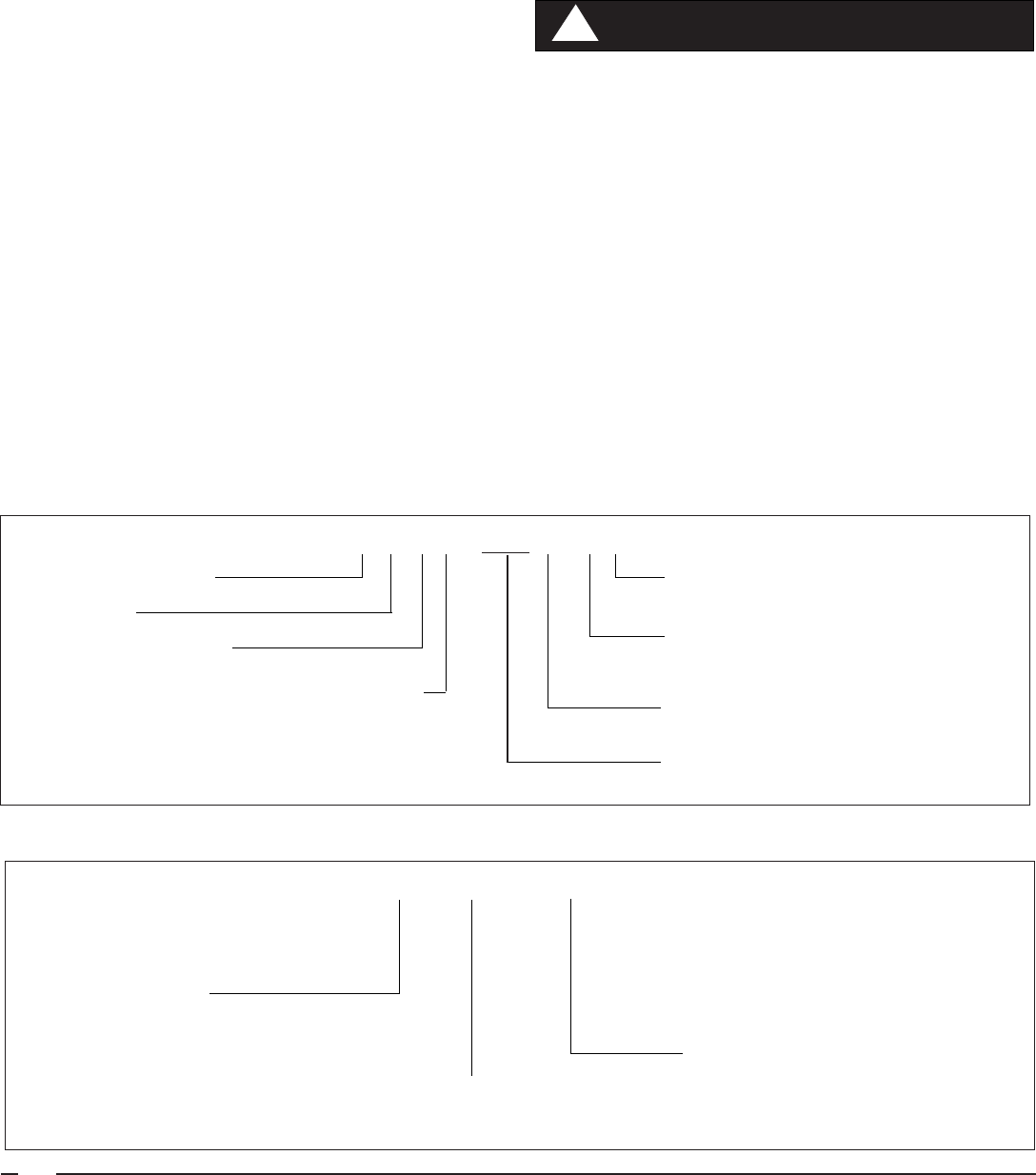
Combustion Motor Assembly Replacement
If, using the information from above, you have determined the
combustion motor assembly needs to be replaced,use the
following procedure:
1. Disconnect Molex plug and pressure switch hoses.
2. Remove screws from the top and break silicone loose
from orifice ring on top side of ventor assembly. (See
Figure 15). Inlet pipe may also break loose, this is normal.
3. Remove screws from bottom of assembly and remove
the whole assembly.
4. Mount new assembly, reattach screws removed in step 3
to bottom. Silicone around bottom, either before or after
installation of combustion air blower.
5. Re-silicone orifice ring and combustion air pipe and
reinstall screws removed in step 2 to top.
6. Reconnect Molex plug and pressure switch hoses from
step 1 and test.
Pressure Switch – The M1G 077-090 uses a differential type
pressure switch. The purpose of this switch is to insure that
a good supply of combustion air is supplied to the burner. The
combustion blower creates a differential in negative pressure
(less than atmospheric pressure) across the orifice ring. The
switch is normally open and closes on a drop in pressure, read
in negative inches of water column.
Picture 5. Fan and Limit Switch
Limit
Switch
Fan
Switch
Figure 15. Combustion Air Blower
Orifice
Ring
Silicone

19
Under normal operating conditions, once the ventor motor
builds up to speed sufficient differential (negative) pressure
(approximately -0.30” wc) will be created to close the differen-
tial pressure switch and keep it closed the whole heating
cycle. Under abnormal conditions, such as ventor motor
failure, or restricted air inlet or vent, sufficient differential
pressure will not be created.
Pressure switch check out procedure:
1. Remove orange wires from pressure switch. Place tees
in the bases connecting pressure switch to combustion
blower assembly.
2. Connect a differential pressure gauge (magnehelic or
equivalent) to the tees. The magnehelic connection
marked low connects to the lower tee, and the one
marked high connects to the top tee.
3. Start motor.
4. Negative pressure created by the forced draft motor must
be greater than -0.30” w.c. for the switch to close.
5. Use the ohm meter to check for continuity across the
switch.
6. If continuity is established, switch has closed. If ohm
meter shows infinite reading, and a pressure of -.30” w.c.
or higher is present, switch is open, and must be replaced.
If the pressure differential reading will not pull down to -.30”
w.c., possible causes could be:
1. Restriction in air inlet pipe, this causes a greater negative
at the inlet side connection. This will act to open switch. To
prove this, disconnect the hose going to the top connection.
If switch closes, there is too much negative pressure being
created on the inlet side. Look for air inlet restriction.
2. If there is a heat exchanger restriction or exhaust restriction
(any restriction after motor), it will cause a lack of negative
pressure. If flow out of chamber (exhaust) is poor no air
will be drawn in. Clean chamber and recheck.
3. If motor is not running, no negative will be created and
assembly will have to be replaced. (See combustion air
assembly replacement)
Burner Assembly – In order to perform procedures such as
inspecting for presence of LP gas in chamber, changing the
thermocouple, cleaning of pilot and burner, and inspecting the
heat exchanger, the burner assembly must be removed.
Changing Complete Burner Assembly
1. Gas Line - Remove the furnace door then disconnect and
remove the gas line from the valve body by using two
backup wrenches. Be careful not to damage the pipe
threads or introduce dirt into the gas line.
2. Wiring Leads - Remove the two low voltage wiring leads
from the valve body by carefully pulling them off the
connectors. Be careful not to damage or dirty the connector
ends.
3. Main Burner Mounting Plate- Using a philips screwdriver,
remove the screws that hold the main burner mounting
plate to the furnace.
4. Burner Assembly- Slide the burner assembly out from the
furnace.
5. Reverse procedure to reinstall.
NOTE: Be sure to install the gasket. If gasket becomes
damaged or torn, a replacement gasket kit is available.
Contact your distributor for part number.
Table 9. Lower (lesser) Differential Negative Pressure Than Closing Pressure
Insufficient negative pressure measured at the
combustion blower may be caused by:
1. Restriction on outlet side of combustion blower (blocked
flue or debris building up in flue).
2. Leak (lack of restriction) on inlet side. Inducer inlet
leaking, inducer blower props loose or not attached, or
wrong restrictor orifice.
3. To test for restriction in outlet pipe (exhaust) to verify
problem is outside of furnace, disconnect exhaust for
test period only and start furnace. If furnace starts, look
for problem in vent pipe. Reconnect after testing.
Higher than normal negative pressure at top
connection (acts to open switch) may be caused by:
1. Restricted combustion air inlet pipe.
2. To verify if problem is in inlet pipe, disconnect
pressure switch hose at top connection and start
furnace. If furnace starts, look for problems men-
tioned above in inlet pipe. Note: top connection acts
to open contacts on differential switch.
NOTE:
Inlet Pressure - Outlet Pressure = Differential Pressure
Lower (Lesser) Differential Negative Pressure Than Closing Pressure
Before removing burner assembly, shut off all gas
supply and electrical power to the furnace at the main
shut-off.
!
WARNING:

20
Gas Valve - The gas valves for the gas furnaces are a 100%
shut-off type and will fail safe if for some reason the gas is
turned off. The valve is a “step-open” type for M1G*-models
– which means it opens to a “low-fire” position, and after 14
seconds, “steps-open” to “high-fire.”
A small orifice is placed in the gas passage to delay the build
up of the working pressure. A minimum of two minutes pause
time is required between cycles to allow the orifice time to
exhaust all working gas from the diaphragm chamber and
obtain full dwell time on subsequent cycles. Factory set
nominal dwell time is approximately 14 seconds and is
not
field adjustable.
Testing Operating Pressure:
a. Remove furnace door and set the gas valve in the OFF
position.
b. Using a 3/16” Allen wrench, remove the plug from the right
side of the valve.
c. Install the barbed adapter in the plug hole. Tighten by
hand at first, then with an open end wrench. Do not
overtighten!
d. Install the hose and manometer to the barbed fitting. Be
sure to check all connections for leaks.
e. Light the pilot by following the instructions on the furnace
and set the gas valve switch to the ON position.
f. With the valve in the ON position, set the thermostat
above room temperature so the furnace will run throughout
the test procedure.
g. With the furnace operating, check for valve staging. The
operating pressure should be approximately 3.5” WC for
Natural Gas, 10” WC for LP gas.
Pilot Assembly, Thermocouple, and Venturi Burner
The pilot lights the main burner. The thermocouple generates
around 30 MV unloaded, (unscrewed from valve) and around
15 MV loaded (screwed into valve). See gas valve and pilot
outage section for troubleshooting.
The pilot orifice is not changed when furnace is converted to
LP (see conversion section). If the flame is more than about
1” in height, it can be adjusted using the pilot adjustment
screw. Turn the screw clockwise to decrease the flow rate,
counterclockwise to increase it. Note: Do not confuse the pilot
adjustment screw with the pressure regulator, which in-
creases by turning clockwise and decreases by turning coun-
terclockwise.
To clean pilot or service thermocouple or burner:
1. Remove burner.
2. Remove pilot assembly screws and pilot shield.
3. Remove pilot tube from pilot assembly.
4. Inspect pilot assembly - tap out pilot orifice and clean or
replace if plugged.
5. Replace the pilot tube, shield, assembly screws, and
burner. Re-start and test.
Figure 16. Burner Assembly with Venturi Assembly
Venturi
Assembly
Picture 7. Gasket
Picture 8. Burner Assembly
Picture 9. Pilot Assembly and Thermocouple
Pilot Assembly
Thermocouple

21
To change thermocouple:
1. Follow the same steps used to remove pilot assembly
2. Remove pilot tube close-off plate by removing the phillips
screw on the burner plate.
3. Note the height of the thermocouple in relationship to the
pilot before removal. It is critical to use the correct height
for reinstallation. Disconnect thermocouple from gas
valve and pilot assembly.
4. Slide thermocouple out through hole left after pilot close-
off plate was removed.
5. Reinstall new thermocouple and reverse steps from above.
Note: Use hand to tighten thermocouple in gas valve, plus
1/4” turn with wrench. Do not overtighten!
Venturi Burner Assembly
The burner assembly consists of the burner, venturi and
spreader. If burn through or other burner problem occurs,
follow these steps to replace the burner:
1. Follow the steps under changing burner assembly.
2. Disconnect pilot assembly by removing the two screws
holding pilot assembly and shield.
3. Remove the two phillips screws holding the burner from
the round burner plate. Note that one is removed from the
front side and one from the back side.
4. Remove burner and flame spreader assembly.
5. Install the new one by reversing steps 1 through 4.
6. Start up and test.
Gas Valve Replacement
1. Turn off gas and electric.
2. Disconnect the two low voltage wires.
3. Disconnect pilot tubing and thermocouple from gas valve.
4. Remove the two screws from the gas valve mounting
plate.
5. Remove gas valve and remove gas valve mounting.
6. Remove spud holder threaded into valve.
7. Repipe dope spud holder and tighten into new valve.
8. Reverse steps through 5 and test.
Fan Switch (Picture 5) – The fan switch is a temperature
actuated, normally open switch that closes on temperature
rise and is in series with the heating speed of the air circulating
blower. Upon a call for heat, and when the burner builds up
a supply of heat, the fan switch wraps closed at 115° (±5°) and
blower motor starts. After the thermostat opens and the
chamber cools down, the fan switch opens at 95° (±5°) and
blower shuts off.
If blower does not start after warm up, check blower for power.
If blower has power, see Blower Checkout section. If blower
does not have power, check for line voltage across the fan
switch. If voltage is present the switch is open. You also can
remove wires, and ohm out after warm up. NOTE: Use tape
to make sure wires do not touch anything. An infinity reading
indicates the switch is open.
If blower motor does not shut off and chamber has cooled (and
fan switch is off), check across fan switch contacts. If there is
no voltage, pull the single orange wire off (take care not to
touch uninstalled terminal or lay wire against metal). If blower
shuts off, fan switch is stuck closed. If switch does not close
or open properly, it will have to be replaced. Turn off power,
remove wires, and remove the two phillips screws to remove
switch. Install new switch and re-test.
Blower Assembly (Picture 10) – If the blower motor has
power to it (heating speed and neutral) and motor does not
start, motor has electrically opened up. NOTE: Some models
incorporate a capacitor, this should be checked first.
To replace motor:
1. Remove wires going to motor.
2. Remove Phillips screw(s) on left side.
3. Raise entire blower assembly slightly and swing out to left.
4. Loosen set screw on blower hub.
5. Remove screws holding motor to blower housing.
6. Remove motor and replace. NOTE: Some motors are
torsion-flex mount and some are band around mount. See
picture below.
7. Reverse steps 1-5 to reinstall. Note: Be sure to tighten
blower set screw on flat of motor shaft.
Band Around Mount
Picture 10. Blower Assemblies
Torsion Mount

22
Heat Exchanger Replacement – The heat exchanger is the
largest and most expensive item in the furnace. Before
replacing the heat exchanger, make certain it is the problem.
Call the technical service department if you have any uncer-
tainty about a heat exchanger failure. Heat exchangers can
become sooted up due to debris in top of furnaces,
improper conversion, or not being converted to LP. See
troubleshooting section on flue and conversion section of
this manual. This condition is not covered under warranty.
To Test Heat Exchanger:
Several methods may be used to test, or inspect for heat
exchanger flaws.
1. Remove the blower and burner. Visually inspect the heat
exchanger with a mirror. If you find a crack or hole in any
part of the heat exchanger, replace with out delay.
2. When the blower starts, observe the flame. If there is a
disturbance in the flame, inspect and determine the
cause.
3. Using a CO detector from the nearest register, monitor
the level for an increase while the unit runs. Single digits
of CO are common, but cigarette smoke, etc. can have an
impact on the level. A rapid increase in the CO level while
the furnace is running is not normal. If this occurs inspect
the heat exchanger.
Note: The furnace does not have to removed from its alcove
to replace the heat exchanger. Be sure to order the replace-
ment gasket kit along with the heat exchanger. It contains all
gaskets used in the furnace.
Change Out Procedure:
1. Disconnect all gas and electrical power to furnace.
2. Disconnect flue.
3. Remove burner assembly.
4. a. M1G-056-070 Only: Remove combustion air pipe.
b. M1G-077-090 Only: Remove combustion air pipe and
combustion blower.
5. Remove blower assembly.
6. Remove blower deck panel. NOTE: Panel will be difficult
to remove with furnace in alcove.
7. Remove front panel. NOTE: One of the panel screws is
located through the combustion air box on the right.
8. Lift up divider panel out of side cabinet lances.
9. Support the underside of the heat exchanger with a
board.
10. Remove top collector panel. NOTE: Two screws attach
through top of cabinet.
11. Remove the other eight screws in the top of the cabinet
that hold the combustion air box.
12. Remove heat exchanger and replace.
13. Reverse steps one through eleven to reinstall.
NOTE: Be sure to install all new gaskets (from gasket
replacement kit).
14. Start up and check out for proper operation.
Figure 17. Heat Exchanger
Roll Out Switch - (M1G* - 056 & 070) The furnace is
protected by a manual reset safety switch located on the
bottom left hand side of the combustion pipe. A draft imbal-
ance or improperly staging valve can cause this switch to
open up. Check for poor draft or blockage in the heat ex-
changer to correct draft imbalance.
Pilot Outage – Pilot outage can occur because of either a
mechanical (internal) or environmental (external) problem.
The frequency and conditions that exist will be important
information in solving a pilot outage problem. Most mechani-
cal problems will result in a situation where pilot can not be lit
at all or goes out with the first cycle or shortly thereafter. The
environment around the furnace or home will be trickier to
diagnose and usually will have infrequent occurrences of pilot
outage, such as once a week, only on windy days etc. Since
most pilot outage problems fall under one of these two
situations our troubleshooting will be divided up into these two
areas. See Pilot Outage chart, next page.

23
Pilot Outage Chart
Problem Possible causes Solutions
1.
Standard crown. Install optional all weather cap.
903656
2. Goes out only when it snows Install optional extension kit
901937
3. Install all weather cap.
903656
4. Install optional HSI conversion kit.
903428
Environmental (external to furnace)
Install optional extension kit to take
both inlet and exhaust above roof
peak.
Roof Jack termination too low, covering
inlet
All the above have been tried with no
resolution.
Goes out only when its windy or
Barometric pressure drops
suddenl
y
Goes out only in zero or sub-zero
weather
Conditions are such that pilot will
not sta
y
lit.
Roof jack termination too close to roof line,
causin
g
downdraft.
Ice forms around air inlet and blocks off
combustion air
Problem Possible causes Solutions
1. No pilot Flame No inlet gas pressure. Check sources.
Plugged pilot orifices. Clean or replace orifices.
2.
Thermocouple burned through. Replace thermocouple if defective.
Millivolts OK-Replace gas valve.
3.
Restricted air inlet or exhaust pipe. Clean out any debris.
No baffle prior to April, 1999. Install baffle kit.
903722
4. Gas valve not staging. Replace gas valve.
5. Gas valve closing improperly Replace valve
Pilot dirty or needs adjustment Adjust or clean pilot
Clean and or adjust pilot. Check inlet
g
as pressure.
Pilot lights OK, goes out when
main valve comes on or shortly
thereafter
Gas valve not staging or too high inlet gas
pressure.
Replace valve, lower gas pressure at
re
g
ulator or house.
Pilot lights with button held, but
g
oes out when released.
Pilot not contacting 3/8” to 1/2” top of
thermocouple.
Mechanical (Internal to Furnace)
Pilot goes out when main valve
comes on or shortly after, but
only on cold start-up- first cycle
onl
y
.
Pilot lights OK, goes out when
g
as valve closes (pulled out)
Check for proper millivolts - see
thermocouple section for procedure.

24
7038870
Figure 18. Gas Atmospheric Furnace, M1GH 056, 070 Models
ON/OFF
SWITCH
GAS VALVE
FAN SWITCH
HI-LIMIT
AUX. LIMIT
TRANSFORMER
L1 N
CR
24 V
115 V
WHITE
WHITE
WHITE
GRAY
BLUE
BLACK
GRAY
FAN ON/AUTO SWITCH
ORANGE
ORANGE
BLACK
L1
NEUTRAL
GROUND
SCREW
FURNACE ELECTRICAL BOX
BLACK
3A FUSE
BLOWER
MOTOR
HEATING
ONLY
654321
C
R
W
GRAY
RED
BLUE
CONNECTOR
HOUSING CAP
COMMON
FOR OPTIONAL
ACCESSORY KITS
BLACK
BLACK
LEGENDS
115V: FIELD 115V:
24V: FIELD 24V:
RED
NOTES
1. Incoming power must be polarized. Observe
color coding. (See furnace data label for
electrical information.)
2. If any of the original wires (as supplied with
the appliance) must be replaced, use 105˚C
Thermoplastic type wire or its equivalent.
BLACK
BLACK
SUPPLIED
BY INSTALLER
BLUE
WHITE
MANUAL RESET
VENT SWITCH
7038890
Figure 19. Gas Atmospheric Furnace, A/C Ready, M1G (B, C, D) 056, 070 Models
RED (LOW)
BLACK (HIGH)
BLUE (MED. HI)
ORANGE (MED. LO)
152
A/C
BLOWER
RELAY
364
ON/OFF
SWITCH
GAS VALVE
FAN
SWITCH
HI-LIMIT
AUX. LIMIT
TRANSFORMER
L1 N
CR
24 V
115 V
BLACK
ORANGE
BLUE
ORANGE
GREEN
WHITE
WHITE
WHITE
BLACK
GRAY
BLUE
BLUE
BLACK
VENT SWITCH
BLUE
FURNACE ELECTRICAL BOX
L1
NEUTRAL
GROUND SCREW
HEATING/
COOLING
C
R
G
W
HEATING/COOLING
RED
RED
(SEE NOTE)
TIE WIRE
CONNECTOR
HOUSING CAP
BLUE
GRAY
3A FUSE
GRAY
RED
654321
WHITE
654321
RED (LO)
BLACK
(HIGH)
WHITE
SUPPLIED
BY INSTALLER
LEGENDS
115V: FIELD 115V:
24V: FIELD 24V:
NOTES
1. Incoming power must be polarized. Observe color
coding. (See furnace data label for electrical
information.)
2. If any of the original wires (as supplied with the
appliance) must be replaced, use 105˚C
Thermoplastic type wire or its equivalent.
BLOWER
MOTOR
2 SPEED
BLOWER
MOTOR
4 SPEED
BLACK
BLACK
GRAY
GREEN
WHITE
MANUAL RESET
*
*M1G(C,D) Heating - replace orange wire with
red wire (low speed)
NOTE: To run at same speed in both heating and cooling mode,
remove wire from either terminal 4 or 6 on the relay, then attach
jumper to terminals 4 and 6.

25
Figure 21. Standing Pilot with Induced Draft Furnace, A/C Ready M1G (B, C, D) 077, 090 Models
654321
152
A/C
BLOWER
RELAY
364
152
COMBUSTION
BLOWER
RELAY
3
64
ON/OFF
SWITCH
GAS
VALVE
HI-LIMIT
AUX. LIMIT
TRANSFORMER
PRESSURE
SWITCH
COMBUSTION FAN
L1 N
CR
24 V
115 V
BLACK
BLACK
BLACK
BLACK
BLACK
ORANGE
ORANGE
GREEN
WHITE
WHITE
WHITE
WHITE
GRAY
GRAY
BLUE
BLUE
21
GRAY
L1
NEUTRAL
GROUND
SCREW
FURNACE ELECTRICAL BOX
RED
BLACK
BLUE
TIE WIRE
HEATING/
COOLING
BLUE
C
R
G
W
FAN
SWITCH
BLUE
RED*
CONNECTOR
HOUSING
GRAY
3A FUSE
GREEN
LEGENDS
115V: FIELD 115V:
24V: FIELD 24V:
NOTES
1. Incoming power must be polarized. Observe color
coding. (See furnace data label for electrical
information.)
2. If any of the original wires (as supplied with the
appliance) must be replaced, use 105˚C
Thermoplastic type wire or its equivalent.
BLOWER
MOTOR
SINGLE
SPEED
HEATING/COOLING
654321
RED (LOW)
BLACK (HIGH)
BLUE (MED. HI)
ORANGE
(MED. LO)
WHITE
BLOWER
MOTOR
4 SPEED
654321
RED (LOW)
BLACK (HIGH)
WHITE
CONNECTOR
HOUSING CAP
SUPPLIED
BY INSTALLER
*
Jumper Wire - M1GB Units Only
Otherwise Hi-Speed Connected
to Blower Relay
GRAY
RED
GREEN
WHITE
BLACK
BLACK
RED
BLOWER
MOTOR
2 SPEED
7038880
Figure 20. Standing Pilot with Induced Draft Furnace, M1GH 077, 090 Models
152
364
GAS VALVE
FAN
SWITCH
HI-LIMIT
AUX. LIMIT
PRESSURE
SWITCH
COMBUSTION
FAN
L1 N
CR
24 V
115 V
BLACK
BLACK
BLACK
BLUE
BLACK
WHITE
WHITE
WHITE
WHITE
GRAY
GRAY
BLUE
BLUE
21
GRAY
SUPPLIED BY
INSTALLER
FAN ON/AUTO
SWITCH
BLUE
BLACK
ORANGE
ORANGE
L1
NEUTRAL
GROUND
SCREW
FURNACE ELECTRICAL BOX
3A FUSE
BUSHING
RED
C
R
W
ON/OFF
SWITCH
CONNECTOR
HOUSING CAP
BLACK
BLACK
LEGENDS
115V: FIELD 115V:
24V: FIELD 24V:
GRAY
RED
WHITE
BLACK
BLACK
BLACK
TRANSFORMER
BLOWER
MOTOR
HEATING
ONLY
654321
BLACK
BLACK
NOTES
1. Incoming power must be polarized. Observe
color coding. (See furnace data label for
electrical information.)
2. If any of the original wires (as supplied with
the appliance) must be replaced, use 105˚C
Thermoplastic type wire or its equivalent.

26
Hot Surface Ignition System
Model M1M Furnace
Sequence of Operation
Troubleshooting
Wiring Diagrams

27
Call for heat,
t-stat closes R-W
Check for red light
on circuit board
24 Volt, C to W
on circuit board
Polarity
is reversed
Switch L1 & L2
Inducer starts
Check fuse on
circuit board,
replace if no
continuity
Check for voltage
at inducer molex plug
Pressure switch
stuck closed
Replace
Board
Replace
pressure switch
Circuit board 3 blinks
Check for voltage
at molex plug
Replace Inducer
Blower
Pressure switch
closes within
10 seconds
Circuit board
blinks 2 times
Is there >8mA on W terminal
of circuit board? Replace t-stat or
add isolation relay.
Pressure switch
open
Inducer pre-purges
for 45 seconds
Greater than
-.30" W.C.
differential at pressure switch
Replace pressure switch
Check venting
Ignitor heats up
and glows for
30 seconds
Gas valve open
Do Burners Light
Ignitor turns off 7 seconds
after gas valve opens
Main blower starts after
delay time (30 seconds)
Flame, inducer, main blower
stay on until call for heat ends
Replace ignitor
Replace circuit board
24 volts at gas valve.
Insure lever is in
ON position. Insure gas inlet
pressure is below 14" W.C.
Replace gas valve
Manifold Gas
Pressure Available
Burners stay on
longer than 6 seconds
Check and adjust ignitor
gap to 5/16"
Will retry 4 more times.
Soft lock out blinks 4 times
on status light.
Power down and
back up to reset.
Replace board
Flame light on
Replace circuit board
Check for voltage at
com and heat terminals
Replace circuit board
Yes
Yes
Yes
Yes
Yes
Yes
Yes
Yes
Yes
Yes
Yes
Yes
Yes
Yes
Yes
Yes
Yes
Yes
Yes
Yes
Yes
Yes
Check motor
and capacitor
Yes
No
No
No
No
No
No
No
No
No
No
No
No
No
No
Flashing
OFF
No
No
No
No
No
Is light blinking
5 times?
Adjust ignitor gap to 5/16"
Check ground circuit to
Furnace.
Flame light blinks at
1 uA(weak signal)
Note:
Retry
Every
Hour
Inducer post-purges
for 30 seconds
Main Blower Fan Off Timing
Troubleshooting Sequence – M1M

28
8. Hot Surface Ignition System
Model M1M
SEQUENCE OF OPERATION M1M SERIES
Call for heat: the thermostat calls for heat by energizing the
“W” terminal. The control checks to see the pressure switch
is open. If the pressure switch is closed when the call for heat
occurs, the control will begin to flash “3” on the Status LED
after 10 seconds and wait indefinitely for the pressure switch
to open.
Pressure switch proving: the control energizes the induced
draft motor and waits for the pressure switch to close. If the
pressure switch does not close within 10 seconds of the
inducer energizing, the control will begin to flash “2” on the
Status LED and wait indefinitely for the pressure switch to
close.
Pre-purge: the control runs the inducer for a 45 second pre-
purge time.
HSI warm up: the control energizes the HSI for 30 seconds.
The inducer remains energized.
Ignition activation period: the control energizes the main gas
valve for 6 seconds. The inducer and HSI remain energized.
Flame proving: the control de-energizes the hot surface
ignitor. The gas valve and inducer remain energized. If flame
is present 1 second after HSI de-energizes, the control goes
to blower on delay. If a flame is not present, the control de-
energizes the gas valve and proceeds with ignition retries as
specified below.
Blower on delay: If flame is present, the control energizes the
blower on HEAT speed 30 seconds after the gas valve
opened (24 seconds from HSI off). The gas valve and inducer
remain energized.
Steady heat: Control inputs are continuously monitored to
ensure limit and pressure switches are closed, flame is
established, and the thermostat call for heat remains.
Post purge: When the thermostat demand for heat is satisfied,
the control de-energizes the gas valves. The inducer output
remains on for a 30 second post-purge period.
Blower off delay: The indoor blower motor is de-energized
after a 120 second blower off delay. Blower timing begins
when the thermostat is satisfied.
COMPONENT PARTS
TROUBLESHOOTING
Polarity and Ground
The furnace will not operate if loss of ground occurs. Every
effort should be made at the installation to provide a good
ground. If old 2-wire romex exists it should be replaced with a
2-wire w/ground. A cold water line could be used provided that
the connection or grounding occurs before any di-electric
fittings and provided no plastic pipe is used inside or outside
the building.
Transformer (See Figure 21) – The transformer supplies
control voltage (24 vac) by stepping down the supply (pri-
mary) voltage from 115 vac to 24 vac (secondary voltage).
Transformers are rated by VA. VA is the volt/amp or total
wattage the secondary can handle. When a transformer is
replaced the VA should be of an equal or greater value.
Check-out procedure:
1. Using a volt/ohmmeter on at least 115 vac scale.
2. Measure the voltage on the control board terminals
"XFMR" & "NEUTRAL".
3. If voltage is 115 vac measure the voltage at terminals
marked "24 vac" & "Com" located in the center of the
control board.
4. If 115 vac is measured at "XFMR" & "NEUTRAL" but no
voltage is present at "24 vac" & "Com" replace transformer.
GROUND
NEUT.
HOT
OK
VOLTS AC
VOLTS DC
OHMS
MICRO
AMPS
Volts Com Prep
GROUND
NEUT.
HOT
HOT NEUTRAL
VOLTS AC
VOLTS DC
OHMS
MICRO
AMPS
Volts Com Prep
Polarity may be verified as follows:
1. Turn power supply "ON"
2. Using a voltmeter, check for
voltage between the hot (black)
and neutral (white) wire of
supply circuit.
3. Reading should be Line (Supply)
Voltage.
4. Check for voltage between the
neutral (white) wire and ground
wire of the supply circuit.
5. Reading should be zero volts (if
line voltage is read, polarity is
reversed).
6. Double check by checking for
voltage between the hot (black)
wire and ground wire of the
supply circuit.
Figure 22. Polarity and Ground
Picture 11. M1M Transformer

29
Transformers open on primary indicate low voltage short
circuit. Transformers open on secondary indicate an overload
(a current draw that exceeded rating).
Low Voltage Wiring
Install the thermostat per the manufacturer's instructions. The
low voltage (24 vac) connections from the thermostat are
made at the pigtail wires coming off the control board in the
furnace. See Figure 23 for the proper connections for heating
only (two-wire) and heating/cooling (four-wire) applications.
The recommended minimum wire gauge for thermostat wiring
is shown in Table 5.
The thermostat must not be installed on an outside wall or any
other location where its operation may be adversely affected.
Adverse effects include radiant loading from fireplaces, sun-
light, or lighting fixtures, and convective loading from warm air
registers or electrical appliances.
To check the heat anticipator setting:
Jump out R to W at thermostat with 10 Loop Helex and
measure current draw after blower starts. Divide by 10.
Example: 4 Amps = .4 set at .4.
Limit Control (Picture 14) – This furnace is protected by two
high temperature safety limit switches. The auxiliary (upper)
limit switch and the high temperature (lower) limit switch are
automatic reset types. If either limit trips, the burner will shut
off, and status light will flash “1”.
M1M-Control Board Replacement
Replace the control board only after determining a failure has
occurred in it. Most problems that are blamed on control are
actually external to control. (See troubleshooting section). If
control has failed, use the following procedure to replace.
1. Disconnect power to unit by turning off power switch.
2. Disconnect molex plugs and all push on terminal
connections. Note connections for rehook up.
3. After all wire connections have been removed you must
squeeze the four white stand offs to remove board. See
Pictures 13 showing board removed with exposed
standoffs remaining.
4. Carefully line up holes (Picture 12) on the new board over
standoffs, and push into place. Caution: push from
outside edge only - be careful of fragile components.
5. Reinstall all molex plugs and wires removed in step 2.
6. Apply power and re-test.
Ignition Control Troubleshooting
RED
Steady ON Control OK
Steady OFF No power
Rapid Flash False flame or internal control fault
1 Flash Limit switch is open
2 Flashes Pressure switch is open with inducer on
3 Flashes Pressure switch is closed with inducer off
4 Flashes Lockout due to failed ignition
5 Flashes 115 vac & neutral reversed or no ground
YELLOW
Steady ON Good Flame Signal
Blinking Weak Flame Signal
Steady OFF No Flame Signal
CONTROL LIGHT STATUS
Picture 14. Limit Switch
Picture 12. UTEC Ignition Control
Stand off
Holes
Picture 13. Ignition Board Removed
Stand offs

30
1. Power Line Polarity – The “hot” side of the power line
must be connected to the “L1” for the control to be able to
sense flame. The control detects the reversal of “hot” and
neutral. When L1 and Neutral are switched (or L1 is not
present), the control flashes “5” on the Status LED and
locks out.
2. Interrupted Thermostat – If the thermostat demand for
heat is removed before the flame recognition period, the
control will run the inducer for the post purge period and
de-energize all outputs.
3. Ignition Re-Try – If flame is not established on the first
trial for ignition period, the gas valve is de-energized and
the inducer remains energized for an inter-purge period of
30 seconds. The ignitor is then re-energized and the
control initiates another trial for ignition. This sequence
repeats for up to 5 trials for ignition.
4. Ignition Re-Cycle – Flame must not be sensed for 1
second before the control responds to a loss of flame. If
flame is established and maintained during the trial for
ignition period and then flame is lost, the gas valve is de-
energized within 2 seconds, the induced draft motor
continues to run, and the control begins timing the 45
second inter-purge delay. The indoor blower motor will be
energized and/or remain energized on heat speed for the
selected delay off time.
When the inter-purge delay is over, the ignitor is re-
energized, and the control initiates another ignitor warm
up and ignition activation period. The control will re-cycle
up to 5 flame losses (4 re-cycles) within a single call for
heat before going to lockout.
5. Call for Continuous Fan/Cooling – When a thermostat
call for continuous fan (G) without a call for heat or
cooling, the indoor fan is energized on the COOL speed
after a .25 second delay. If a call for heat (W) occurs
during continuous fan, the blower will de-energize.
A call for fan is ignored while in lockout.
6. Limit Switch Operation – Any time the limit switch
opens, the gas valve and ignitor will be de-energized, the
indoor blower motor will run on heat speed, and induced
draft motor will run continuously. Control status LED
flashes “1.”
When the switch re-closes, the induced draft motor will
run through post-purge and the indoor blower will run
through the selected fan off delay. The control will return
to normal operation after the blower off delay is completed.
7. Pressure Switch – The control shall ignore pressure
switch openings of less than 1 second (the gas valve will
momentarily de-energize while the pressure switch is
open, this may cause a loss of flame). To prevent pressure
switch faults from being treated as flame losses, the
control checks to see if the pressure switch has been
open momentarily within 2 seconds prior to the flame loss.
If the pressure switch was open any time within the 2
seconds prior to a flame loss, the control assumes the
flame loss was due to the open pressure switch and
responds as described below.
If the pressure switch opens for more than 1 second after
flame has been established, the control shall de-energize
the gas valve, run through a normal 30 second post-purge
and selected heat blower off delay. When the blower off
delay is complete, the control shall start an ignition
sequence if the thermostat is still calling for heat.
If the pressure switch opens for more than one second
during a pre-purge or inter-purge, the control shall wait for
the pressure switch to close. The purge time re-starts
when the pressure switch closes. The control status LED
will flash “2.” If the pressure switch is closed when the call
for heat occurs, the control will begin to flash “3” on the
status LED after 10 seconds and wait indefinitely for the
pressure switch to open.
8. Flame sense – Flame is normally sensed through the hot
surface ignitor using flame rectification. Open circuit
flame sense voltage should be approximately 120 VAC
line voltage. Minimum flame current required to sense
flame is 0.5 microamps DC. Normal microamps is 3 or
higher. To test, install microamp meter in series with
ground (9) pin. If flame light is on solid microamp signal is
at least 1 microamp. If flame light is blinking, flame signal
is between 0.5 and 1 microamp, indicating a weak signal.
Check for ignitor positioning and proper ground.
9. Undesired Flame – If flame is sensed longer than 4
seconds while the gas valve is de-energized, the control
shall energize the induced draft motor and indoor blower
on heat speed. When flame is no longer sensed, the
induced draft motor will run through post-purge and the
indoor blower motor will run through the selected heat fan
off delay time. The control will do a soft lockout, but will still
respond to open limit and flame. The Status LED will flash
rapidly when lockout is due to undesired flame.
10. Lockout – The control shall not initiate a call for heat or
call for continuous fan while in lockout. A call for cooling
operates as normal. The control will still respond to an
open limit and undesired flame.
Lockout will automatically reset after 1 hour. Lockout may
be manually reset by removing power from the control for
more than 1 second or removing the thermostat call for
heat for more than 1 and less than 20 seconds (The 20
second time limit prevents electronic thermostats from
automatically resetting lockout).
11. Power Interruption – The control will not interrupt its
operational sequence from power interruptions less than
80 mS in duration. Relay outputs will momentarily de-
energize during the interruption.

31
Power interruption greater than 80mS may cause the
control to interrupt the operating sequence and resume
as if power was first applied. All power interruptions of any
duration are to be self recovered and not result in a
condition that could cause lockout.
12. Control Internal Diagnostics
a.) Internal microprocessor tests: The software will
perform tests of the internal microprocessor hardware as
much as is practical. A detected failure in internal hardware
will result in lockout with the Status LED blinking rapidly.
b.) Flame sense circuitry diagnostics: The integrity of the
flame sense circuitry is constantly monitored by the
microcontroller. The control will lock out with the status
LED flashing rapidly if a fault is detected in the flame
sense circuitry.
c.) Failed gas valve relay: If the control senses the gas
valve output as energized when it should be de-energized,
and flame is not present, the control shuts off all control
outputs (including the inducer motor) to force the pressure
switch to open. If gas valve remains sensed as energized
15 seconds after the inducer shut off, the inducer is re-
energized to attempt to vent the uncontrollable gas.
If the control senses the gas valve output as energized
when it should be de-energized, and flame is present, the
control keeps the inducer motor and indoor blower motor
energized until flame is removed.
If the control does not sense that the gas valve is energized
when it should be, the control locks out with the Status
LED flashing rapidly.
Combustion Air Blower – All M1M models use a combustion
air blower incorporated in series with the air inlet pipe. Its
purpose is to supply a forced draft method of combustion air.
The quality of air is determined by the inlet orifice ring, located
on the inlet to the motor assembly.
Upon a call for heat under normal conditions, the combustion
blower starts up and supplies combustion air to the chamber.
If motor does not start, check to be sure call for heat is
established and fault light is on solid. See troubleshooting
flow chart and sequence of operation for further details. Then
disconnect blower molex plug and check for voltage at plug.
If voltage is available and motor does not start replace motor.
If power is not available check back through power source and
combustion blower relay contacts. See wiring diagram.
Picture 18. Blower Open Motor
Picture 17. Blower OHM
Picture 15. Combustion Air Blower
Figure 23. Combustion Air Blower
Orifice
Ring
Silicone
Picture 16. Blower Voltage

32
Combustion motor assembly replacement
Using the information from above you have determined the
combustion motor assembly needs to be replaced, follow the
outlined procedures.
1. Disconnect Molex plug
2. Remove screws from the top and break silicone loose
from orifice ring on top side of ventor assembly. Figure
Picture #26 inlet pipe may also break loose, this is
normal.
3. Remove screws from bottom of assembly and remove
the whole assembly.
4. Mount new assembly, reattach screws to bottom remove
from step 3.
5. Re-silicone orifice ring and combustion air pipe and
reinstall screws to top removed in step 2.
6. Reconnect Molex plug from step 1 and test.
Pressure Switch (Picture 19) – All M1M furnaces use a
differential type pressure switch. The purpose of this switch
is to insure that a good supply of combustion air is supplied
to the burner. The combustion blower creates a differential
in negative pressure (less than atmospheric pressure) across
the orifice ring. The switch is normally open and closes on a
drop in pressure, read in negative inches of water column.
Under normal operating conditions, once the ventor motor
builds up to speed sufficient differential (negative) pressure
(approximately -0.30” wc) will be created to close the differen-
tial pressure switch and keep it closed the whole heating
cycle. Under abnormal conditions, such as ventor motor
failure, or restricted air inlet or vent, sufficient differential
pressure will not be created.
Under most circumstances, when the pressure switch is not
going closed, insufficient differential (negative) pressure is not
being created. See Table 9 for opening and closing settings.
Pressure switch check out procedure:
1. Remove orange wires from pressure switch. Place tees
in the bases connecting pressure switch to combustion
blower assembly.
2. Connect a differential pressure gauge (magnehelic or
equivalent) to the tees. The magnehelic connection
marked low connects to the lower tee, and the one
marked high connects to the top tee.
3. Start motor.
4. Negative pressure created by the forced draft motor must
be greater than -0.30” w.c. for the switch to close.
5. Use the ohm meter to check for continuity across the
switch.
6. If continuity is established, switch has closed. If ohm
meter shows infinite reading, and a pressure of -.30” w.c.
or higher is present, switch is open, and must be replaced.
If the pressure differential reading will not pull down to -.30”
w.c., possible causes could be:
1. Restriction in air inlet pipe, this causes a greater negative
at the inlet side connection. This will act to open switch. To
prove this, disconnect the hose going to the top connection.
If switch closes, there is too much negative pressure being
created on the inlet side. Look for air inlet restriction.
Table 9. Lower (lesser) Differential Negative Pressure Than Closing Pressure
Insufficient negative pressure measured at the
combustion blower may be caused by:
1. Restriction on outlet side of combustion blower (blocked
flue or debris building up in flue).
2. Leak (lack of restriction) on inlet side. Inducer inlet
leaking, inducer blower props loose, or wrong restrictor
orifice.
3. To test for restriction in outlet pipe (exhaust) to verify
problem is outside of furnace, disconnect exhaust for
test period only and start furnace. If furnace starts, look
for problem in vent pipe. Reconnect after testing.
Higher than normal negative pressure at top
connection (acts to open switch) may be caused by:
1. Restricted combustion air inlet pipe.
2. To verify if problem is in inlet pipe, disconnect
pressure switch hose at top connection and start
furnace. If furnace starts, look for problems men-
tioned above in inlet pipe. Note: top connection acts
to open contacts on differential switch.
NOTE:
Inlet Pressure - Outlet Pressure = Differential Pressure
Lower (Lesser) Differential Negative Pressure Than Closing Pressure
Picture 19. Pressure Switch
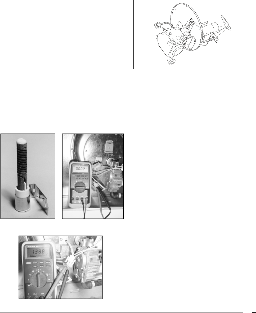
33
2. If there is a heat exchanger restriction or exhaust restriction
(any restriction after motor), it will cause a lack of negative
pressure. If flow out of chamber (exhaust) is poor no air
will be drawn in. Clean chamber and recheck.
3. If motor is not running, no negative will be created and
assembly will have to be replaced. (See combustion air
assembly replacement)
Hot Surface Ignitor – The hot surface ignitor is helical in
shape and is located approximately 5/16" in front of the
burners. Its function is to ignite fuel at the appropriate time in
the sequence. The hot surface ignitor used is manufactured
by CARBORUNDUM.
NOTE: Special care should be taken when handling the ignitor.
You should never touch the ignitor surface. Grease or dirt from
your hands will shorten the ignitor's life.
Check-out Procedure:
1. Unplug ignitor from 2-prong plug.
2. Place a voltmeter on the proper scale (at least 115 vac).
3. Establish a call for heat.
4. After approx. 45 seconds of induced draft motor operation,
the ignitor should see line voltage.
5. If voltage is present, replace the ignitor. (See Figure 41.)
6. If no voltage is present, replace control board.
7. The ignitor may also be ohmed out. The ignitors usually
range from 125 to 150 ohms at 70°F/21°C.
8. Be sure when replacement ignitor is installed that it is
approximately 5/16" from the burners. Mishandling and
misalignment are the primary causes of ignitor failure.
Picture 20. Hot Surface
Ignitor
Picture 21. Ignitor and
Voltmeter
Picture 22. Test Hot Surface Ignitor
Figure 24. M1M Burner Assembly
Burner Assembly – In order to perform procedures such as
inspecting for presence of LP gas in chamber, cleaning
burner, and inspecting the heat exchanger, the burner assem-
bly must be removed.
Changing Complete Burner Assembly
1. Gas Line - Remove the furnace door then disconnect and
remove the gas line from the valve body by using two
backup wrenches. Be careful not to damage the pipe
threads or introduce dirt into the gas line.
2. Wiring Leads - Remove the two low voltage wiring leads
from the valve body by carefully pulling them off the
connectors. Be careful not to damage or dirty the connector
ends.
3. Main Burner Mounting Plate- Using a philips, remove the
screws that hold the main burner mounting plate to the
furnace.
4. Burner Assembly- Slide the burner assembly out from the
furnace.
5. Reverse procedure to reinstall.
NOTE: Be sure to install the gasket.
Gas Valve - The gas valves for the gas furnaces are a 100%
shut-off type and will fail safe if for some reason the gas is
turned off.
When the thermostat calls for heat, the first and second valves
open by the energization of two solenoids. If 24 vac is
available at valve and no gas flows, valve is defective. NOTE:
Be sure gas pressure is available at the inlet to the valve and
does not exceed 14” w.c. (1/2 lb.). If this condition exists, valve
will lock down and no gas will flow through it.
Step Flow: during the dwell time, there is no flow through the
main valve since it is closed. A calibrated bypass hole provides
step flow, for soft ignition and draft build up, during the dwell
time. The bypass flow can be custom tailored from 40% to 70%

34
of full flow, but is also
not
field adjustable. At the end of the dwell
time, the main valve opens, allowing full gas flow.
Testing Operating Pressure:
a. Remove furnace door and set the gas valve in the OFF
position.
b. Using a 3/16” Allen wrench, remove the plug from the right
side of the valve.
c. Install the barbed adapter in the plug hole. Tighten by
hand at first, then with an open end wrench. Do not
overtighten!
d. Install the hose and manometer to the barbed fitting. Be
sure to check all connections for leaks.
e. Set the gas valve switch to the ON position.
f. With the valve in the ON position, set the thermostat
above room temperature so the furnace will run throughout
the test procedure.
g. With the furnace operating, check for valve staging. The
operating pressure should be 3.5” WC for Natural Gas,
10” WC for LP gas.
Blower Assembly – If the blower motor has power to it
(heating speed and neutral) and motor does not start, motor
has electrically opened up. NOTE: Some models incorporate
a capacitor, this should be checked first.
To replace motor:
1. Remove wires going to motor.
2. Remove single Phillips screw in upper left corner.
3. Raise entire blower assembly slightly and swing out to left.
4. Loosen set screw on blower hub.
5. Remove screws holding motor to blower housing.
6. Remove motor and replace. NOTE: Some motors are
torsion-flex mount and some are band around mount. See
picture below.
7. Reverse steps 1-5 to reinstall. Note: Be sure to tighten
blower set screw on flat of motor shaft.
Heat Exchanger Replacement – The heat exchanger is the
largest and most expensive item in the furnace. Before
replacing the heat exchanger, make certain it is the problem.
Call the technical service department if you have any uncer-
tainty about a heat exchanger failure. Heat exchangers can
become sooted up due to debris in top of furnaces,
improper conversion, or not being converted to LP. See
troubleshooting section on flue and conversion section
of this manual. This condition is not covered under
warranty. See page 22 of this manual – To Test Heat
Exchanger.
Note: The furnace does not have to removed to replace the
heat exchanger.
Change Out Procedure:
1. Disconnect all gas and electrical power to furnace.
2. Disconnect flue.
3. Remove burner assembly.
4. Remove combustion air pipe and combustion blower.
5. Remove blower assembly.
6. Remove blower deck panel. NOTE: Panel will be difficult
to remove with furnace in alcove.
7. Remove front panel. NOTE: One of the panel screws is
located through the combustion air box on the right.
8. Lift up divider panel out of side cabinet lances.
9. Support the underside of the heat exchanger with a
board.
10. Remove top collector panel. NOTE: Two screws attach
through top of cabinet.
11. Remove the other eight screws in the top of the cabinet
that hold the combustion air box.
12. Remove heat exchanger and replace.
13. Reverse steps one through eleven to reinstall.
NOTE: Be sure to install all new gaskets (from gasket
replacement kit).
14. Start up and check out for proper operation.
Picture 23. Blower Assemblies
Band Around Mount
Torsion Mount
Figure 25. Heat Exchanger

35
ORANGE
BLOWER
MOTOR
SINGLE
SPEED
ON/OFF
SWITCH
C
R
G
W
GAS VALVE
HI-LIMIT
AUX. LIMIT
TRANS-
FORMER
PRESSURE
SWITCH
654321
654321
COMBUSTION FAN
L1 N
CR
24 V
115 V
21
1
4
5
2
6
3
1
2
3
4
5
6
7
8
9
IGNITOR
BLUE
BLUE
BLACK
GREEN
YELLOW
YELLOW
BLACK
BLACK
ORANGE
ORANGE
BLACK
WHITE
L1
NEUTRAL
GROUND SCREW
FURNACE ELECTRICAL BOX
24V
NEU
C
H
L1
XFRM
TIE
WIRE
RED
BLACK
BLUE
CONNECTOR
HOUSING CAP
GROUND
SCREW
BLACK
BLACK
CONTROL LIGHT STATUS
RED YELLOW
Steady ON Control OK Steady ON Good Flame Signal
Steady OFF No power Blinking Weak Flame Signal
Rapid Flash False flame or internal control fault Steady OFF No Flame Signal
1 Flash Limit switch is open
2 Flashes Pressure switch is open with inducer on
3 Flashes Pressure switch is closed with inducer off
4 Flashes Lockout due to failed ignition
5 Flashes 115 vac & neutral reversed or no ground
CONTROL
LIGHTS
RED
Jumper must be
removed if converting
to a multispeed blower.
Jumper is required for
M1MA models and
M1MB 077, 090
BLACK
WHITE
WHITE
BLACK
BLACK
GREEN
RED
GRAY
WHITE
BLACK (HIGH)
RED (LO)
WHITE
RED (LO)
BLACK (HIGH)
BLUE (MED. HI)
ORANGE (MED. LO)
WHITE
654321
LEGENDS
115V: FIELD 115V:
24V: FIELD 24V:
BLOWER
MOTOR
2 SPEED
BLOWER
MOTOR
4 SPEED
NOTES
1. Incoming power must be polarized. Observe color
coding. (See furnace data label for electrical
information.)
2. If any of the original wires (as supplied with the
appliance) must be replaced, use 105˚C Thermoplastic
type wire or its equivalent.
SUPPLIED
BY INSTALLER
C W G R
COM
BLUE
WIRING DIAGRAM
7038540
Figure 25. Gas Direct Ignition Furnace, Heating & A/C Ready - All M1M Models

UTEC M1 FURNACE CONTROL SEQUENCE
Start-Up / Shut-Down
Thermostat on
call for heat
(R to W)
Event
Inducer
Igniter
Main Blower
Flame Proving
Gas Valve
Main Blower
Gas Valve
Factory Set
at 120 seconds
Elapsed Time Line - Seconds
Thermostat Off
(Break R to W)
Inducer
0
30
1200
45
81
75
82
112
NORMAL START-UP SEQUENCE
Elapsed Time Line - Seconds
NORMAL SHUT-DOWN SEQUENCE
Normal Start-Up:
1. Close R to W circuit. The inducer motor is energized.
2. After a 45 second pre-purge the igniter is energized.
3. After a 30 second heat up the gas valve is energized (The igniter remains on during
the first 6 seconds. Gas valve will be de-energized at 7 seconds if flame is not proved.)
4. After 30 seconds the main blower is energized. (Total elapsed time 105 seconds).
Normal Shut-Down:
1. Break R to W circuit.
2. After 30 seconds the inducer is turned off.
3. After 90 seconds the main blower is turned off (120 seconds after gas valve).
St. Louis, MO
690A-0999 (Replaces 690A-0998)
Specifications and illustrations subject to change
without notice and without incurring obligations.
Printed in U.S.A. (09/99)
®
®
C
