
Agile Requirements Designer 3.3

Agile Requirements Designer 3.3
Table of Contents
Release Notes.......................................................................................................................................6
What's New in 3.3.............................................................................................................................................................6
Agile Requirements Designer Hub-Studio Compatibility.............................................................................................9
Acknowledgments and License Agreements................................................................................................................9
Product Accessibility Features.......................................................................................................................................9
Getting Started................................................................................................................................... 12
Overview.......................................................................................................................................................................... 14
Agile Requirements Designer Knowledge Base.........................................................................................................16
Agile Requirements Designer Learning Resources................................................................................................... 17
Role in the Complete Continuous Testing Platform.................................................................................................. 20
Troubleshooting..............................................................................................................................................................20
Installing.............................................................................................................................................. 26
ARD Installation Overview............................................................................................................................................ 26
Verify ARD Installation Prerequisites........................................................................................................................ 27
Install ARD Hub Using a Docker Container............................................................................................................. 29
Install SSL Certificates for ARD Hub in Docker................................................................................................ 31
Install ARD Hub Services Using a Windows Installer.............................................................................................. 33
Install Plugin Framework and Telemetry Services............................................................................................ 33
Install ARD Hub Using Podman Container.............................................................................................................. 33
Install ARD Hub Manually.........................................................................................................................................36
Install SSL Certificates for ARD Hub Manually.................................................................................................41
Upgrade, Reconfigure, or Back-Up ARD Hub..........................................................................................................44
Add Users to ARD Hub............................................................................................................................................ 50
Install ARD Studio Manually..................................................................................................................................... 52
Install ARD Studio Without User Interaction (Silent Installation).......................................................................53
Configure the License................................................................................................................................................... 54
Manage Administrator Account and Password.......................................................................................................... 55
Enable Standard Settings and Advanced Features (ARD Studio)............................................................................ 55
Requirements Modeling.....................................................................................................................59
Visual Flows....................................................................................................................................................................60
Create Visual Flows....................................................................................................................................................... 62
Add a Decision Block................................................................................................................................................64
Add a Process Block................................................................................................................................................ 64
Edit Block Properties.................................................................................................................................................65
Copy, Duplicate, or Clone Blocks............................................................................................................................. 69
Build Complex Models Using Subflows and Loops..................................................................................................69
2

Agile Requirements Designer 3.3
Parameterize Flows and Script Generation..............................................................................................................74
Add and Modify Text Labels and Arrows................................................................................................................. 77
Compare Flow Diagram Revisions........................................................................................................................... 78
Model Multiple Dependent Decisions Using Decision Tables...................................................................................78
Define Custom Fields................................................................................................................................................80
Deduplicate Existing Test Cases..................................................................................................................................83
Automatic Model Building Accelerator........................................................................................................................85
Generate Non-Sequential Scripts Using Dynamic Configuration............................................................................. 87
Cost, Complexity and Coverage...................................................................................................................................90
Constraints...................................................................................................................................................................... 92
Use Pins to Highlight Paths or Items.......................................................................................................................... 94
Filter Blocks by Properties........................................................................................................................................... 95
Modeling Best Practices................................................................................................................................................95
How to Model Boolean Logic..................................................................................................................................... 100
How to Model Assertions............................................................................................................................................101
Flow Management............................................................................................................................ 108
Manage Flow Projects in ARD Hub............................................................................................................................109
Manage Flows in the TDM Repository.......................................................................................................................113
Manage Flows in Your Local File System................................................................................................................. 114
Migrate Flows Into ARD Hub...................................................................................................................................... 114
Requirements Insight.......................................................................................................................116
Log Into the Web Interface......................................................................................................................................... 116
Manage Flow Projects in the Web Interface............................................................................................................. 116
Visualize Flow Dependencies..................................................................................................................................... 118
Manage ARD Hub Users Roles and Projects............................................................................................................120
Test Generation................................................................................................................................ 125
Path Explorer................................................................................................................................................................ 125
Optimization Techniques............................................................................................................................................. 128
Store Paths....................................................................................................................................................................132
Filter Paths.................................................................................................................................................................... 137
Populate Custom Path Collections............................................................................................................................ 138
Risk-Based Test Case Generation..............................................................................................................................140
Log Test Case Results.................................................................................................................................................141
Managing Test Data......................................................................................................................... 142
Make and Find Data..................................................................................................................................................... 144
Make and Find Data at Test Execution Time............................................................................................................ 145
Use Test Data Manager Actions in ARD....................................................................................................................148
Integrations....................................................................................................................................... 149
Using Plugin Framework............................................................................................................................................. 151
3

Agile Requirements Designer 3.3
Configure Dynamic Data Resolution For Export...................................................................................................... 153
Import and Export Visual Flows................................................................................................................................. 153
Export to Word............................................................................................................................................................. 155
Export to Word Using Templates............................................................................................................................... 155
Export to Excel Using Templates............................................................................................................................... 157
Export to Service Virtualization..................................................................................................................................163
Import Rich Text........................................................................................................................................................... 164
Import From Excel or CSV.......................................................................................................................................... 165
Import and Export XML or JSON............................................................................................................................... 167
Import Automation Scripts (Ranorex, Eggplant)...................................................................................................... 168
Integrate With BlazeMeter........................................................................................................................................... 168
Configure BlazeMeter Integration........................................................................................................................... 170
Integrate with SAP Solution Manager........................................................................................................................171
Integrate With Application Test (DevTest Solutions)............................................................................................... 172
Integrate With TurnKey................................................................................................................................................ 174
Integration With Lifecycle Tools................................................................................................................................. 175
Configure Lifecycle Tool Integration........................................................................................................................178
Integrate With Rally.................................................................................................................................................181
Integrate With Micro Focus ALM (REST)...............................................................................................................182
Integrate With HPE ALM (GT HPE ALM Service)................................................................................................. 184
Integrate With JIRA.................................................................................................................................................185
Integrate With Tricentis qTest..................................................................................................................................187
Integrate With Microsoft Team Foundation Server and Azure DevOps Services...................................................188
Test Automation............................................................................................................................... 191
Automation Scripts Examples.................................................................................................................................... 192
Define Your Automation Configuration......................................................................................................................193
Construct Scripts from a Model................................................................................................................................. 197
How to Use Variables.................................................................................................................................................. 200
Drag and Drop Automation Steps Onto the Canvas................................................................................................203
Import and Export Snippets From Keyword-Driven Spreadsheets........................................................................ 206
Manage Automation Configuration Files...................................................................................................................207
BlazeMeter Automation................................................................................................................................................209
Reference.......................................................................................................................................... 213
ARD Hub User Roles and Permissions..................................................................................................................... 213
Automation Keywords................................................................................................................................................. 214
Data Painter Functions................................................................................................................................................ 217
Install HPE ALM Service............................................................................................................................................. 219
Path Naming Template Functions.............................................................................................................................. 221
Usage Data (Telemetry)................................................................................................................... 224
4


Agile Requirements Designer 3.3
Release Notes
The online version of the Release Notes contains the latest updates.
This page summarizes the new or updated functionalities and known issues. If you have questions, contact the Agile
Requirements Designer Community forum.
For more information, refer to the following sections:
•
What's New in 3.3
•
Agile Requirements Designer Hub-Studio Compatibility
•
Acknowledgments and License Agreements
•
Product Accessibility Features
What's New in 3.3
This page summarizes the new or updated functionalities and known issues. If you have questions, contact the Agile
Requirements Designer Community forum.
New Features
Integrate with any tool using the API
The latest version of Agile Requirements Designer comes with a powerful plugin framework that enables you to
seamlessly connect to your target applications and manage items within them. With this feature, you can easily create,
update, and delete user stories, tasks, defects, and other work items in your test case management systems and test
frameworks. Additionally, you can generate tests in the form of JCLs to execute on the mainframe and even create other
types of items using the plugin framework.
The Agile Requirements Designer plugin framework is highly customizable, allowing you to update existing plugins or
develop new ones that meet your specific integration needs. The framework fully supports the creation, updating, and
deletion of items based on the paths generated in ARD. All operations are customizable in the plugin. For instance, if you
generate a test case based on a path, the plugin framework can generate test case steps based on the blocks visited in
the path.
With mapping that is the same as for other integrations, the plugin framework allows for customization of mapping,
including hardcoding of values or transformations. With these powerful features, Agile Requirements Designer makes it
easy to manage and integrate with your target applications.
For more information, refer to Using Plugin Framework or Plugin Developer Guide.
Use of ARD Automation functions to generate export content
The Agile Requirements Designer now enables users to easily map Automation output to any exported attribute of the
path. This functionality allows for greater flexibility in how users can customize their test case management process. For
instance, you can now easily map your Gherkin automation scripts to serve as the description of your test case, or you
can choose to add an additional Automation Layer that you would like to export to a particular field and add an additional
description of the test case. With this new capability, users can streamline their testing process and achieve greater
efficiency in their software development cycle.
For more information on how to configure a custom field to enable such exports, refer to Manage Path Automation Script
Fields.
6

Agile Requirements Designer 3.3
Identify Exported Paths
With this feature, users can now easily see all the path links in one place, making it much easier to check work items
before updates. This feature provides a more streamlined experience, allowing users to quickly get all the links for
exported items and reduce the risk of errors when updating.
Generate automation scripts without user interaction
Introducing our automation generation in CLI mode that enables users to generate automation without the need to launch
a user interface. This feature offers a convenient way to refresh your automation scripts and test data, ensuring that
they are always up-to-date and accurate. With easy setup, users can seamlessly integrate this feature into their existing
pipelines to get a new set of data for their automation scripts, saving them valuable time and effort.
For more information refer to, command-line tool.
Find flow stored in ARD Hub by name
The feature allows users to search for ARD Flows stored in ARD Hub by name. With this feature, users can easily find all
the flows that match a specific name pattern and display them in a folder structure or open them in ARD for later use.
For more information, refer to Flow Search.
7

Agile Requirements Designer 3.3
Force ARD path by enhanced manual path building
We've enhanced manual path building, making it easier to generate custom paths. Simply select the desired segment and
click "Find Path" to automatically create a start-to-end path including your selection.
8

Agile Requirements Designer 3.3
Miscellaneous
•
Double-clicking on the row corresponding to an automation step will open the Edit Automation Step dialog. This
can be done in various locations including the automation tab of the block properties dialog and the automation
configuration dialog.
•
ARD Hub installation is now possible on RHEL 8 and RHEL 9. For more information, refer to Install ARD Hub using
the Podman Container.
•
When you install ARD Studio manually in the UI mode, you can now configure Telemetry. For more information, refer to
Install ARD Studio Manually.
•
The Path Impact Analyzer dialog now alerts users to broken paths before opening the Test Data and Export
Automation dialogs, allowing for analysis of changes before exporting.
•
ARD Hub generates the audit log of permission assignments.
•
Step joins which are defined for the automation layer and are included only between defined steps.
•
Unsupported Visual C++ redistributables were removed from the installation.
•
Keycloak was upgraded to version 20.0.5.
Agile Requirements Designer Hub-Studio Compatibility
The following table shows which releases of ARD Hub are compatible with which releases of ARD Studio.
Compatibility Matrix ARD Studio 3.3 ARD Studio 3.2 ARD Studio 3.1
Hub 3.3 Yes Yes Yes
Hub 3.2 No Yes Yes
Hub 3.1.* No No Yes
Acknowledgments and License Agreements
Agile Requirements Designer uses third-party software in accordance with the terms and conditions for use,
reproduction, and distribution as defined by the applicable license agreements. To view the Third-Party Software License
Acknowledgements, download the respective TPSA file from the following list:
•
Agile_Requirements_Designer-ARD_Hub-release_3.3
•
Agile_Requirements_Designer-ARD_Studio-release_3.3
•
ARD_3.3_TPSA
Product Accessibility Features
Broadcom/CA Technologies is committed to ensuring that all customers, regardless of ability, can successfully use its
products and supporting documentation to accomplish vital business tasks.
You can use the following accessibility features with Agile Requirements Designer:
Display
To increase visibility on your computer display, you can adjust the following options:
•
Font style, color, and size of items
Defines font color, size, and other visual combinations.
•
Screen resolution
Defines the pixel count to enlarge objects on the screen.
•
Cursor width and blink rate
9

Agile Requirements Designer 3.3
Defines the cursor width or blink rate, which makes the cursor easier to find or minimize its blinking.
•
Icon size
Defines the size of icons. You can make icons larger for visibility or smaller for increased screen space.
Sound
Use sound as a visual alternative or to make computer sounds easier to hear or distinguish by adjusting the following
options:
•
Volume
Sets the computer sound up or down.
•
Text-to-Speech
Sets the computer's hear command options and text read aloud.
•
Warnings
Defines visual warnings.
•
Notices
Defines the aural or visual cues when accessibility features are turned on or off.
•
Schemes
Associates computer sounds with specific system events.
Keyboard
You can make the following keyboard adjustments:
•
Repeat Rate
Defines how quickly a character repeats when a key is struck.
•
Tones
Defines tones when pressing certain keys.
•
Sticky Keys
Defines the modifier key, such as Shift, Ctrl, Alt, or the Windows Logo key, for shortcut key combinations. Sticky keys
remain active until another key is pressed.
Mouse
You can use the following options to make your mouse faster and easier to use:
•
Click Speed
Defines how fast to click the mouse button to make a selection.
•
Click Lock
Sets the mouse to highlight or drag without holding down the mouse button.
•
Reverse Action
Sets the reverse function controlled by the left and right mouse keys.
•
Blink Rate
Defines how fast the cursor blinks or if it blinks at all.
•
Pointer Options
Let you complete the following actions:
–
Hide the pointer while typing
–
Show the location of the pointer
–
Set the speed that the pointer moves on the screen
–
Choose the pointer's size and color for increased visibility
–
Move the pointer to a default location in a dialog box
10

Agile Requirements Designer 3.3
Keyboard Shortcuts
The following table lists the keyboard shortcuts that Agile Requirements Designer supports:
Keyboard Description
Ctrl+X Cut
Ctrl+C Copy
Ctrl+K Find Next
Ctrl+F Find and Replace
Ctrl+V Paste
Ctrl+S Save
Ctrl+Shift+S Save All
Ctrl+D Delete Line
Ctrl+Right Next Word
Ctrl+Down Scroll Line Down
End Line End
11

Agile Requirements Designer 3.3
Getting Started
Agile Requirements Designer is a sophisticated testing tool that uses the concepts of model-based testing to provide
end-to-end support for requirements gathering, test design, test creation, test automation, and more. While you can get
started modeling flows and integrating with the other testing tools in your tool chain right away, you will get more out
of the product by taking the time to understand the concepts behind model-based testing and the full power of Agile
Requirements Designer.
Introduction
New to Agile Requirements Designer? The ARD overview demo summarizes the business value of Agile Requirements
Designer and provides a full product demo to get you started.
ARD Expert Webcast Series (2019)
In the following webcast series, testing experts show how they use ARD for cooperative test design and management, test
data usage, generation of automation scripts, API testing, and more.
•
ARD Best Practices to Achieve Value – Part 1
•
ARD Best Practices to Achieve Value – Part 2
•
Test Design Management with ARD Hub
•
Test Data in Agile Requirements Designer
•
Automation in Agile Requirements Designer
•
Model-Based Testing & Behavior Driven Development (BDD)
•
Model Driven API Testing
•
Date Driven Testing with Agile Requirements Designer
•
API Test Design with Model-Based Testing
TIP
Bookmark our Modeling Best Practices: This article describes requirements design approaches, keyboard
shortcuts, bulk editing, and How to Model Boolean Logic, as recommended by ARD experts.
Getting Started with CA Agile Requirements Designer (2017)
These videos are part of an on-boarding experience produced by test consultant Paul Gerrard. This video series shows
in detail how Agile Requirements Designer can be used to model requirements and systems to support collaboration and
testing in software projects.
Introduction
Model-Based Testing
The following video provides an introduction to the thought process behind model-based testing:
The following video provides an introduction to models themselves and how you can use them in testing to collaborate:
ARD Concepts
The following video introduces key Agile Requirements Designer concepts and more detailed modeling techniques:
12

Agile Requirements Designer 3.3
CA ARD and Model-Based Testing
The following video shows how to create basic models in Agile Requirements Designer:
The following video shows how to create a model of a GUI-based application using requirements and common UI
constructs:
Create Tests from Requirements-Based Models
Create Test Cases from a Model
The following video shows how to add the necessary data and expected results to a model to create a test case:
Coverage Criteria
The following video shows how to generate test cases based on the level and type of test coverage that you require:
All-Pairs Testing
The following video shows how you can configure your models to support the all-pairs testing technique:
UI Testing
The following video shows how to create a model of a user interface interaction to validate front end functionality:
Web Service Modeling
The following video shows how to model and test web service calls:
Simple Decision Tables
The following videos shows how you use decision tables to model system behavior that depends on the outcome of
multiple decisions:
Modeling Loops and Iterative Test Design
The following video shows how to build loops into your models where required for iterative and incremental test design:
End-to-End Tests and Sub Processes
The following video shows how you can use sub-processes to model a series of transactions within a larger controlling
process:
Using Filters
The following videos shows how to use filters to query models, paths through each model, and stored paths:
ETL Testing
The following video shows how to create models to effectively support extract, transform, and load testing:
13

Agile Requirements Designer 3.3
This concludes the Paul Gerrard getting started video series. More videos for other Agile Requirements Designer use
cases are available in the following places:
•
On the top level pages on this site (Techdocs), which represent major product usage categories, such as modeling,
integrations, and automation
•
Within each individual documentation page on this site where a video applies to documented functionality
Overview
Agile Requirements Designer helps Business Analysts to define unambiguous requirements, and assists Testers with the
efficient creation test cases, and automated tests. Developers can plug Agile Requirements Designer into their existing
test management tools (such as HPE Application Lifecycle Management and CA LISA), and link test cases with relevant
test data and expected results. Advanced optimizations help eliminate overtesting, so Testes can run tests prioritized by
criticality.
Why is this important? Each defect impacts quality and value of the product, and defect fixing causes delays. Yet most
defects can be traced back to errors in the requirements, and the subsequent test case design and data provisioning.
For more use cases and expert videos, see Agile Requirements Designer For Agile Use Cases.
Agile Requirements Designer helps various users achieve their business goals:
•
Software Testers
Software testers can quickly define functional logic flows and verify them with the end user or business
analyst. From that flow, they can automatically derive and maintain the smallest set of test cases needed to verify the
program. They can link tests directly to the correct data and expected results, which reduces the manual effort of using
spreadsheets, and shortens test cycles.
•
Software Programmers
Programmers verify processes with the Business Analyst before coding, and work with Testers to clearly define test
cases.
•
Business Analysts
Agile Requirements Designer provides greater clarity when collaborating with users and technical teams. Business
analysts can use it to map requirements to clear, visual flow charts, while also providing metrics to estimate project
time and costs more accurately.
•
Chief Information Officers
Agile Requirements Designer transforms the CIO's ability to improve quality: It helps analyze requirements and change
requests, predicting how long development and testing will take.
Architecture and Installation
You can deploy Agile Requirements Designer in two ways:
•
Installation together with Test Data Manager
Get the full functionality of the TDM repository integration which can help you find or make test data, including Test
Matching and Data Painter.
•
Standalone installation without TDM repository
This option does not include the ability to find data, or synthetic data generation, but you can install a local database
for central storage and management of flows. You can still use Data Visualizer (not part of the Agile Requirements
Designer download pack) to model your data, and you can use Data Painter to create data, so that you can create data
driven tests.
The following diagram shows the architecture of a standalone installation:
Figure 1: TCO Architecture
14

Agile Requirements Designer 3.3
As seen in the diagram, Agile Requirements Designer can connect to other applications using a web service (HPE ALM,
JIRA), a URL (Rally, URequire), or ODBC (TMX). The diagram does not contain every possible integration.
Visual Definition of Requirements
Requirements by their nature are vague or open to interpretation and misinterpretation. Agile Requirements Designer
gives you the ability to make requirements clear and unambiguous.
In Agile Requirements Designer, you create a diagram that represents the set of requirements as a mathematically
precise visual flow. In every flow, there is a certain number of possible paths you can take between the Start and the End
block, and each such path represents a test case. Agile Requirements Designer helps you automatically identify every
possible path, before finding the optimal number of test cases that provide the maximum test coverage based on testing
time and resources.
An ARD flow is composed of blocks - the cause and effect logic which forms design steps in a test case. A block can
represent a user interaction, internal process, error, and other events. For each block, you can set a number of properties
that are highly customizable. For advanced structuring of your flow, you can also duplicate and clone blocks.
When your diagram is completed on the canvas, open the Path Explorer to define the criteria and optimize the set of paths
(test cases).
Path Optimization
If you create test paths manually to cover all pairs or combinations, they potentially include combinations that can never
occur together and do not therefore need to be tested. In Agile Requirements Designer, every path in the flow always
leads to an expected result (for example, a successful login) or a list of results - the expected results are part of the logic
model. During the optimization, Agile Requirements Designer only considers plausible edge combinations and omits paths
which include invalid combinations. For all the possible combinations that it has to cover, Agile Requirements Designer
generates the minimum number of paths to do so.
Agile Requirements Designer gives you several optimization techniques to improve your set of test cases (your flows).
The Path Explorer gives you options to reduce all possible paths to the smallest set of test cases while maintaining
functional coverage.
The Path Explorer offers the following tools:
•
Optimize the routes through your flow
•
Store and export paths from your flow
•
Review all details of the flow and add in further details (sensitivity, expected results and more)
•
Set various options for loops in the logic of your flow
•
Manage important paths using pins and flow length
Once you have stored your paths, the Stored Paths view becomes available. This view offers additional options to add
into their paths.
Import and Export
Import your existing requirements and test cases into flows from rich text files, Visio, Excel spreadsheets, and many other
sources. You can edit imported flows using several post-import enhancing tools, including block de-duplication. The Grid
Edit tool enables you to bulk-edit block properties that you can use for filtering, prioritizing, or analysis.
Export your optimized set of paths, linked to test data and expected results, and use it for software testing. You can export
the paths to tools and formats like:
15

Agile Requirements Designer 3.3
•
Rally
•
HPE ALM
•
JIRA
•
BPMN 2.0 and XPDL
•
MS Excel and MS Word (using generalized exporter)
•
CSV
•
XML
Preparing Data for Test Cases (TDM Integration)
Each test case requires a set of data so that it can be executed. You can look for suitable data in the repository or, if no
data is available, you can generate synthetic data from scratch. Created data can be exported to the repository (or to a
CSV) for later use. Agile Requirements Designer uses Test Data Manager (TDM) to find or generate data.
Test criteria are attached to decisions or blocks in flows, so you do not need to define data for each of your test cases
separately. When a block is executed, the find or make process is triggered for each relevant path.
Agile Requirements Designer Knowledge Base
This section contains links to additional educational resources and knowledge-share opportunities available for users of
Agile Requirements Designer.
ARD User Community
The Community Forum is the place to share ideas, tips, information, insights, and more, with your business peers and
Broadcom/CA experts. The community provides a unique opportunity to network and help you maximize your software
investment by tapping into a community of expertise, open 24/7.
Support Knowledge Base (KB) Articles
The CA/Broadcom Support team has created has a Knowledge Base to help you resolve known issues, or identify
workarounds for common questions about your Agile Requirements Designer implementation.
Enterprise Software Academy
The free Broadcom Enterprise Software Academy is your one-stop-shop for everything you need to level up your AIOps,
Automation, BlazeMeter, Clarity, DevOps, and Rally skills. Here you find case studies, blogs, self-paced courses, and
practitioner resources for ARD, and related products such as BlazeMeter and TDM.
Broadcom Learning Portal
The Broadcom Learning Portal offers several free self-paced classes for testers using Agile Requirements Designer
2.10 and 3.*. The ARD Practitioner Training series covers Modelling Basics, Optimization and Generation, and Model
Scalability.
Learning Paths
HCL Technologies offers Learning Paths for Agile Requirements Designer. Please contact HCL to register for upcoming
instructor-led courses, for eLearning and lab access, or to purchase a subscription.
Video Demos
Watch the videos available on YouTube from CA Technologies to increase your product knowledge.
16

Agile Requirements Designer 3.3
Agile Requirements Designer Learning Resources
This document summarizes the learning resources available for Agile Requirements Designer, providing learning paths
based on your desired level of knowledge.
Supported Business Outcomes
The Agile Requirements Designer training resources included in this document support the following key business
outcomes:
•
Create an agile business (re-orgs, acquisitions, partnerships, resource planning)
•
Enable rapid development and releases of high-quality applications (SDLC optimization)
•
Improve quality through meaningful early testing and increased test coverage
•
Better requirements communication between the business and IT through modeling
•
Automate test case generation; maximize test covering while optimizing test cases
Enterprise Software Training Tiers
Broadcom learning resources for Enterprise Software are available in three categories:
Tier 1: Onboarding (Free)
Free web-based training to teach you how to use the product and ensure a smooth onboarding experience.
Tier 2: Scaled Adoption (Paid)
Instructor-led training to help you apply what you’ve learned in a more immersive environment with expert instructors and
hands-on labs.
Tier 3: Certified Expert (Paid)
Advanced instructor-led courses and certification exams to help you become a trusted product expert.
Note: The course links in this document require you to log in to either the Broadcom Enterprise Software Academy
or Learning@Broadcom as an enterprise customer for them to work. If the links do not work, or you are an internal
employee, log in to Learning@Broadcom and copy the Course Code into the search window. For more information about
access, see the Appendix in this document.
Tier 1: Onboarding Training (Free)
For ARD, the onboarding tier consists of a comprehensive free online curriculum built for practitioners. Log on with
your Broadcom account (SSO), or register for free at Enterprise Software Academy, to sign up for the free ARD course.
Title Object Type Length Description
Agile Requirements Designer
Practitioner Training
Learning Path 15 hours Curriculum object that contains
all courses in the Onboarding
tier. Enroll for this learning path
to get quick access to all free
courses.
Agile Requirements Designer:
Model Basics
Web-based Training 3 hours Learn the foundational features
of the product, specifically how
to build efficient models.
Agile Requirements Designer:
Optimization and Generation
Web-based Training 3 hours Learn how to optimize the paths
through your model to create the
most efficient set of test cases
for your testing needs.
17

Agile Requirements Designer 3.3
Title Object Type Length Description
Agile Requirements Designer:
Model Scalability
Web-based Training 3 hours Learn about how to build
complex models for scalability,
reuse, and collaboration using
subflows.
Agile Requirements Designer:
Advanced Features
Web-based Training 6 hours This course expands on core
ARD modeling concepts,
teaching how to use data in
models, generate automated
test cases from a model,
test APIs, and test behavior-
driven development (BDD).
For the onboarding training tier, we recommend registering for the entire learning path and taking all four courses in order.
These courses provide the foundation for successful ARD usage, and while each course is useful on its own, taking all
courses together ensures that you understand how to build high quality models and generate an appropriate number of
tests from your model.
Tier 2: Scaled Adoption Training (Paid)
For ARD, Tier 2 consists of a detailed instructor-led practitioner training and other assets that can enrich the knowledge
gained from Tier 1:
Title Course Code Object Type Length Description
Agile Requirements
Designer Practitioner
Training (ILT)
Contact your Services
representative for
availability.
Instructor-led Training
Program
2 weeks Comprehensive
instructor-led program
that teaches practitioners
how to become
effective ARD users
through instruction,
demonstrations, and
challenging hands-on lab
exercises.
Agile Requirements
Designer 2.9:
Foundations 200
88ARQ20211 Instructor-led Training 8 hours Learn the foundational
features of the product,
specifically how to
build efficient models.
Instructor-led training with
lab exercises.
The Agile Requirements Designer Practitioner Training is part of a larger ARD Adoption Program that is the
recommended learning path for new large implementations of ARD. This training is a multi-week, immersive program
that includes traditional instructor-led training, guided modeling sessions, and follow ups with product experts to ensure
success. Reach out to your Services representative if you are interested in the ARD Adoption Program.
If the ARD Adoption Program is not available or is not a good fit for the size of your organization, the Agile Requirements
Designer 2.9: Foundations course is a smaller scale instructor-led course that provides you with a good understanding of
foundational features and includes hands-on lab exercises.
For information about pricing, availability, and registration for Tier 2 training, contact HCL.
18

Agile Requirements Designer 3.3
Tier 3: Certified Expert (Paid)
For ARD, Tier 3 consists of a continuation of the ARD Adoption Program and a certification exam:
Title Course Code Object Type Length Description
Agile Requirements
Designer Architect
Training (ILT)
Contact your Services
representative for
availability.
Instructor-led Training
Program
4 weeks Advanced training that
builds architect-level
practitioners in your
organization by working
through advanced
modeling and model-
based testing scenarios.
The Agile Requirements Designer Architect Training is a continuation of the ARD Adoption Program, which is the
recommended learning path for new large ARD implementations. The second phase of the adoption program includes
the opportunity to expand the Practitioner Training, more guided modeling sessions, the Architect Training, and continued
engagement to help with tasks such as creating site-specific documentation.
Additional Resources
The following additional resources are available to help increase your knowledge of Agile Requirements Designer:
Title Course Code Object Type Length Description
Agile Requirements
Designer Webinar Series
88ARQ31000 Recorded Demos 9 hours A collection of recorded
webinars that summarize
key ARD features,
including important new
features like the ARD
Hub.
Agile Requirements
Designer YouTube
playlist
None Videos 6 hours A collection of ARD
videos. Includes a
detailed model-based
testing series.
Agile Requirements
Designer Blogs
None Blogs
N/A
Blogs about model-
based testing and other
disciplines supported by
ARD
The ARD Webinar Series includes vital information about best practices for using ARD to accomplish important outcomes,
such as API Modeling, scalable models, optimized test generation, and more.
Recommended Learning Paths
For new, large implementations of ARD, the standard is to register for the ARD Adoption Program, augmented by
the ARD Online Practitioner Training. Contact your Services representative for more information. If the ARD Adoption
Program is not available to you or is not a good fit for your implementation of ARD, take the free ARD Online Practitioner
Training courses and augment as needed with additional resources.
Appendix: Learning@Broadcom Access
Access to training courses requires an Enterprise account with Broadcom. Here are basic instructions for creating an
account:
1. Click a training URL, or access the Learning@Broadcom home page.
19

Agile Requirements Designer 3.3
If you are not already logged in to Learning@Broadcom, a login page appears.
2. Click ‘Do not have an account. Register here.’
3. Select the following highlighted items on the registration page:
–
Registration Type: Enterprise
–
Product Preference: CA Technologies Software Solutions
–
Support Access Information: CA Standard
4. Enter the required information and submit the form.
5. Use the received confirmation email to activate the account and create a Broadcom password.
6. Click the training URL or Learning@Broadcom again, and log in with your enterprise account information.
Role in the Complete Continuous Testing Platform
ARD is integrated with BlazeMeter, the complete Continuous Testing Platform. BlazeMeter helps you eliminate test
bottlenecks to keep pace with Agile Development. Broadcom offers a complete continuous testing platform that’s
suited for all teams, to test as-code inside the IDE or from a lightweight UI. With cloud-based test functionalities deeply
integrated in an intuitive workflow, businesses can start delivering innovation with quality and speed.
Agile Requirements Designer is one of many products that is integrated into the platform. It helps you derive the optimal
set of tests from requirements that are modeled as unambiguous flows and are linked to the right data and expected
results. Agile Requirements Designer integrates with other products as follows:
•
Agile Requirements Designer with BlazeMeter
Lets you export automation scripts from Agile Requirements Designer in a Taurus format. You can then run these
scripts in BlazeMeter for performance and load testing.
•
Agile Requirements Designer with Rally
Lets you easily synchronize user stories and test case data between these applications. You can import user stories
from Rally to Agile Requirements Designer and model them as unambiguous flows.
•
Agile Requirements Designer with Test Data Management
Lets you use synthetic data created by Test Data Management in the test cases that you create from your
requirements flows in Agile Requirements Designer.
•
Agile Requirements Designer with Service Virtualization (DevTest Solutions)
Lets you generate request/response pairs that you can export to Service Virtualization and deploy them as a virtual
service.
•
Agile Requirements Designer with Application Test (DevTest Solutions)
Lets you import an existing test from Application Test into Agile Requirements Designer. You can then populate that
test with rich test data and export it again, ready for execution with a particular set of data. If Agile Requirements
Designer can generate multiple data sets, you can also output multiple tests to export back into Application Test.
Troubleshooting
This article includes commonly reported issues and their solutions for System Administrators.
How Do I Create an Error Log for Broadcom Support?
Symptom:
I cannot find log or error details files to troubleshoot an issue.
Solution:
If you encounter errors with the Docker-installed ARD Hub or the web interface, use the following command to generate a
zip file containing ARD Hub services log files and configuration files.
20

Agile Requirements Designer 3.3
ard.sh --get-support-data
If you receive any error notifications in ARD Studio, click the notifications, click the error message, and then click View to
open the JSON representation of the notification. Take screenshots of these notifications. The default storage location for
ARD Hub logs depends on the operating system:
•
(Windows Server 20xx) C:\Windows\System32\config\systemprofile\.ard
•
(Windows 10) C:\Windows\ServiceProfiles\LocalService\.ard
For a manual Windows install of the Hub, ARD Studio logs are stored in %APPDATA% or C:\Users\username\AppData
\Roaming\CA\logsOn .
By default, full logging is disabled because it creates huge files. For more information how to enable Logging when you
need it for debugging, see Enable Standard Settings and Advanced Features.
If you encounter issues while working with one of the connectors, follow these steps:
1. Click Home, Settings and go to the Standard Settings tab.
2. Enable logging for one of the supported integrations:
–
Rally Logging
–
HPE Application Lifecycle Management Logging (ALM)
–
Atlassian Jira Logging
–
Microsoft Team Foundation Server Logging
3. Reproduce the error.
The messages that are thrown by this integration are logged.
4. Click Help, Save Logs, and select a target directory.
Agile Requirements Designer adds the environment and license details to the log output, and saves the file.
5. Disable logging after you have tracked down the issue to save disk space.
Send the annotated log files and screenshots to Broadcom Support to get help with troubleshooting the issue.
How Do I Send a Masked Flow File to Broadcom Support?
Symptom:
To troubleshoot an issue, I would like to send a copy of a flow to Broadcom Support, but it contains sensitive information.
Solution:
If the flow contains sensitive information, we recommend that you save a copy of the flow as a masked file. Saving a
masked file removes the actual data from the flow, while leaving the structure of the flow untouched. This file allows
Support to recreate the issue and analyze the flow.
The Save to Masked File menu item in the File tab is hidden by default. For more information how to enable it,
see Enable Standard Settings and Advanced Features. Restart Agile Requirements Designer after you enable or disable
this menu item.
How Do I Restore Missing or Incomplete ARD Studio Windows?
Symptom:
Usually, my main window is subdivided into Connectors Dock and Toolbox Dock, and the Path Explorer window is
subdivided into Control Dock and Table View Dock. I undocked these windows and moved them on the screen, and now
they are hard to reach. How can I restore all windows and docks to their original positions?
Solution:
Go to the Help tab and click Reset Docks.
21

Agile Requirements Designer 3.3
Lifecycle Tool Integrations: Why Don't I See my Work Item in the Tree?
Symptom:
I logged on to an integration and I configured a project. But I cannot find an expected work item in the tree.
Solution:
Verify that you are looking at in the correct project tree. Log in to the lifecycle tool's web interface in the browser and
check if the work item is indeed in that project.
If the work item is associated with the project, verify that it is organised into the correct (Rally) iteration, release , TestPlan
(Rally, TFS) Test Suite (TFS), Test Folder (ALM), respectively.
If you have exhausted the above steps, try to reproduce the issue with logging turned on, as described in this
troubleshooting article.
Lifecycle Tool Integrations: How do I resolve "409: Conflict, duplicate test name" errors in ALM?
Symptom:
When I export many large test cases into ALM projects, I am observing "409: Conflict, duplicate test name” errors, but I
cannot see any duplicated test names in ALM.
Reason:
When you export hundreds of tests with many steps into ALM projects that already contain lots of tests, ALM first creates
record stubs before it populates the test cases. If any test case export fails, the incomplete stubs are left behind. The test
case names of these records clash with subsequent export attempts.
Solution:
•
A database admin must go into the ALM database and clean up these records.
•
Alternatively, remove these records using the ‘repair’ functionality that ALM provides out of the box.
•
To avoid this issue in the future, batch large exports into smaller payloads. In the Export dialog, expand the Settings
and set a batch size under Export Current Type Range.
Lifecycle Tool Integrations: How to Set the Character Encoding for my Jira Configuration Window?
Symptom:
The Jira integration in the General Config window displays entity names in a foreign language or in foreign characters (for
example, Chinese, Korean, Japanese).
Solution:
Log on to the Jira web interface, open your Jira profile, and edit the Preferences. Ensure that "Language" is set to a
specific language, for example, English. Do not select "Automatically detect browser setting" when connecting through
the Agile Requirements Designer integration. Agile Requirements Designer is not a web browser, and therefore, Jira's
language detection defaults to the first language in the list.
Lifecycle Tool Integrations: Why are my Test Cases Not Exporting?
Symptom:
When I export Paths, Blocks, or Flows, my Test Cases aren’t exporting.
Solution:
Verify that you have mapped ARD attributes to appropriate attributes for the lifecycle tool. Open the browser, and look at
the fields for the lifecycle tool. Verify that when you export, for example, a block, that all block fields are mapped for the
item that you are exporting. If no ARD field exists for the mapping, create a Custom Field and map it. If the configuration is
22

Agile Requirements Designer 3.3
highlighted in green, you have mapped the minimum number of attributes. If the configuration is highlighted in red, identify
and map missing attributes.
NOTE
In Agile Requirements Designer documentation, we use "path" and "test case" interchangeably: This is because
in the case of Rally, ALM, and TFS, a test case is nearly always represented as a path in Agile Requirements
Designer. For Jira, you can represent a test case as a block, path, or flow, respectively.
Example Scenario: I am exporting Rally user stories as blocks
1. Open the General Configuration dialog, and open the Rally tab.
2. Browse to your project and open the tree.
3. Select User Story, because you want to export User Stories.
4. Go to the Block tab for User Stories, because you want to export them as ARD Blocks.
One or more lines are highlighted in red.
5. Map Rally attributes to appropriate ARD fields.
The lines are highlighted in green. You have resolved the conflict.
Example Scenario: I am exporting ARD paths as ALM test cases, and ARD blocks as ALM steps
1. Open the General Configuration dialog, and open the ALM tab.
2. Browse to your project and open the tree.
3. Select test, because you want to export ALM test cases.
4. Go to the Path tab for tests, because you want to export them as ARD paths.
One or more lines are highlighted in red.
5. Map ALM test case attributes to appropriate ARD path fields.
The lines are highlighted in green.
6. Select design-step, because you also want to export ALM steps.
7. Go to the Block tab for design-steps, because you want to export ARD blocks as ALM steps.
One or more lines are highlighted in red.
8. Map ALM step fields to appropriate ARD Block fields.
The lines are highlighted in green. You have resolved the conflict.
Example Scenario: I am exporting Jira user stories as flows, but there is no suitable ARD field to map one of the
attributes
1. Open the General Configuration dialog, and open the Jira tab.
2. Browse to your project and open the tree.
3. Select Issue:Story, because you want to export Jira user stories.
4. Go to the Flow tab for Issue:Story, because you want to export them as ARD Flows.
5. Verify that all ALM test case attributes are mapped to ARD path fields.
You cannot find an appropriate field that corresponds to Jira’s Reporter attribute. The Reporter line is highlighted in
red.
6. Click Version Custom Fields.
7. Create a custom field ‘JiraReporter’ and define your Jira username as the default. You can choose any name for your
custom field.
8. Return to the Jira mapping for Issue:Story, Flow.
9. Map the Reporter attribute to the custom JiraReporter field.
The Reporter line is highlighted in green. You have resolved the conflict.
Error: ARD Hub hostname is not a valid FQDN
Symptom:
23

Agile Requirements Designer 3.3
When I as administrator run the ard.sh script (with or without the --hostname parameter), the script cancels with the
error message "x is not a valid FQDN!"
Solution:
The script cannot detect your host name in your DNS. Check the host name and ensure that it is valid in your DNS and
pingable in your intranet. Then run ard.sh --hostname x again to provide a valid hostname x.
Migration of flows into ARD Hub is too slow or incomplete
Symptom:
Using a command such as docker container logs -f [containerId]-hub , I see in the ARD Hub log file that
my flow migration has failed.
Solution:
Likely your server needs more memory to complete the migration. The following command tells you your current Tomcat
server memory allocation in Megabytes:
cat $HUB_HOME/.ard/conf/settings.properties | grep tomcat.jvm.heap-size.max
Use the provided memory switch with the ard.sh script to increase the memory allocation. For more information, see
Upgrade, Reconfigure, or Back-Up ARD Hub.
ARD Hub installation did not complete successfully
Symptom:
When I as administrator run the ard.sh script to install ARD Hub, the installer does not finish with "the Installation
completed successfully."
Solution:
If the script encountered an issue, it may have left the Docker containers in an unhealthy state, and you need to trigger a
reconfiguration.
1. Run the following command to identify the names of your Docker containers:
# docker ps -a
2. Use the following command to identify unhealthy Docker containers:
# docker ps -a | grep unhealthy
3. Note down the unhealthy container's name from the Name column, for example, 102e030f-hub . In the following,
we'll refer to the name as [containerId] .
4. Look up the log files for this container using the following command:
# docker container logs -f [containerId]-hub
Find the reason for the error in one of the log files.
•
Verify whether the services could connect to the MySQL Server and that the SQL Server is reachable on the network,
and that all services are started.
•
If the Tomcat log files are empty, or if they do not get updated, ensure that the user running the Tomcat service has
administrator privileges.
•
Verify whether ARD Hub is able to get its mapping roles from Keycloak.
•
Verify whether the authentication succeeded.
If you see errors with authentication or mapping roles, verify whether Keycloak was configured correctly.
1. Use the following command to inspect logs for the Keycloak maintenance and configuration container. The container
has the same ID as the hub container, followed by a -keycloak-aux suffix.
24

Agile Requirements Designer 3.3
# docker container logs -f [containerId]-keycloak-aux
2. Inspect its log files and verify if the script was, for example, unable to configure Keycloak.
3. Verify in the Keycloak logs whether Keycloak is up and running. If Keycloak is running, the log will report that Keycloak
was started. Use the following command to inspect logs for the Keycloak container, which has the same ID as the hub
container, but with a -keycloak suffix.
# docker container logs -f [containerId]-keycloak
4. ARD application data is stored in $HUB_HOME , usually this is /var/ard/application-data/ . If Keycloak is not
running, verify whether there is a file $HUB_HOME/.ard/keycloak.configured . Delete this file and restart the
Keycloak maintenance container with the following command:
# docker container restart [containerId]-keycloak-aux
Restarting without the file present triggers a reconfiguration.
5. Look at the logs again and verify that there are no more error messages:
# docker container logs -f [containerId]-keycloak-aux
6. If Keycloak was reconfigured and restarted without errors, restart the ARD Hub using the following command:
# docker container restart [containerId]-hub
For any issues with installing ARD Hub, please contact Support and include your log files.
25

Agile Requirements Designer 3.3
Installing
Agile Requirements Designer consists of ARD Hub, the web interface ARD Insights, and the desktop application ARD
Studio. We recommend to use the provided Docker script to install ARD Hub.
The installation consists of the following steps:
1. Understand usage reporting and licensing
2. Verify prerequisites
3. Install ARD Hub and configure PLA license
4. Configure ARD Hub and LDAP
5. Set up administrator account
6. Install ARD Studio
ARD Installation Overview
For you as tester, product owner, or business analyst who designs requirements, using a common repository such as
ARD Hub simplifies collaboration in your Agile team. The ARD Hub is a replacement service for our use of the Test Data
Manager repository.
ARD Architecture Overview
After a system administrator installs and configures ARD Hub, users can connect to it through the Agile Requirements
Designer Studio desktop application or the web interface. The web interface is part of the ARD Hub installation. For
information about Flow storage alternatives, see Flow Management.
26

Agile Requirements Designer 3.3
ARD Installation Overview
As a system administrator, you first install and configure ARD Hub and the ARD Insights web interface, and then the
desktop applications. ARD Hub is available as a docker container for Linux servers.
1. Verify ARD Installation Prerequisites.
2. Install ARD Hub Using a Docker Container.
Alternatively, use the manual procedure described in Install ARD Hub Manually for Windows.
3. Configure LDAP and add users to ARD Hub.
Your users can now use ARD Hub and ARD Insights.
4. Install ARD Studio Manually.
Alternatively, larger companies may prefer the automatable procedure described in Install ARD Studio Without User
Interaction (Silent Installation).
You users can now use the desktop application to connect to ARD Hub.
After the installation, you may want to Upgrade or Reconfigure ARD Hub, Enable Standard Settings and Advanced
Features (ARD Studio), and Add Users to ARD Hub.
Verify ARD Installation Prerequisites
ARD Hub 3.3 only works with the ARD Studio 3.3, 3.2, and 3.1 desktop client. If you are planning on upgrading ARD Hub
to version 3.3, upgrade the desktop client first.
For information about the license activation that is required before the installation, see Configure the License. For
installation of ARD Hub, see ARD Installation Overview.
Supported Operating Systems for ARD Hub
•
Docker-Based ARD Hub Installation:
–
RedHat Enterprise Linux 7.x, 8.x, 9.x
–
Centos 7.5,
–
Ubuntu 18.04 LTS, or
–
Debian 9.x.
•
Manual ARD Hub Installation:
–
Microsoft Windows Server 2012 or higher, or
–
Windows 10 or higher.
•
Podman-based ARD Hub Installation:
–
RedHat Enterprise Linux 8.x, 9.x
Verify ARD Hub Installation Requirements (Docker)
ARD Hub Permissions
Perform the ARD Hub installation with a Linux account that can run the sudo command; and similarly, you need a service
account with sudo permissions to start the Docker container.
The user or service account that installs and runs the Hub must have sudo permissions to run the latest releases of the
following commands:
•
docker, dockerd, docker-compose
•
uuidgen, host, awk, sed, mkdir, chmod, touch, which, echo, hostname, cat, grep, getent,
mv, rm, tar, env, cp, gzip, gunzip, date, tee
27

Agile Requirements Designer 3.3
The dockerised Hub installation was tested successfully in a RedHat Enterprise Linux 7.9 environment with Docker
version 20.10.8 and Docker Compose version 1.29.2.
NOTE
•
If you have the requirement to install and run ARD Hub without sudo permissions, you cannot use the Docker
container. In this case, install ARD Hub manually.
•
Docker compose 1.x is supported with dockerized Hub setup.
ARD Hub Requirements
By default, the Hub installer uses port 8080 (Apache Tomcat) and 3306 (MySQL database) and 9999 (Keycloak). If a
proxy is enabled, then ports 80 and 443 are also in use.
The Linux installation script ard.sh requires an internet connection to download Docker images online, or you need to
use an offline Docker repository and download and import the Docker images manually.
For the Docker repository in /var/lib/docker , we recommend to have 60 GB storage available, at minimum 30 GB.
For the ARD Hub installation, allocate the following required disk space to the Linux file system used by the installer in /
var/ard (or an alternative mount point of your choice).
Requirements Minimum (Docker) Recommended (Docker) Minimum (manual) Recommended (manual)
5 GB 10 GB 1 GB 5 GBDisk space
plus 1 MB per ARD Flow in your database
Memory 2 GB or more 4 GB 2 GB or more 6 GB
Swap size 2 GB 4 GB 2 GB 4 GB
CPU two or more cores at 2 GHz or higher
Heap size * Min 768 MB,
max 2 GB
Min 768 MB,
max 2 GB
Min 768 MB,
max 1 GB
Min 768 MB,
max 2 GB
* For more information about how to specify the heap size in the installation script ard.sh , see Upgrade or Reconfigure
ARD HUB: Increase Memory Allocation.
ARD Hub Migration Requirements
While you work with and migrate huge flows, we recommend the following:
•
RAM: 8 GB
•
Swap size: 8 GB
•
Heap size: Minimum 768 MB, maximum 4 GB
You can lower the Tomcat Java Heap size again after the migration is complete.
ARD Hub Installation Dependencies (Manual Installation)
We recommend following the faster and easier Docker-based installation procedure. If you choose to perform the
installation manually, you will install the following software in the process:
•
Java Adoptium OpenJDK 17. We recommend the HotSpot JVM.
•
Keycloak (20.0.5) (Distribution powered by Quarkus)
•
Apache Tomcat 9.x
•
Either MySQL 5.7 or 8.0 (recommended) with MySQL JDBC driver 8.0.22 from dev.mysql.com;
or Microsoft SQL Server 2008 or later with Microsoft JDBC Driver 7.2 from microsoft.com.
28

Agile Requirements Designer 3.3
Verify ARD Studio Minimum Requirements
Supported Operating Systems Windows 7 Professional, Windows 8, Windows 8.1, Windows 10,
or higher.
Minimum RAM 4 GB or more
CPU / Processor 64-bit
NOTE
Agile Requirements Designer also supports Windows Server 2008, 2012, and 2016. Customers intending to use
the product on Windows Server must install the latest version of Visual C++ Redistributable for Visual Studio
2019.
Verify ARD Insights Minimum Software Requirements
The ARD web interface supports the following browsers:
•
Microsoft Edge 44, or higher
•
Google Chrome 70, or higher
•
Mozilla Firefox 60, or higher
Unsupported Operating Systems
Agile Requirements Designer does not support:
•
Windows Vista
•
Home Edition of any Windows OS
•
32-bit versions of Windows
Install ARD Hub Using a Docker Container
The advantage of the Docker-based on-premise installation of ARD Hub is that it is easier to configure, upgrade, and
back up for the system administrator. One script, ard.sh , sets up the whole ARD Hub environment. If you have the
requirement to install and run ARD Hub without sudo permissions, you cannot use the Docker container; in this case,
follow the instructions on how to install ARD Hub manually.
Requirements
•
Verify the ARD Hub installation requirements, such as Docker 19.03.12 and Docker Compose 1.26.2, on the ARD
Installation Requirements page.
•
Verify you have sudo permissions to run the ard.sh script and docker , dockerd , docker-compose , and other
Linux commands listed on the ARD Installation Requirements page.
•
Verify the service account has sudo permissions to start the Docker container.
•
You either need an internet connection to download Docker images online, or you need to import the Docker images
manually into an offline Docker repository.
Download ard.sh and Save Your Token
1. Log on the Customer Support Site at https://support.broadcom.com.
2. Select Enterprise Software > Product Downloads, then select Agile Requirements Designer. The available
packages are listed.
3. Choose 3.3 from the menu in the Release column.
29

Agile Requirements Designer 3.3
4. Click the package to drill down to individual products.
5. Download or FTP transfer the Docker installation ZIP and unzip it.
Verify that you have received the ard.sh installer file.
6. Click the Docker icon in the "Token Generation" column.
The download instructions window opens.
7. Copy the provided custom commands and paste them into a terminal window. Run the custom commands to initialize
temporary local environment variables.
export token='your token'
export customer_name='your name'
(Offline installation only) Download the ARD Hub Docker Images
If your Hub server has access to the Internet, skip this step and continue with the next section.
If the target system for the ARD Hub installation has no access to the Internet, pre-download the Docker images now on a
machine with internet access, and import the files into a local offline docker repository.
NOTE
Supported component versions:
ARD Version Keycloak Version ard/hub ard/aux
3.3 20.0.5 3.3.467 3.3.467
Modify the component version depending on your ARD version.
Follow these steps:
1. Change into the directory where you unzipped ard.sh.
2. Run the following command on the command line.
If you use sudo, run ard.sh as sudo -E ard.sh to preserve the user's environment variables.
./ard.sh --get-files
docker pull percona:ps-8.0.29-21
docker pull quay.io/keycloak/keycloak:<version>
docker pull traefik:2.9.6
docker image save -o percona.ps-8.0.29-21.tar percona:ps-8.0.29-21
docker image save -o keycloak.<version>.tar quay.io/keycloak/keycloak:<version>
docker image save -o ard_aux.tar ard/aux:<version>
docker image save -o hub.tar ard/hub:<version>
docker image save -o traefik.2.9.6.tar traefik:2.9.6
3. Verify that you have downloaded the following files:
ard_aux.tar, hub.tar, keycloak.<version>.tar, percona.ps-8.0.29-21.tar, traefik.2.9.6.tar
4. Move these TAR files to the computer without internet access where you want to install ARD Hub.
5. Run the following commands on the computer without internet access to import the images to your local Docker
registry:
docker image load -i percona.ps-8.0.29-21.tar
docker image load -i keycloak.<version>.tar
docker image load -i ard_aux.tar
docker image load -i ard_hub.tar
docker image load -i traefik.2.9.6.tar
6. Identify your ARD version tag. Open the ard.sh script and copy the tag from the third line. In the following example, the
tag for ARD 3.3 is 3.3.
HUB_VERSION=3.3
30

Agile Requirements Designer 3.3
7. Replace the word TAG in the following commands with the obtained tag. Replace 3.3 with the respective ARD version
number. Run the commands on the computer without internet access. The following example is for ARD 3.3.
docker tag ard/aux:3.3 ard/aux:3.3
docker tag ard/hub:3.3 ard/hub:3.3
Install ARD Hub
The ard.sh script can identify the default hostname, but you can also provide the fully-qualified hostname (FQDN),
without the http(s):// prefix, explicitly when launching the script.
If you get the error message "Missing key! Copy and export the token and customer_name from the product download
page of the customer support portal" make sure you have performed the first procedure in this article.
If a non-root user runs the ard.sh script, it displays the error message "You must be root to run this script. Hint: sudo -
E ./ard.sh ", and exits with return code 100.
Follow these steps:
1. Run the ARD installer and provide your fully qualified ARD Hub hostname, a port, and increase the Tomcat's server's
default memory allocation. If you use sudo, run ard.sh as sudo -E ard.sh . Run one of the following commands:
–
If you are online:
./ard.sh --hostname hub_server.mycompany.com --port 8080 --jvm-heap-max-size 8192
–
If you use an offline repository:
./ard.sh --hostname hub_server.mycompany.com --port 8080 --jvm-heap-max-size 8192 --offline
–
If you are using a client-side proxy, see Configure a Client-Side Proxy.
For more information about other options such as ports, client-side proxies, and SSL proxies, see Upgrade,
Reconfigure, or Back-Up ARD Hub.
2. Wait for the installation to complete.
The installer installs Docker images, creates configuration files, and proceeds with the ARD Hub installation. The
installer creates a /var/ard/application-data/.ard folder which contains configuration files. When the script
completes, it prints the URL of the ARD web interface.
Example: http://hub_server.mycompany.com:8080/ard/ui
3. If you are a customer using the PLA license, configure your pla.properties file now. For more information, see
Configure the License.
4. Open your web browser and verify that you can log into the ARD web interface with the admin password. By default,
the admin password is admin .
Now that you have installed ARD Hub and the web interface, add users to the Hub by configuring the LDAP connection,
so users can log in using their existing Active Directory Directory accounts.
Install SSL Certificates for ARD Hub in Docker
This article shows you how to configure security certificates for ARD Hub in Docker container.
Enable or Disable SSL
If you have your own CA certificates, you can use them directly. If not, perform the below procedure for self-signed
certificates.
1. Generate SSL certificate.
openssl req -new -sha256 -newkey rsa:2048 -nodes -keyout hub.key -x509 -days 3650 -out hub.crt
2. Make the certificate trusted.
For Linux:
31

Agile Requirements Designer 3.3
keytool -import -trustcacerts -keystore "/usr/lib/jvm/java-11-openjdk-11.0.10.0.9-0.el7_9.x86_64/lib/
security/cacerts" -storepass changeit -alias 10.252.8.56 -file ./hub.crt
For macOS
sudo security add-trusted-cert -d -r trustRoot -k /Library/Keychains/System.keychain hub.crt
3. Placed the generated hub.crt and hub.key in the location where ard.sh is present.
4. Run ard.sh with the flag as mentioned below.
Features Examples
Enable SSL ./ard.sh --frontend-url https://dummydns.com --proxy-ssl-
enable
Disable SSL ./ard.sh --proxy-disable --hostname myHostname
NOTE
For more information and help, run the ./ard.sh –help command.
Create a Java Keystore
1. Enter the following command to create a Java Keystore.
$JAVA_HOME/bin/keytool -genkey -alias tomcat -keyalg RSA -keystore your_keystore_filename
2. Provide required information similar to the following examples:
–
Enter keystore password: a1b2c3D4E5F6
–
Re-enter new password: a1b2c3D4E5F6
–
What is your first and last name? [Unknown]: Clark Kent
–
What is the name of your organizational unit? [Unknown]: ABC
–
What is the name of your organization? [Unknown]: MyCompanyInc
–
What is the name of your City or Locality? [Unknown]: Smallville
–
What is the name of your State or Province? [Unknown]: Kansas
–
What is the two-letter country code for this uni [Unknown]: US
–
Is CN=Clark Kent, OU=ABC, O=MyCompanyInc, L=Smallville, ST=Kansas, C=US correct? [no]: yes
–
Enter key password for <tomcat> (RETURN if same as keystore password):
3. Enter the following command to create a local certificate signing request (CSR):
keytool -certreq -keyalg RSA -alias tomcat -file certreq.csr -keystore your_keystore_filename
Import certificate
Before importing your local client certificate, import your Chain or Root Certificate, also known as Root CA X3 certificate.
1. Create a text file and copy and paste the chain certificate from the following page: https://www.identrust.com/dst-root-
ca-x3.
2. Save the file under a name of your choice, in this article we use filename_of_the_chain_certificate.
3. Enter the following command to import the Chain Certificate into your keystore:
keytool -import -alias root -keystore your_keystore_filename -trustcacerts -
file filename_of_the_chain_certificate
4. Enter the following command to import your local client Certificate:
keytool -import -alias tomcat -keystore your_keystore_filename -file your_certificate_filename
5. Restart JBOSS.
32

Agile Requirements Designer 3.3
Install ARD Hub Services Using a Windows Installer
If you do not require the full installation of Hub and you want to use the Plugin framework or configure the telemetry, you
can install the standalone services using an installer. This installer does not have any prerequisites. Additionally, this does
not require the Keycloak and Database installation.
For more information, see Install Plugin Framework and Telemetry Services
Install Plugin Framework and Telemetry Services
This section describes the installation of ARD Hub services using a Windows installer.
Pre-requisites
•
Operating System: Windows
•
If the pla.properties file and plugins folder are available, take the backup before installation.
Overview
The ARDHubServices installer consists of the following sections:
•
Default JRE-17 (signed by Broadcom Certificate authority)
•
Custom Tomcat:9.0.83 (signed by Broadcom Certificate authority)
•
Configuration scripts of plugin frameworks and telemetry service.
Post Installation
•
ARDHubServices will run in port 8080 of Tomcat and as a "Local Service" account.
•
JRE 17 is used irrespective of the JRE version in the host Windows machine.
•
JVM size used by Tomcat after installer: 521MB-1024MB
•
All installer files are CA-signed.
Installer Location
Please contact the Broadcom support team to get the installer. Currently, this installer is not available in the ARD support
portal.
Install ARD Hub Using Podman Container
The advantage of the Podman-based on-premise installation of ARD Hub is that it is easier to configure, upgrade, and
back up for the system administrator. One script, ard.sh , sets up the whole ARD Hub environment. If you have the
requirement to install and run ARD Hub without sudo permissions, you cannot use the Podman container; in this case,
follow the instructions on how to install ARD Hub manually.
33

Agile Requirements Designer 3.3
Requirements
•
Verify the ARD Hub installation requirements, such as Podman and plugins 4.2.0 and Docker Compose 1.29.2, on the
ARD Installation Requirements page.
•
Run the ard.sh script and podman , docker-compose , and other Linux commands listed on the ARD Installation
Requirements page.
•
You either need an internet connection to download Podman images online, or you need to import the Podman images
manually into an offline Podman repository.
Download ard.sh and Save Your Token
1. Log on the Customer Support Site at https://support.broadcom.com.
2. Select Enterprise Software > Product Downloads, then select Agile Requirements Designer. The available
packages are listed.
3. Choose 3.3 from the menu in the Release column.
4. Click the package to drill down to individual products.
5. Download or FTP transfer the Docker installation ZIP and unzip it.
Verify that you have received the ard.sh installer file.
6. Click the Podman icon in the "Token Generation" column.
The download instructions window opens.
7. Copy the provided custom commands and paste them into a terminal window. Run the custom commands to initialize
temporary local environment variables.
export token='your token'
export customer_name='your name'
(Offline installation only) Download the ARD Hub Podman Images
If your Hub server has access to the Internet, skip this step and continue with the next section.
If the target system for the ARD Hub installation has no access to the Internet, pre-download the Podman images now
on a machine with internet access, and import the files into a local offline podman repository.
NOTE
Supported component versions:
ARD Version Keycloak Version ard/hub ard/aux
3.3 20.0.5 3.3.467 3.3.467
Modify the component version depending on your ARD version.
Follow these steps:
1. Change into the directory where you unzipped ard.sh.
2. Run the following command on the command line.
./ard.sh --get-files --podman
podman pull percona:ps-8.0.29-21
podman pull quay.io/keycloak/keycloak:<version>
podman pull traefik.2.9.6
podman image save -o percona.ps-8.0.29-21.tar percona:ps-8.0.29-21
podman image save -o keycloak.<version>.tar quay.io/keycloak/keycloak:<version>
podman image save -o ard_aux.tar ard/aux:<version>
podman image save -o hub.tar ard/hub:<version>
podman image save -o traefik.2.9.6.tar traefik.2.9.6
34

Agile Requirements Designer 3.3
3. Verify that you have downloaded the following files:
ard_aux.tar, hub.tar, keycloak.<version>.tar, percona.ps-8.0.29-21.tar, traefik.2.9.6.tar
4. Move these TAR files to the computer without internet access where you want to install ARD Hub.
5. Run the following commands on the computer without internet access to import the images to your local Podman
registry:
podman image load -i percona.ps-8.0.29-21.tar
podman image load -i keycloak.<version>.tar
podman image load -i ard_aux.tar
podman image load -i hub.tar
podman image load -i traefik.2.9.6.tar
6. Identify your ARD version tag. Open the ard.sh script and copy the tag from the third line. In the following example, the
tag for ARD 3.3 is 3.3.
HUB_VERSION=3.3
7. Replace the word TAG in the following commands with the obtained tag. Replace 3.3 with the respective ARD version
number. Run the commands on the computer without internet access. The following example is for ARD 3.3.
podman tag ard/aux:3.3 ard/aux:3.3
podman tag ard/hub:3.3 ard/hub:3.3
Install ARD Hub
The ard.sh script can identify the default hostname, but you can also provide the fully-qualified hostname (FQDN),
without the http(s):// prefix, explicitly when launching the script.
If you get the error message "Missing key! Copy and export the token and customer_name from the product download
page of the customer support portal" make sure you have performed the first procedure in this article.
Follow these steps:
1. Run the ARD installer and provide your fully qualified ARD Hub hostname, a port, and increase the Tomcat's server's
default memory allocation. If you use sudo, run ard.sh as sudo -E ard.sh . Run one of the following commands:
–
If you are online:
./ard.sh --hostname hub_server.mycompany.com --port 8080 --jvm-heap-max-size 8192 --podman
–
If you use an offline repository:
./ard.sh --hostname hub_server.mycompany.com --port 8080 --jvm-heap-max-size 8192 --offline --podman
–
If you are using a client-side proxy, see Configure a Client-Side Proxy.
For more information about other options such as ports, client-side proxies, and SSL proxies, see Upgrade,
Reconfigure, or Back-Up ARD Hub.
2. Wait for the installation to complete.
The installer installs Podman images, creates configuration files, and proceeds with the ARD Hub installation. The
installer creates a /var/ard/application-data/.ard folder which contains configuration files. When the script
completes, it prints the URL of the ARD web interface.
Example: http://hub_server.mycompany.com:8080/ard/ui
3. If you are a customer using the PLA license, configure your pla.properties file now. For more information, see
Configure the License.
4. Open your web browser and verify that you can log into the ARD web interface with the admin password. By default,
the admin password is admin .
Now that you have installed ARD Hub and the web interface, add users to the Hub by configuring the LDAP connection,
so users can log in using their existing Active Directory Directory accounts.
35

Agile Requirements Designer 3.3
Install ARD Hub Manually
The recommended method for installing ARD Hub is to use Docker containers, for more information, see Install ARD Hub
Using a Docker Container. The ARD Hub can also be installed manually with the procedure described here.
Verify Prerequisites
For more information about hardware prerequisites, see Verify ARD Installation Prerequisites.
•
Operating System: RedHat Enterprise Linux 7.x, 8.x, 9.x; Centos 7.5; Ubuntu 18.04 LTS; Debian 9.x.; Windows 2012
Server or better, or Windows 10 or better
•
OpenJDK 17 LTS. We recommend the HotSpot JVM. For more installation information when using Windows, see How
to install OpenJDK 17 on Windows (stackoverflow.com).
To verify which JVM version is installed on your machine, run the following command: $ java --version
Log on the Customer Support Site at support.broadcom.com and download the installation package.
The ARD Hub installation is comprised of the following components:
•
An external database (MySQL or Microsoft SQL Server)
•
A web server (Tomcat)
•
Keycloak (identity and access management)
Following this article, you will install two servers: a Keycloak server at keycloak_address , and a Tomcat server at
tomcat_address .
•
You can install these two servers on separate hosts or on the same host.
•
For the tomcat_address , use either the fully-qualified domain name or the IP; do not use "localhost". The value
that you use during installation is the only value that will work to access ARD Hub and its web interface unless you
manually update the redirects in Keycloak.
Example: If you define 10.1.1.11 as your tomcat_address , then you must access the ARD web interface under
http://10.1.1.11:8080/ard/ui .
The following combinations of Database, Tomcat/Keycloak server, and OS platform are preferred:
Use this OS Platform for this Database...
... together with this OS Platform
for the Tomcat/Keycloak Server
MySQL on Linux Linux
MSSQL on Windows Windows
Unpack the ARD Hub Installation package
The installation package contains the following folders:
•
keycloak - contains Keycloak configuration files
•
tomcat - contains Tomcat configuration files
•
war - contains the ARD Hub microservices to be deployed on Tomcat
Download and unpack the ARD Hub package into a directory of your choice. We will refer to this directory as HUB_HOME
directory.
36

Agile Requirements Designer 3.3
Install the Database
1. Install either MySQL 5.7, or MySQL 8.0 (recommended, 8.0.30 or below 8.x); or Microsoft SQL Server 2008 or later.
2. (MySQL only) Permanently set the MySQL system variable max-allowed-packet=32505856 . For more
information, refer to MySQL documentation.
3. Create databases named keycloak and ARDFlowStorage in your database system.
–
(Microsoft SQL Server only) Use default schema DBO.
Install Keycloak
NOTE
Supported Keycloak versions:
•
ARD 3.3 supports Keycloak 20.0.5
1. Download Keycloak <version> (Distribution powered by Quarkus) from www.keycloak.org.
2. Create a directory with no spaces in the path (for example, C:\Keycloak ) and unpack the distribution there. We will
refer to this directory as KEYCLOAK_HOME .
WARNING
On the Windows platform, Keycloak does not support paths with spaces. For example, an installation in the
folder C:\Program Files\Keycloak will not work correctly.
3. Install one of the following JDBC drivers.
–
(MySQL only) Install the MySQL driver:
a. Everything is pre-configured and no change required.
b. Note, the MySQL version used is 8.0.x to 8.0.30.
–
(Microsoft SQL Server only) Install the MSSQL driver:
a. Download Microsoft JDBC Driver 7.2 from www.microsoft.com and extract mssql-jdbc-7.2.2.jre11.jar .
b. Create the following directory:
KEYCLOAK_HOME/lib/lib/main
and rename the file as com.microsoft.sqlserver.mssql-jdbc-7.2.2.jre8.jar .
4. Replace file <KEYCLOAK_HOME>/conf/keycloak.conf with <HUB_INSTALL>/keycloak/keycloak.conf . Edit
this file and replace placeholders ??? with connection data to your database.
5. Copy file <HUB_INSTALL>/keycloak/ard.jar into directory <KEYCLOAK_HOME>/providers .
6. If the login URL is different from the DNS name, add the URL in attribute hostname.
7. If you install Tomcat on a different server than Keycloak, open port 9999 on the firewall.
Configure Keycloak for Linux
(Linux only) After you have installed Keycloak, you need to configure it.
1. Create environment variables and replace the placeholders with your values. These environment variables are only
used during installation.
$ export KEYCLOAK_HOME=KEYCLOAK_HOME
$ export KEYCLOAK_ADDR=keycloak_address
$ export KEYCLOAK_PORT=9999
$ export ARD_ADDR=tomcat_address
$ export ARD_PORT=8080
$ export ARD_TEST_USERS=false
$ export JAVA_OPTS=--add-modules=java.se
$ export KEYCLOAK_ADMIN=admin
$ export KEYCLOAK_ADMIN_PASSWORD=admin
$ # Uncomment the KEYCLOAK_FRONTEND_URL if applicable
$ # export KEYCLOAK_FRONTEND_URL="YOUR_FRONTEND_URL/ard/api/iam/auth"
37

Agile Requirements Designer 3.3
2. Build and start the Keycloak server and wait until it is fully initialized
$ <KEYCLOAK_HOME>/bin/kc.sh build
$ <KEYCLOAK_HOME>/bin/kc.sh start
3. Run the setup script.
$ HUB_HOME/keycloak/keycloak-setup.sh
Configure Keycloak for Windows
(Windows only) After you have installed Keycloak, you need to configure it.
1. Create environment variables and replace the placeholders with our values. These environment variables are only
used during installation.
> set KEYCLOAK_HOME=KEYCLOAK_HOME
> set KEYCLOAK_ADDR=keycloak_address
> set KEYCLOAK_PORT=9999
> set ARD_ADDR=tomcat_address
> set ARD_PORT=8080
> set ARD_TEST_USERS=false
> set JAVA_OPTS=--add-modules=java.se
> set KEYCLOAK_ADMIN=admin
> set KEYCLOAK_ADMIN_PASSWORD=admin
> REM Uncomment the KEYCLOAK_FRONTEND_URL if applicable
> REM set KEYCLOAK_FRONTEND_URL="YOUR_FRONTEND_URL/ard/api/iam/auth"
2. Build and start the Keycloak server and wait until it is fully initialized.
> <KEYCLOAK_HOME>/bin/kc.bat build
> <KEYCLOAK_HOME>/bin/kc. bat start
3. Run the setup script.
> HUB_HOME/keycloak/keycloak-setup.bat
Install Tomcat
1. Install Apache Tomcat 9.x. We will refer to the Tomcat base directory as TOMCAT_HOME .
2. If you installed Tomcat as a Windows service, check its Log On As value. Change it to a user account, rather than
using the windows system account.
3. Do one of the following:
–
(Linux only) Copy the file HUB_HOME/tomcat/setenv.sh to TOMCAT_HOME/bin .
–
(Windows only) Copy the file HUB_HOME/tomcat/setenv.bat to TOMCAT_HOME/bin .
4. (Optional) If you plan to import large amounts of flows into the hub, increase the Tomcat heap space to at least 8 GB:
Edit the setenv file and enter the following line:
–
(Linux only)
export CATALINA_OPTS="-Xms8192M -Xmx8192M"
–
(Windows only)
set CATALINA_OPTS=-Xms8192M -Xmx8192M
5. (Optional) In the path TOMCAT_HOME/webapps, all folders except the ROOT folder are optional, and users are free to
remove them.
6. Copy the contents of the directory HUB_HOME/war to TOMCAT_HOME/webapps .
7. Replace the file TOMCAT_HOME/conf/server.xml with the file HUB_HOME/tomcat/server.xml .
8. (Microsoft SQL only) Download the Microsoft JDBC Driver 7.2 from www.microsoft.com. Place the JAR file into
TOMCAT_HOME/lib .
9. Create a directory ~/.ard/conf/ in the home directory of the user who runs Tomcat.
38

Agile Requirements Designer 3.3
–
(Windows Server 20xx) C:\Windows\System32\config\systemprofile\.ard\conf
–
(Windows 10) C:\Windows\ServiceProfiles\LocalService\.ard\conf
10. Copy HUB_HOME/tomcat/settings.properties and HUB_HOME/tomcat/pla.properties to the ~/.ard/
conf/ directory.
11. Edit the copied file ~/.ard/conf/settings.properties . Replace the "???" placeholders with the connection
details of your database and Tomcat servers. For database.type , enter either mysql or mssql . Save the file.
12. Edit the copied file ~/.ard/conf/pla.properties . Provide your values for the attributes siteId ,
chargebackId , and domainName , and save the file. For more information about these values, see Configure the
License.
13. (Only if Keycloak and Tomcat are installed on different servers)
Create the environment variable KEYCLOAK_HOST and set it to your Keycloak server address. This variable must be
present when Tomcat is running.
14. Start Tomcat. The startup time is typically between 3 and 6 minutes.
15. Verify that the logs in ~/.ard/logs/ are without errors.
Optionally, you can run Tomcat as a Windows service:
1. Go to the folder TOMCAT_HOME/bin of the Tomcat installation.
2. Run the following command:
$ service.bat install ARDHub
For more information about service installation and configuration options, see Windows Service How-To (apache.org).
Connect to ARD Hub
Open the ARD web interface at the URL http://tomcat_address:8080/ard/ui . Use exactly the same
value of tomcat_address as you used during installation. If you have defined the fully-qualified domain name as
tomcat_address , you cannot use the IP address to access the web interface and vice versa.
You connect to the ARD Hub from ARD Studio using the URL http://tomcat_address:8080 .
Shut Down or Restart the Hub Manually
If you need to shut down ARD Hub, do it in the following order:
1. Shut down the Tomcat server.
2. Shut down the Keycloak server.
3. (Optional) Shut down the database.
When you need to start up the HUB, do it in the following order:
1. Start up the database.
2. Start up the Keycloak server.
3. Start up the Tomcat server.
How to start the ARD Hub service automatically in Windows
(Windows only) Optionally, you can now configure Windows to start ARD Hub automatically at server startup. The
ARDHub service depends on the Keycloak Wildfly service. For more information, see How to add dependency on a
windows service after the service is installed (serverfault.com).
1. Open the Windows Services console services.msc.
2. Identify "ARDHub" and "Wildfly" in the services list, right-click each one and set them to "Automatic" start.
3. Open the Windows command prompt.
4. Query the dependencies of the "ARDHub" service by running the following command.
39

Agile Requirements Designer 3.3
sc qc "ARDHub"
5. Under DEPENDENCIES, copy the strings "Tcpip" and "Afd" into your clipboard.
6. Configure the dependency by running the following command:
sc config ARDHub depend= Tcpip/Afd/Wildfly
How to start the ARD Hub service automatically in Redhat Linux
(Linux only) Optionally, you can now configure systemd to start ARD Hub automatically at server startup. The ARDHub
service depends on the Keycloak Wildfly service.
1. Follow the steps in Keycloak/docs/contrib/scripts/systemd/README to add Keycloak as a service.
2. Create the file tomcat.service under etc/systemd/system as described in How to install Apache Tomcat 9
Server on CentOS 7 / RHEL 7 (YallaLabs).
3. Add a reference to "wildfly" in the "Requires" and the "After" line.
[Unit]
Description=Apache Tomcat 9
After=syslog.target network.target wildfly
Requires=wildfly
[Service]
User=tomcat
Group=tomcat
Type=forking
Environment=CATALINA_PID=/opt/tomcat/tomcat.pid
Environment=CATALINA_HOME=/opt/tomcat
Environment=CATALINA_BASE=/opt/tomcat
ExecStart=/opt/tomcat/bin/startup.sh
ExecStop=/opt/tomcat/bin/shutdown.sh
Restart=on-failure
[Install]
WantedBy=multi-user.target
4. Create a permanent firewall exception as described in How to install Apache Tomcat 9 Server on CentOS 7 / RHEL 7
(YallaLabs).
With these services configured, you can reboot the Linux machine and the Hub automatically restarts as well.
TROUBLE
To view the Wildfly journal log, first identify the PID of Wildfly using systemctl status wildfly.service ,
and then execute the following command with the PID as argument: journalctl _PID= wildfly_pid .
For more information and troubleshooting tips, see the following external sites:
•
How to install Apache Tomcat 9 Server on CentOS 7 / RHEL 7 (YallaLabs)
•
How to set systemd service dependencies? (serverfault.com)
•
Cannot start Wildfly with systemd (serverfault.com)
•
Wildfly Service won't start (stackoverflow.com)
Install Standalone PLA
Follow these steps:
1. (Optional) Install Java 11 (OpenJDK) only if it does not exist in the server.
2. Install Tomcat 9.0.65 as service. (or any 9.xx version).
3. Copy the pla.properties file in the .ard/conf folder.
40

Agile Requirements Designer 3.3
4. Copy the ard#api.war file in <TOMCAT_HOME>/webapps folder.
5. Ensure that you have the following files in the .ard/conf folder.
–
pla.properties
–
settings.properties
NOTE
This auto-generated file can be empty. Update below 2 properties in settings.properties:
#apigw.host=<DNS_NAME or IP_ADDRESS>
#apigw.port=<port number of tomcat container>
.
6. Restart Tomcat service.
7. Open the following URL.
http://<DOMAIN_NAME:PORT>/ard/api/actuator/info
You should get a valid response.
Install SSL Certificates for ARD Hub Manually
This article describes how to configure SSL Certificates for a manual installation of ARD Hub 3.3. If you do not use the
Docker installation and choose to install ARD Hub manually, continue with this procedure if you want to connect to ARD
Hub using HTTPS.
•
Required Software:
–
The OpenSSL utility generates self-signed certificates and transforms them to different formats. This article uses the
OpenSSL installation from the "git for Windows" package.
–
This article uses the Keytool utility that comes with the JDK bundle in %JAVA_HOME%\bin .
•
Required Tomcat Ports:
–
HTTPS: Port number 8443
–
HTTP: Port number 8080
•
Required Keycloak ports:
–
HTTPS: Port number 8444
–
HTTP: Port number 9990
1. Verify that OpenSSL is installed by running the following command on the command line.
where openssl
C:\Program Files\Git\usr\bin\openssl.exe
2. Verify that Keytool is installed by running the following command on the command line.
where keytool
C:\Program Files\AdoptOpenJDK\jdk-11.0.7\bin\keytool.exe
3. (Optional) If you don't have an SSL certificate (which is preferred), generate a self-signed SSL certificate and
associated key now.
a) Open the command prompt and run the following command. The validity flag -days is optional.
openssl req -x509 -nodes -days 365 -newkey rsa:2048 -keyout ardCert.key -out
ardCert.crt
b) Enter location name, email, organization name, and so on. For example, as Common Name, enter the fully
qualified hostname of the ARD Hub server, such as server123.abc.company.com.
The command generates the key and certificate files ardCert.key and ardCert.cert , respectively. Both files
are valid for the time period that you defined in the -days flag. A PEM certificate (human readable format) usually
has an extension of .crt, .pem, .cer, or .key.
41

Agile Requirements Designer 3.3
4. (Self-signed certificate only) Mark your self-signed certificate as trusted. Open the command prompt and run the
following command:
keytool -import -trustcacerts -keystore "%JAVA_HOME%\lib\security\cacerts" -storepass changeit -alias
ardCert -file ardCert.crt
5. Append your certificate and key to the root file.
a) Open your ardCert.crt file and copy all text. Make sure to include the "-----BEGIN CERTIFICATE-----" and "-----END
CERTIFICATE-----".
b) Go to your %OPENSSL_HOME_DIR%\certs\ directory and open the file ca-bundle-ardhub.crt in a text editor. Paste
the copied certificate into the last line of the file.
c) Open your ardCert.key file and copy all text. Make sure to include the "-----BEGIN KEY-----" and "-----END
KEY-----".
d) Go to your %OPENSSL_HOME_DIR%\certs\ directory and open the file ca-bundle-ardhub.crt in a text editor. Paste
the copied certificate into the last line of the file.
6. Transform the certificate into PKCS#11 or PKCS#12 format.
a) Open the command prompt and run the following command:
openssl pkcs12 -export -in ardCert.crt -inkey ardCert.key -chain -CAfile "%OPENSSL_HOME_DIR%\certs\ca-
bundle.crt" -name "server123.abc.company.com" -out ardCertificate.p12 -caname root
The "-chain" flag is important, don't skip it. Make sure the -name property matches the Common Name tha you
defined in step 1. Replace %OPENSSL_HOME_DIR% with your openssl home location.
b) Assign a new password when prompted, for example, "password".
The OpenSSL utility creates the ardCertificate.p12 file in the certificate directory.
7. Transform the PKCS#12 certicate into Java Keystore format (file suffix JKS) that is supported by Keycloak.
a) Open the command prompt and run the following command:
keytool -importkeystore -deststorepass password -destkeystore ardCert.jks -srckeystore
ardCertificate.p12 -srcstoretype PKCS12
b) Assign a new password when prompted, for example, "password".
The OpenSSL utility creates the ardCert.jks file in the certificate directory.
8. Copy the ardCert.jks file and paste it in the path %KEYCLOAK_HOME%\standalone\configuration.
9. Edit the file standalone.xml in the path %KEYCLOAK_HOME%\standalone\configuration and modify the following
lines:
a) Change the HTTPS port number from 8443 to 8444.
<socket-binding name="https" port="${jboss.https.port:8444}"/>
b) Add the following SSL configuration in the "ApplicationRealm" security-realm. Provide the same password as you
defined earlier.
...
<security-realm name="ApplicationRealm">
<server-identities>
<ssl>
<keystore path="ardCert.jks" relative-to="jboss.server.config.dir" keystore-password="password"/>
</ssl>
...
42

Agile Requirements Designer 3.3
10. Restart the Keycloak server.
11. Copy the ardCert.jks file and paste it in the path %TOMCAT_HOME%\conf.
12. Edit the file server.xml in the path %TOMCAT_HOME%\conf and modify the following lines. Provide the same password
as you defined earlier.
a) Add the following connector:
<Connector port="8443" protocol="org.apache.coyote.http11.Http11NioProtocol"
maxThreads="150" SSLEnabled="true">
<SSLHostConfig>
<Certificate certificateKeystoreFile="conf/ardCert.jks"
type="RSA" clientAuth="false" sslProtocol="TLS"
certificateKeystorePassword="password" />
</SSLHostConfig>
</Connector>
13. Verify that the settings.properties file in YOUR_ARD_HOME/conf/settings.properties has the following
parameters.
apigw.host=my_tomcat_server.company.com
apigw.port=8443
apigw.ssl=true
apigw.base-url=https://${apigw.host}:${apigw.port}
14. Restart the Tomcat server.
15. Configure Keycloak:
a) Go to https://my_tomcat_server.company.com:8443/ard/api/iam/auth and open the keycloak UI in your browser.
b) Go to the Clients tab and open the "flow-storage" client. Add the following https related entries in the two fields
"Valid Redirect URIs" and "Web Origins":
•
Valid Redirect URIs
–
http://localhost:8080/*
–
https://localhost:8443/*
–
http://server123.abc.company.com/*
–
https://server123.abc.company.com:8443/*
–
https://server123.abc.company.com/*
–
http://server123.abc.company.com:8080/*
•
Web Origins
–
http://localhost:8080
–
https://localhost:8443
–
http://server123.abc.company.com
–
https://server123.abc.company.com:8443
–
https://server123.abc.company.com
–
http://server123.abc.company.com:8080
c) Stay on the Clients tab and open the "IMS" client. Add the same https related entries in the two fields "Valid
Redirect URIs" and "Web Origins".
d) Stay on the Clients tab and open the "insights" client. Update the Valid Redirect URIs fields as shown here:
Valid Redirect URIs
43

Agile Requirements Designer 3.3
•
http://server123.abc.company.com:8080/ard/ui*
•
https://server123.abc.company.com:8443/ard/ui/*
•
https://server123.abc.company.com/ard/ui/*
•
http://localhost:3000/*
Upgrade, Reconfigure, or Back-Up ARD Hub
The Docker-based installation script ard.sh also handles upgrades, uninstallation, reinstallation, and the configuration of
port, ssl proxy, and memory allocation. For information about the basic installation procedure, see Install ARD Hub Using
a Docker Container.
ARD 3.3 is not backward compatible.
This article covers the following topics:
•
Advanced Installation Example
•
Upgrade PathUpgrade ARD Hub (Docker)Upgrade ARD Hub (Podman) or Upgrade ARD Hub (Manual)
•
Configure a Client-Side Proxy
•
Configure a Reverse Proxy
•
Reconfigure the Port
•
Increase Memory Allocation
•
Install ARD Hub Silently
•
Reinstall ARD Hub
•
Uninstall ARD Hub
•
Back-Up ARD Hub Databases and Restore Database From Back-Up and Switch to an External FlowStorage Database
•
Command Summary for ard.sh
NOTE
If you are using the Podman container, you must append the commands with --podman .
Advanced Installation Example
You can combine several options of the ard.sh script into one command. For example, to run the installer, use a custom
port, and increase the heap size to 8 GB, you would execute the script with the following options:
./ard.sh --hostname myserver.example.org --port 1234 --jvm-heap-max-size 8192
For a list of all options, see Command Summary for ard.sh.
Upgrade Path
If your current version is 3.0 or 3.1, you should install version 3.2.7 followed by version 3.3 released artifacts. Otherwise, if
your current version is 3.2, you can directly upgrade to version 3.3 artifacts.
NOTE
First, update the ARD Hub to the target version. After that, ARD Studio can be updated directly from any
version.
44

Agile Requirements Designer 3.3
45

Agile Requirements Designer 3.3
Upgrade ARD Hub (Docker)
The ard.sh installation script also handles upgrades for the Docker installation.
1. Download the new installation package from the Customer Support Site, and unpack the archive
2. Execute the new installer script with the options of your choice.
./ard.sh --hostname myserver.example.org
The script detects that you have another version installed and prompts you with "Do you wish to upgrade from version
x to y?"
3. Respond Yes to continue or No to cancel.
If you respond yes, the script backs up your previous configuration in the folder .ard/.backup and upgrades ARD
Hub to the new version.
Upgrade ARD Hub (Podman)
You cannot upgrade from Docker to Podman. However, you can migrate from Docker to Podman. Please contact
Broadcom Support.
Upgrade ARD Hub (Manual)
Download the new installation package from the Customer Support Site, and unpack the archive. The manual upgrade
consists of two parts, upgrading the database and upgrading the services.
Upgrade the database:
1. Take a database backup before upgrading.
2. (MySQL only)
a. Update MySSQL from 5.6 to 5.7, and then (recommended) to 8.0.30.
For more information, see Upgrading from MySQL 5.7 to 8.0 on Windows (lefred.be).
b. Take a backup of the databases ARDFlowStorage and Keycloak.
3. (Microsoft SQL Server only)
a.
b. Download Microsoft JDBC Driver 7.2 from www.microsoft.com and extract mssql-jdbc-7.2.2.jre11.jar
c. Place mssql-jdbc-7.2.2.jre11.jar into this directory <KEYCLOAK_HOME>/lib/lib/main and rename the file as
com.microsoft.sqlserver.mssql-jdbc-7.2.2.jre8.jar.
d. Take a backup of DBO tenant databases: ARDFlowStorage and Keycloak.
Upgrade the services:
1. Stop Keycloak and Tomcat services.
2. If you run Keycloak as a service, uninstall the optional service.
3. Rename the existing Keycloak <version> folder, for example, name it "Keycloak_backup".
4. Download and extract the supported Keycloak version.
5. Follow the installation documentation.
–
If you use a client-side proxy, set the frontendUrl parameter in the standalone.xml file to the proxy server and
port.
–
If you run Keycloak as a service, re-install the optional service.
6. Start the Keycloak server.
7. Copy the contents of <HUB_HOME>/war to <TOMCAT_HOME>/webapps .
8. Start the Tomcat server.
46

Agile Requirements Designer 3.3
Configure a Client-Side Proxy
If you are using a client-side proxy server that forwards requests to the ARD Hub server, use the --frontend-url
option to make the ARD Hub server aware of the proxy name.
./ard.sh --hostname myserver.example.org --port 8080 --jvm-heap-max-size 8192 --frontend-url
myproxy.example.org
Set --frontend-
url to...
Docker installation Manual installation
No client-side
proxy
No --frontend-url needed http{s}://TOMCAT_SERVER:TOMCAT_PORT/ard/api/
iam/auth
With client-side pr
oxy
http{s}://
PROXY_SERVER:PROXY_PORT
http{s}://PROXY_SERVER:PROXY_PORT/ard/api/
iam/auth
Configure a Reverse Proxy
Configuring a reverse proxy is useful if you want to use a secure HTTPS connection, or, if you do not want to use the port
number in the ARD Hub URL.
The reverse proxy works for either HTTP or HTTPS. You could enable it for HTTP to try out a reverse proxy configuration
without needing to obtain a security certificate. You can disable the reverse proxy again at any time.
1. Enable the Proxy for HTTP using the --proxy-enable option:
./ard.sh --hostname myserver.example.org --port 8080 --jvm-heap-max-size 8192 --proxy-enable
The script detects if you have the same version of ARD Hub already installed. In this case, it asks you whether you
want to reinstall.
2. Respond Yes to continue or No to cancel.
If you respond Yes, the script updates the configuration to include the proxy settings. You find a backup of your
previous settings in the folder .ard/.backup .
3. Verify that a file .ard/conf/proxy.toml was created and that the file contains the new proxy config.
Now you can access the web interface by using the domain only (http://myserver.example.org ), instead of the
whole socket (http://myserver.example.org:8080 ).
Alternatively, you can also configure an SSL proxy.
1. Get an SSL certificate from your certification authority.
2. Copy the two certificate files to the .ard/cert folder and rename them as follows:
–
hub.crt
–
hub.key
3. Enable the secure reverse proxy.
./ard.sh --hostname myserver.example.org --port 8080 --jvm-heap-max-size 8192 --proxy-ssl-enable
To disable the reverse proxy (and access the web interface with the specified port again), execute the following command.
./ard.sh --proxy-disable
Reconfigure the Port
To use a different port, execute the following command:
./ard.sh --port new_number
47

Agile Requirements Designer 3.3
Increase Memory Allocation
If you have issues with the memory usage of your server, increase the heap size. Allocating more memory becomes
especially important before using the migration feature. The default Tomcat server heap size is 2 GB (2048 GB). If you
migrate flows of large size or number, increase the heap size, for example, to 8 GB (8192 MB).
To increase the memory allocation, execute the following command:
./ard.sh --jvm-heap-max-size 8192
Install ARD Hub Silently
When you run the installation script, the script prompts whether you want to proceed or quit the installation. To continue,
you need to enter Y or N (yes or no) manually. To bypass this prompt and install ARD Hub silently, create a custom
response file and pass the relevant answers to the shell script.
1. Create a plain text file response.txt containing the letter Y on the first line.
2. Save the file in the same directory as the installer script.
3. Run the installer script with an input redirect from the response file:
./ard.sh --hostname myserver.example.org --port 8080 --jvm-heap-max-size 8192 --offline < ./response.txt
If the script prompts for more questions, include each custom answer in that response file, each on its own line, and rerun.
Reinstall ARD Hub
If your ARD Hub Docker installation worked previously, and you changed settings and it stopped working, try reinstalling it
before calling Support. The reinstall command recreates the Docker containers and configuration, but it keeps your data.
The command also keeps a backup of your previous configuration in the folder .ard/.backup .
To reinstall ARD Hub, execute the following command:
./ard.sh --reinstall
Uninstall ARD Hub
ARD Hub includes the MySQL database that contains all your ARD flows at .ard/storage/mysql . If you execute the
uninstall command, it removes all ARD Hub docker containers, configuration files, and all the flows in the storage. The
command prompts you to archive the data as a backup.
To delete your ARD Hub installation, execute the following command:
./ard.sh --uninstall
If you responded Yes to archive the data, the command archives configuration files and database data in /var/ard/
application-data/archive in a folder with a name such as hub-archive_TIMESTAMP .
Back-Up ARD Hub Databases
Databases are stored in volumes. ARD does not perform any automatic database backups, so set up a backup schedule
manually.
Your database is stored in /var/ard/application-data/storage/mysql . In this folder, there are two subfolders,
ARDFlowStorage and keycloak , which store data for FlowStorage and Keycloak, respectively. A full backup does not
only include the databases, but also the configurations and passwords.
Regularly back up the whole /var/ard/application-data folder. If there is a crash, having a backup of the whole
folder makes it easier to recover an ARD Hub installation
48

Agile Requirements Designer 3.3
Restore Database From Back-Up
1. Back up your old /var/ard/application-data folder.
2. Uninstall ARD Hub. Uninstalling deletes all the data and configurations.
3. Copy your backed-up /var/ard/application-data back to its old location.
4. Re-Install ARD Hub. The Hub recognized the data, including the database, and starts using it.
Switch to an External FlowStorage Database
You can switch to an external FlowStorage database that is not the one in your volume.
1. Install ARD Hub.
2. Stop the ARD Hub container using the following command:
docker container stop containerId
3. Go to the /var/ard/application-data/.ard/conf folder and edit the settings.properties file.
4. Change the following fields so they point to your database location:
flow_storage.database.type=mysql
flow_storage.database.host=f865402a-db
flow_storage.database.port=3306
flow_storage.database.name=ARDFlowStorage
flow_storage.database.user=root
flow_storage.database.password=my_database_password
flow_storage.database.tenant=ARDFlowStorage
5. Save the settings.properties file.
6. Start the ARD Hub container using the following command:
docker container start containerId
Command Summary for ard.sh
Run ./ard.sh --help on the Linux command line to see all commands supported by the ARD Hub installer.
Installation command usage: ./ard.sh OPTIONS
The installation command supports the following options:
•
--hostname server-domain-name
Defines the fully qualified domain name of the host server (FQDN).
•
--port server-port
Defines a custom port for the Host server port. The default is 8080.
•
--jvm-heap-max-size max-size-in-mb
Specifies the maximum heap size for the Tomcat server in megabytes.
•
--offline
Enables offline installation mode using pre-downloaded Docker files that you have copied into your docker registry.
•
--reinstall
Re-installs the current version of ARD Hub.
•
--get-files
Downloads the Docker images and installation files without installing ARD Hub.
•
--frontend-url proxyserver
Defines a client-side proxy URL that can be different from the ARD Hub hostname. If you use a client-side proxy that
forwards requests to the ARD Hub server, use this option to make the ARD Hub server aware of the proxy name. For
details, see Configure a Client-Side Proxy.
•
--uninstall
49

Agile Requirements Designer 3.3
Uninstalls ARD Hub (including volumes, network, config). Make a backup of your data before uninstalling!
•
--proxy-enable
Enables reverse proxy with HTTP for ARD Hub. For details, see Configure a Reverse Proxy.
•
--proxy-ssl-enable
Enables reverse proxy with HTTPS for ARD Hub. For details, see Configure a Reverse Proxy.
•
--proxy-disable
Disables reverse proxy for the Hub stack.
•
--version
Shows the version of this installer script and quits.
•
--help
Shows information about supported installer commands and quits.
Add Users to ARD Hub
After you as system administrator have installed ARD Hub, you must synchronize users with an LDAP or OpenID
directory. Configuring the user store lets your users log on to ARD Hub and the web interface using their existing user
accounts.
ARD Hub synchronizes your user accounts through Keycloak, regardless of the user store's source. Keycloak has built-
in support to connect to LDAP or Active Directory servers, as described in this article. If you have users in other stores,
configure the identity provider a described in the following articles:
•
To configure Keycloak for OpenID (Google, Facebook, Twitter, GitHub, LinkedIn, Microsoft, Stack Overflow), see Social
Identity Providers (keycloak.org)
•
To configure Keycloak for Okta, see ultimatesecurity.pro/post/okta-oidc/
•
To connect to LDAP or Active Directory, follow the instructions in this article.
Connect ARD Hub to Active Directory
After you as system administrator have installed ARD Hub, you can choose to configure ARD Hub to connect to an
existing Active Directory Server.
Verify Requirements
•
A configured Active Directory server with your user accounts
•
The Active Directory Administrator username and password
•
The ARD Hub System Administrator username and password
Configure User Directory Connection
Follow these steps:
1. Open a web browser and go to the ARD web interface.
http://insights_server:insights_port/ard/ui
2. Log in as ARD Hub system administrator.
3. Select the System Administration menu and select the Active Directory tab.
4. Configure your Active Directory connection settings:
–
Vendor
Select either Active Directory, RedHat Directory Server, or Other.
–
Username LDAP Attribute
50

Agile Requirements Designer 3.3
Defines the name of the LDAP attribute which is mapped as username. For Active Directory, use
sAMAccountName to use the account name, or cn to use the Common Name.
Example: uid .
–
RDN LDAP Attribute
Defines the name of the LDAP attribute which is used as Relative Distinguished Name of a typical user. Often it's
the same as the Username LDAP attribute, however, it is not required.
Example: For Active Directory, it's common to use cn as RDN attribute together with a username attribute of
sAMAccountName .
–
UUID LDAP Attribute
Specifies the name of the LDAP attribute which is used as unique object identifier (UUID) for objects in LDAP. For
Active Directory, use objectGUID . If your LDAP server doesn't support the notion of UUID, you can use any other
attribute which is unique among LDAP users in the tree, such as uid or entryDN .
Example: entryUUID .
–
User Object Classes
Specifies all values of LDAP objectClass attributes for users in LDAP, separated by commas.
Example: person, organizationalPerson, user
–
Host
Defines the URL of your local LDAP server.
Example: ldap://dir.mycompany.com:389
–
Bind DN
Defines the Distinguished name of the LDAP admin.
Example: CN=apd user,OU=Generic,OU=ServiceAccounts,OU=Accounts,DC=MyCompany,DC=com
–
Bind Credentials
Defines the password of the LDAP admin.
5. Click Test Connection to verify the connection.
6. Click Save Changes.
You are now ready to synchronize users with ARD Hub.
Configure Active Directory Synchronization
After connecting to Active Directory, you configure how often ARD Hub synchronizes its user database with your site's
Active Directory server.
Follow these steps:
1. Open a web browser and go to http://insights_server:insights_ port/ard/ui .
2. Log in as ARD Hub system administrator.
3. Select the System Administration menu and select the Active Directory tab.
4. Configure your Active Directory Synchronization settings:
–
Users DN
Specifies the full Distinguished Name of the LDAP tree where your users are. This DN is the parent of all LDAP
users.
Example: If your typical example.com user has a DN like 'uid=john,ou=users,dc=example,dc=com' , then
set this to 'ou=users,dc=example,dc=com' .
–
Custom LDAP User Filters
(Optional) Defines an LDAP Filter when searching users. Leave this empty if you don't need to filter users. Make
sure that the expression starts with '(' and ends with ')'. Refer to the LDAP documentation for syntax details.
(!(name=*ABCgroup*))
–
Periodic (24h) All Users Synchronization
51

Agile Requirements Designer 3.3
Enable this checkbox to synchronize ARD Hub with Active Directory once per day.
5. Click Save Changes.
6. Click Sync All Users.
7. Go to the User Management tab.
8. Click Actions, Synchronize All LDAP Users.
You can now manage Active Directory users from the ARD Hub web interface. Next, start creating projects and adding
users and roles.
Install ARD Studio Manually
A user can install the ARD Studio desktop application manually using the installation wizard. If you are an administrator
seeking to install the desktop application in bulk for multiple users, see Install ARD Studio Without User Interaction (Silent
Installation)
Before you run Agile Requirements Designer, configure the PLA license.
Follow these steps:
1. Log on to the host machine with a user account that has administrator permissions.
2. Log on to the Customer Support Site https://support.broadcom.com and download the installer.
3. Run the ARD Studio installer setup_AgileDesigner*.exe .
4. Click Next, accept the terms of the Licensing Agreement, and click Next again to continue.
5. Configure how ARD Studio will be installed. Do one of the following:
–
If you have received ARD Hub server information and credentials from your administrator:
a. Enable the "Preconfigure ARD Hub login details" checkbox on the configuration page.
b. Provide the URL of your environment, and username and password of the user to be logged in. The password is
optional.
c. (Optional) To enable automatic login to the ARD Hub environment, provide the password and enable the "Log in
automatically on launch" checkbox.
–
If you have not received ARD Hub server information or credentials from your administrator:
a. Disable the "Preconfigure ARD Hub login details" checkbox on the configuration page.
6. Under Agile Requirements Designer Telemetry, select Set Telemetry URL checkbox to enable the Telemetry URL
field. In this field, you can specify the URL from which the telemetry data can be collected.
If you have received ARD Telemetry server information from your administrator:
•
Enable the "Set Telemetry URL" checkbox on the configuration page and specify the URL from which the telemetry
data can be collected.
•
URL is set automatically to http<s>://<DOMAIN_NAME:PORT>/ard/api/v1 .
NOTE
In the case of a standalone telemetry service, the URL will be: http<s>://<DOMAIN_NAME:PORT>/v1
For more information about telemetry usage reporting and license limit configuration, refer to Usage Data (Telemetry).
7. On the Feature tab, leave the Feature "Agile Designer" selected.
8. (Optional) On the Installation Folder tab, verify available disk space and choose an installation directory.
Default: C:\Program Files\CA\AgileDesigner
9. Click Next.
10. Click Install.
11. Wait for the installation to complete and click Finish.
52

Agile Requirements Designer 3.3
Install ARD Studio Without User Interaction (Silent Installation)
The ARD Studio installer supports the silent installation. Silent installation is typically used by administrators to automate
software installation for multiple users.
Follow these steps:
1. Log on to the host machine with a user account that has administrator permissions.
2. Log on to the Customer Support Site https://support.broadcom.com and download the installer.
3. Run setup_AgileDesigner*.exe /quiet from the command line together with the required parameters
described here.
Run a Silent Installation from the Command Line
To preconfigure your ARD Hub environment from the command line, run the installer with the
HUB_LOGIN_PRECONFIGURED="true" parameter, and provide your login details through the following parameters:
•
/quiet
Indicates silent installation using the command line.
•
HUB_URL
Set the ARD Hub environment URL.
•
HUB_USERNAME
Set the name of the Hub user.
•
HUB_PASSWORD
Set the password of the Hub user.
•
HUB_LOGIN_AUTOMATIC
(Optional) Set the value to true, to automatically log in the user when ARD Studio launches.
•
TELEMETRY_SERVICE_ENABLED (Supported in ARD 3.2.5 and later)
Set the telemetry service to true, to enable telemetry service. When you enable the telemetry service, the installer sets
a new value in the registry HKCU:\Software\CA Technologies\AgileDesigner\telemetryServiceUrl
and fills it with the URL. For example, http://ard.com:8080/ard/api/v1 or for a standalone setup http://
ard.com:8080/v1 .
NOTE
•
When you enable the telemetry service, provide either the HUB_URL or
the TELEMETRY_SERVICE_URL.
•
In case you provided both the HUB_URL and the TELEMETRY_SERVICE_URL, the
TELEMETRY_SERVICE_URL takes priority.
•
TELEMETRY_SERVICE_URL (Supported in ARD 3.2.5 and later)
Set the telemetry service URL.
•
/L*V "install.log"
Include this parameter to create an installation log with the name install.log in the same directory as the installer.
NOTE
In the case of a silent installation (no GUI interaction), the installer does not display any confirmation of
installation or error messages before quitting the installer. Hence, create a log file to see the installation
details.
Silent Install Example
In this example, you want to silently install ARD from a command-line script. You want to preconfigure ARD Studio for a
user named "arduser" with the password "ardsecret". The user's ARD Hub environment is at "https://private.ardhub.net",
and you want to enable automatic login at launch.
You run the installer with the following parameters:
53

Agile Requirements Designer 3.3
setup_AgileDesigner*.exe /quiet HUB_LOGIN_PRECONFIGURED="true" HUB_URL="https://private.ardhub.net"
HUB_USERNAME="arduser" HUB_PASSWORD="ardsecret" HUB_LOGIN_AUTOMATIC="true"
Sample Installation Command including Telemetry Parameters:
setup_AgileDesigner*.exe /quiet /L*V "install.log" TELEMETRY_SERVICE_ENABLED="true"
TELEMETRY_SERVICE_URL="https://private.ardhub.net/ard/api/v1"
Configure the License
If you have signed the Portfolio License Agreement (PLA), you need to enable your license after you install ARD Hub.
In a Portfolio License Agreement (PLA), the customer is licensed to use the entire Enterprise Software portfolio, or a
subset by segment. You and Broadcom/CA Technologies contractually agree upon a maximum concurrent user cap to
provide you with price predictability.
Because a PLA is a subscription model, this agreement requires you to transmit customer usage information to the
Broadcom/CA Technologies data warehouse. This is accomplished through the Telemetry capability that is integrated
directly into Agile Requirements Designer clients. Gathering and leveraging usage data, in a secure and anonymized way,
is essential to our ability to deliver relevant products that drive your success.
NOTE
The Telemetry does not transmit any Personally Identifiable Information (PII). Broadcom/CA Technologies
continues to follow the policy as outlined in our privacy statement
Activate the PLA
If you install Agile Requirements Designer under the PLA, you must identify the instance as a PLA instance after the
installation. You must also provide activation information that includes your company domain and enterprise site ID. You
can update this activation information yourself at any time.
Follow these steps:
1. Open the licensing configuration file pla.properties in a text editor.
Manual installation: ~/.ard/conf/pla.properties
Docker installation: /var/ard/application-data/.ard/conf/pla.properties
File content example:
siteId=acbd123456
chargebackId=my_department
domainName=www.client-site-fqdn.com
isPlaEnabled=1
isProxyEnabled=0
2. Provide the following values:
–
isPlaEnabled=1
0 (not a PLA customer) or 1 (PLA customer).
NOTE
If your site has no internet access or you work in a secure environment, contact Broadcom/CA
Technologies to agree on a method to transmit your aggregated user counts offline.
–
siteId=acbd123456
Enter your company's site ID. The ID is listed on your company's license agreement and the Broadcom/CA Support
portal, for example, acbd123456.
–
sendUsage: true
Set this value to true to send daily user counts to Broadcom/CA Technologies automatically.
54

Agile Requirements Designer 3.3
Set this value to false if your site has no internet access or you work in a secure environment.
–
chargebackId=my_department
Enter a non-personally identifiable (non-PII) identifier of your cost-center or department. Use this value for your
company's tracking needs.
–
domainName=www.client-site-fqdn.com
Enter your company's fully qualified domain name.
–
isProxyEnabled=0
Set this value to 0 if your site does not use a proxy. Set the value to 1 if a proxy is required. If a proxy is required at
your site, also define the following values:
•
proxyUrl
•
proxyUsername
•
proxyPassword
Proxy configuration example:
isProxyEnabled=1
proxyUrl=proxy.mycompany.com
proxyUsername=joe_user
proxyPassword=secret
3. Save the pla.properties file.
4. Proceed with the installation. For more information, see Install ARD Hub Using a Docker Container or Install ARD Hub
Manually, respectively.
Manage Administrator Account and Password
After the initial installation, we recommend to keep the system administrator account disabled while you are not using it.
The ARD Hub admin can be one of the LDAP users in which case you don’t need the default local admin.
In the installer directory where the ard.sh script is, you find two more Shell scripts that manage the ARD Hub admin
account and password.
•
Execute this script to reset the administrator password on the ARD Hub server.
./reset-admin-password.sh
•
Execute this script to enable or disable the ARD Hub administrator user for the web interface. Respond Yes to enable,
or No to disable the Admin account, and enter your Admin password to confirm.
./enable-admin-user.sh
Enable Standard Settings and Advanced Features (ARD Studio)
In ARD Studio, on the Home tab, click Settings to customize default behaviors and logging options for the desktop
application. You can also enable and disable advanced features and beta features here.
Standard Settings Tab
GUI Settings
•
Remember dialog locations
Enable this setting to have Agile Requirements Designer save details of window locations, including your
customizations to window size, width, and table columns. Disable this setting to reset the view to its default after a
restart.
•
Scroll on drag
55

Agile Requirements Designer 3.3
Enable this option to scroll the canvas automatically when you drag a flow block outside the visible area. By default this
option is disabled, and you scroll the canvas by pressing the arrow buttons or arrow keys only.
•
Use Legacy Welcome Screen
Revert the Welcome Screen to how it was in 2.8 and earlier.
•
Use AgileDesigner to open Agile Requirements Designer Hub links
Enable this option to register the ARD Studio desktop application to open Flows from the ARD Insights web
application.
•
Replace special characters in automation with HTML entities
When exporting automation scripts, Agile Requirements Designer can now replace all special characters by escaped
HTML entities.
•
GUI Type
Revert to the Original product user interface as it was before Agile Requirements Designer 2.5, or keep the default
Windows Ribbon user interface.
•
Animations duration in milliseconds
Customize the speed of the visual transition when you perform an Undo (Ctrl+Z) on the canvas.
Message Logging Settings
Logging is disabled by default because it generates large files. Enable it here only while troubleshooting. For more
information, see Troubleshooting.
•
Agile Requirements Designer Hub Configuration Service Logging
•
Agile Requirements Designer Hub Logging
•
Broadcom Rally Software Logging
•
Micro Focus ALM (Quality Center) Logging
•
Atlassian Jira Logging
•
Microsoft Azure DevOps (Team Foundation Server) Logging
•
Tricentis qTest Logging
•
BlazeMeter Logging
Force data resolution settings
This setting controls which integrations resolve dynamic data on export. If you disable this option for an integration, the
integration caches the resolved data, so consecutive exports generate the same dynamic data; this is the default. You can
override this default at any time in the Export dialog in the Path Explorer. For more information on data resolution, see
Configure Dynamic Data Resolution For Export.
•
Force data resolution on every export to every target
Enables resolution of dynamic data globally.
•
Automation - Force data resolution on export
Enables resolution of dynamic data for Automation exports. This option is enabled by default.
•
Integration_Name - Force data resolution on export.
Enables data resolution for specific named integrations. These options are disabled by default.
Miscellaneous Settings
•
File IO Logging
This troubleshooting logging option may slow down performance and is disabled by default.
•
Editor Type
56

Agile Requirements Designer 3.3
Either enable the Plain Text editor for code snippets, or switch to the Ace Editor that offers more advanced features,
such as syntax highlighting.
•
Customize keyboard shortcuts
In this dialog, select an action and enter a keyboard shortcut to map them to each other, and click Save. You can also
remove individual custom shortcuts, or reset all keyboard shortcuts to their defaults.
•
Use a proxy server with connectors
•
Check for notifications periodically
Threaded notifications are displayed in the bottom right of the status bar of the Agile Requirements Designer GUI. If it
causes performance issues, disable this feature.
•
Re-enable hidden dialogs
All dialogs where you have previously chosen the option "Don't show this again" will be shown again.
•
Connection timeout settings
–
TDM connection timeout in seconds
–
Hub Connection Timeout in seconds
•
Autosave
Enable Autosave to always keep the most recent copy of each unsaved file. The default Autosave Interval is 2
minutes. If this feature is enabled, unsaved Hub flows and local flows are automatically saved locally in the Autosave
Folder that you have defined here. Restart Agile Requirements Designer after you enable or disable this feature.
Advanced Features Tab
By default, several advanced features are hidden to make the user interface more lightweight. In the Settings panels, you
find the Advanced Settings tab where you enable only the advanced features that you need.
Block Features
•
Black Box Data Attribute
Adds the optional Treat as Black Box Boolean attribute to the Block Properties tab.
•
Messaging Properties
Adds the optional Messaging tab to the Block.
•
Data Builder
•
Block Details
Adds an extra tab to the block properties to store optional environmental information, multiple lines of documentation,
or related URLs.
•
People and Roles
You can assign specific users to specific blocks, or to entire visual flows. You can assign People to several Roles.
Flow Features
•
Flow Details
Adds the Details tab to the Flow and Block.
•
Save to Masked file
Adds a Save to Masked menu item to the File menu. Restart Agile Requirements Designer after you enable or disable
this option.
TIP
To get help with an issue, you can send a copy of a flow to Broadcom Support. If the file contains sensitive
information, save the flow as a masked file before you send it. For more information, see Troubleshooting.
•
Expose Custom Field IDs for Debugging
57

Agile Requirements Designer 3.3
Importers
•
K-Mat Importer
•
RBT Test Cases Importer
•
Web Service Calls Importer
•
General Diagram Importer
•
soapUI Tests Importer
•
Existing Blocks Importer
•
Prior Versions Block Importer
Optimizer
•
Original Optimizer
•
Compute Loop Hierarchy
•
Probabilistic Optimizer
•
All-Pairs optimization: Consider edge pairs occurring in a different order as one pair
Connectors
•
Javelin Connector
•
Critical Logic TMX Connector
•
Turn Key Connector
Beta Features Tab
One important aspect of innovation is gathering feedback from you, our end users. We want to involve you in our
development process as much as possible to ensure that we are developing the right set of tools. In the Settings panel,
you now find a Beta Features tab. Here you can enable the beta features that you want to test, then send us your
feedback on the community forum!
Restart Agile Requirements Designer to activate the features.
WARNING
Beta features are not fully implemented and tested yet, so do not use them in production.
•
Learn Constraints
•
URequire
•
Nolio Release Automation Connector
•
StoryTeller Importer
•
Incremental Search Bar
By default, the Search Bar under Help, Search searches actions and options inside Agile Requirements Designer.
Enable Include Flow Search to also search and highlight Diagram Blocks. This incremental global search is useful in
large flows to find specific blocks.
•
Jira-Kerberos SSO Authentication
•
Fluxicon Disco Integration
•
Git Integration
•
Zephyr for Jira Cloud Integration
•
Cooperative Optimization
•
Alternative constructive search optimization
58

Agile Requirements Designer 3.3
Requirements Modeling
At its core, Agile Requirements Designer is a modeling tool that lets you create models that represent the behavior of
your application and the requirements associated with that behavior. All outcomes and outputs from the product start
with the modeling process. This section describes how you create models, called flows, using the Agile Requirements
Designer interface. From those flows, you can then see the logical paths through the application and create test cases for
those paths.
NOTE
You can also import existing models from other modeling tools or even import existing test cases from lifecycle
tools into Agile Requirements Designer flows.
This section covers the following topics:
Modeling Techniques
The following videos provide an overview of common modeling techniques. For more information about these techniques
and for more detailed videos, see the subsequent pages in this section.
Create Test Cases from a Flow
The following video shows how to add the necessary data and expected results to a flow to create a test case:
Coverage Criteria
The following video shows how to generate test cases based on the level and type of test coverage that you require:
All-Pairs Testing
The following video shows how you can configure your flows to support the all-pairs testing technique:
GUI Testing
The following video shows how to create a flow of a user interface interaction to validate front end functionality:
Web Service Modeling
The following video shows how to model and test web service calls:
Simple Decision Tables
The following videos shows how you use decision tables to model system behavior that depends on the outcome of
multiple decisions:
59

Agile Requirements Designer 3.3
Modeling Loops and Iterative Test Design
The following video shows how to build loops into your flows where required for iterative and incremental test design:
End-to-End Tests and Sub Processes
The following video shows how you can use sub-processes to model a series of transactions within a larger controlling
process:
Using Filters
The following videos shows how to use filters to query flows, paths through each flow, and stored paths:
ETL Testing
The following video shows how to create flows to effectively support extract, transform, and load testing:
Visual Flows
When we speak about flows, we use the following terminology:
The Canvas is the workspace on which you design a flow. The Toolbox is a panel that provides various blocks (symbols
and shapes) that you drag and drop on the canvas, and it also provides import and integration options. The first and
last blocks of a flow are Start and End blocks. The blocks in between are primarily Decision or Process blocks.
Connectors between outputs of blocks are referred to either as Arrows or Edges. Each block has a Block Type and
Block Properties.
Flows are stored in files with the VTF suffix.
NOTE
Flows remember the first configuration with which they are used. This behavior is useful when subflows use
a different configuration than their parent. If a flow has a remembered configuration, switching to another
configuration is not enough to make the flow remember it. If you want the flow to remember a new configuration,
save the flow, and enable the Remember Current Configuration Files checkbox in the Save dialog.
Flow Properties
Open a flow and click Manage, Properties to edit flow properties. The flow Title is mandatory, all other properties are
optional.
•
General Properties
–
Title
–
Short name
–
Description
–
Author
–
Version
60

Agile Requirements Designer 3.3
When you change a flow and save it, you choose to either create a new version and keep the previous version for
reference. Or you can save and overwrite the current version.
–
TDoD Job Submission Order
Required only if you use the Test Data Manager integration.
•
Submit as Encountered in VTF Logic — Test Data Manager uses the exact same order of blocks as defined in
the ARD flow file. This is the default.
•
Calculate Job Submission Order — Let Test Data Manager calculate the order of Publishes. This order can differ
from the order of blocks in the ARD flow file.
•
Use Override Sequence — You define an override sequence in Test Data Manager. This order can differ from the
order of blocks in the ARD flow file.
•
Parameters
You can parameterize subflows by adding parameters and defining values. The value of a parameter is controlled by
its parent flow.
For more information, see Parameterize Flows and Script Generation.
•
Variables
You can parameterize automation code snippets by using variables. You can set the values of variables from blocks
inside the flow.
For more information, see How to Use Variables.
•
Application Links
You can store links to related items in an application lifecycle tool (Rally, ALM, TFS, JIRA) or in a custom file path.
For more information, see Integration With Lifecycle Tools.
•
Requirement IDs
For more information, see Export to Word.
•
Custom Fields
Custom fields are defined by lifecycle tool integrations.
Blocks
A flow is made up of blocks that are connected by arrows. Agile Requirements Designer uses standard flow chart
notation:
•
Process blocks are square.
•
Decision blocks are diamond-shaped.
•
Start and End blocks are rounded rectangles, and default to the yellow color.
You have the option to define block properties to create filters and conditions how a Flow is displayed. For more
information, see Edit Block Properties and Filter Blocks by Properties. For more information about how to access property
values for automation, see Automation Keywords.
Navigate the Canvas
As with similar applications, you can use the following shortcuts to manipulate the Flow canvas:
•
Mouse scroll wheel – scrolls the display vertically by small increments
•
ALT + mouse scroll wheel – scrolls the display horizontally
•
CTRL + mouse scroll wheel – enlarges or decreases the Flow size
•
SHIFT + mouse scroll wheel – scrolls vertically by page (scrolls by large increments)
•
(Touch screen only) Pinch – zooms in and out of the canvas, and “drag’n’drop” mode from within Build Manual Path.
Tip: If you drift off to the side of the canvas while manipulating the Flow, you may lose track of the location of the core of
the Flow. Right-click anywhere on the canvas and select “Center View” to re-center the Flow.
61

Agile Requirements Designer 3.3
Access File Operations for Flow Tabs
Right-click a flow tab to access common file operations quickly:
•
Save the flow, save all flows, save to file, save as..., save as... to repository
•
Close the flow, close all flows but this, close all flows, close all flows to the left or right in the row of tabs.
•
Open the file location of the flow
•
Open a flow from a file or file location
•
Edit properties
•
Print the flow
Create Visual Flows
Each Flow describes several related paths (test cases). You can manage flows locally, or in a shared repository.
TIP
Agile Requirements Designer provides usability enhancements that make editing flows easier and faster. These
features includes bulk-edit operations and quick access to file operations. For more information, see Modeling
Best Practices.
This article covers the following topics:
Create Flows
When you create a flow, you can define many optional properties. Feel free to accept the defaults, later you can always
click Manage, Properties to define properties that you skipped during creation.
Follow these steps:
1. Open Agile Requirements Designer and click Home, New.
2. Enter a Title. This string can contain special characters.
3. (Optional) Add a description, author, and initial version number.
4. Click Finish.
An empty flow is created. You see a start block and an end block on the canvas.
Next, you lay out the test steps and design your flow. Note that a newly created flow is not saved yet.
Design Flows
A flow describes a procedure and is made up of blocks (steps) connected by edges (arrows).
Follow these steps:
1. Drag and drop symbols from the toolbox to add blocks to the canvas, and name them.
–
Add a decision block
–
Add a process block
–
(Optional) Add additional Start and End blocks.
2. Hover the mouse pointer over a block.
Connector points appear on possible start and end locations of flow connections.
3. Drag from one of the connector points to the target block to add an arrow.
62

Agile Requirements Designer 3.3
4. (Optional) Go to Test Factory, Validate and validate flows to verify that you have connected all outputs.
TIP
Tip: Alternatively, hover the pointer over an existing block, and drag from one of the Quick Block Connectors to a
target location on the canvas to create a block quickly. The new block is connected automatically.
More Information:
•
Edit Block Properties
•
Copy, Duplicate, or Clone Blocks
•
Build complex models using subflows and loops
Save Flows
You save flows either to a repository, or as files in your file system.
1. Choose where to save the flow:
a. Click Home, Save As... To File.
b. Click Home, Save As... To ARD Hub.
c. Click Home, Save As... To TDM Repository.
2. Name the flow file. By default the flow is named after the Flow Title, and has the suffix .vtf.
Note: The flow title can contain special characters that file names cannot contain. The flow title is only displayed in
Agile Requirements Designer, and the file name is only displayed in your file system.
3. Click Save.
More Information:
63

Agile Requirements Designer 3.3
•
Parameterize Flows and Script Generation
•
Add and Modify Text Labels and Arrows
•
Compare Flow Diagram Revisions
•
Model Multiple Dependent Decisions Using Decision Tables
•
Define Custom Fields
Add a Decision Block
You use decision blocks to branch the flow. The number of outputs of a decision block is constrained by the type of
decision block. You can choose between the following types of decision blocks:
•
True/False Decision Block — two outputs
•
Multi-Output Case Decision Block — unconstrained number of outputs
You can edit the number and properties of decision outputs at any time by right-clicking the block and selecting Edit
Item(s), Output Details.
Follow these steps:
1. Select the required decision block type from the left-hand side toolbox and drag and drop it on the canvas.
The Create a Decision Block wizard appears, and the General Attributes tab opens.
2. Specify the following attributes and click Next:
–
Name
–
Description
–
(Optional) Notes
–
(Optional) Outputs
Define custom outputs for Multi-Output Decision blocks. For True/False decision blocks, the outputs are preset to
True and False .
3. (Optional) Specify block properties that are relevant to your test case (for example, for filtering), and click Next.
–
Block Type
–
Test Importance
4. Specify values for each output of this decision. Optionally, add or delete outputs.
–
Attribute name
–
Attribute value. Default: "False".
–
Output Description. Default: "False".
–
(Optional) Expected results.
–
Attribute value. Default: "True".
–
Output Description. Default: "True".
–
(Optional) Expected results.
5. Click Finish.
The decision block is inserted. The block displays its description and a number in brackets. The number represents the
number of unassigned outputs.
6. Drag arrows from the outputs to appropriate blocks in the Flow.
When you have assigned all available outputs, the number in brackets disappears.
Tip: Double-click a decision block to edit these properties at any time, from within the Attributes menu.
Add a Process Block
You use process blocks to add a step to the flow.
64

Agile Requirements Designer 3.3
Follow these steps:
1. Select the process block from the left-hand side toolbox and drag and drop it on the canvas.
The Create a Process Block wizard appears and the General Attributes tab opens.
2. Specify the following attributes and click Next:
–
Name
–
Description
–
(Optional) Notes
–
(Optional) Expected Results
3. (Optional) Specify block properties that are relevant to your test case (for example, for filtering), and click Next.
–
Block Type
–
Test Importance
4. Click Finish.
5. Drag arrows from the outputs to appropriate blocks to integrate the block into the Flow.
Edit Block Properties
After you have created blocks, you define and edit their properties. Many properties are optional, and whether you define
them depends solely on your test goal. You use these properties, for example, in filters, constraints, and exports. For more
information, see Constraints and Filter Blocks by Properties.
Right-click a block and select Edit Item(s). Alternatively, double-click a block to edit its properties quickly.
General
You give each block a mandatory Name and Description when you create it. Right-click the canvas and click Display
Options to choose whether to display block names or block descriptions on the canvas. You can also inspect the Block
Status (Defined, In-Progress, Completed) of the block on this tab. For more information about adding data notes and bulk-
editing properties, see Modeling Best Practices.
If the block is a clone, you can unclone the block here and turn it into a stand-alone block. If the block is the parent of
clones, you can remove child clones here.
Process Details / Output Details
Here you edit the expected results and set error type and asserts type.
In decision blocks, you define details for each output separately. Attribute name, value, and description, are mandatory for
each decision output. Make sure that output names and descriptions are different within each decision block, so that path
generation can produce meaningful results.
Additionally, you can define how probable it is for each decision output to be chosen. The probability value is relevant if
you want to use probabilistic optimization in the Path Explorer. For more information, see Path Explorer.
Test Data
You can generate test data through Data Painter functions and seed lists. On this tab, you assign generated example
values to variables in your code snippets. The Data Painter tool uses the Test Data Manager integration (TDMService).
For more information, see Managing Test Data.
Automation
You can use flows not only to understand your requirements, but also as a blueprint to generate script files for all
combinations of cases. On this tab, you assign code snippets that are printed to a file when a path passes through this
block (automation step). In decision blocks, add separate automation steps for each output. For more information about
65

Agile Requirements Designer 3.3
defining and assigning code snippets, see the whole Test Automation section. If you mix auto-completed and manually
added steps in the same block, be aware that manually added steps are moved to the end.
Make System Data
If you cannot find suitable test data in your production data, you may want to generate test data that matches attributes
that you specify. In this situation, you configure steps in the flow to trigger the Make System Data process. The Find and
Make functionality uses the Test Data Manager integration (TDMService). For more information, see Make and Find Data.
Find System Data
You may want to automatically find suitable test data in your production data. In this situation, you configure steps in the
flow to trigger the Find System Data process. The Find and Make functionality uses the Test Data Manager integration
(TDMService). For more information, see Make and Find Data.
Images
You can attach images to blocks, for example, a screenshot of the application screen to provide context for a step, or
photos of invoices that are relevant to this requirement. In a decision block, you can add separate images for each output.
When you export paths, you can choose to include these images.
Custom Fields
On this tab, you add or edit custom fields that are used, for example, by lifecycle tool integrations. In a decision block, you
define separate custom fields for each output. You can view and manage all customs fields under Home, General Config
in the respective tab for Version Custom Fields, Block Custom Fields, and Stored Path Custom Fields.
Properties
All properties are optional. Use these common categories to tag your blocks by criteria that are relevant to your
requirements. For more information about block properties and filters, see Visual Flows. You also use these categories
when you calculate metrics for stored paths. For more information on metrics, see Store Paths and Cost, Complexity and
Coverage.
Examples: You need to visually distinguish blocks that represent user interactions from blocks that represent error
messages or back-end events. You want to be able to distinguish paths by importance, or complexity.
The following screenshot shows how block properties annotate the steps of a path displayed in the Path Explorer. Right-
click the table header to choose which block properties appear as columns.
66

Agile Requirements Designer 3.3
The following predefined properties are available:
Observability
Defines whether you can see the result of this step. Choose Forced Observable if the result cannot actually be seen, but
during testing, you have a way of showing the result.
Default: Non-observable.
Block Type
To make it easier to comprehend the Flow at a glance, each block has a type. Each block type has a default color
associated with it. All arrows emanating from a block have, by default, the same color as the block.
Block Type Default Color Example
Infrastructure Orange An infrastructure event. Examples: The
system is running out of disk space,
network is down, CPU is idle, machine is
restarting.
User Interaction (default) Light Blue The user presses a button or enters text in
the UI.
Code Action Purple An action or decision not observable in the
front-end nor exposed in the software.
Error Red The system displays or logs an error
message.
Assert Green A step that verifies whether the stated result
was accomplished.
Service Call Dark Blue The system executes a REST method, or
starts or stops a service.
Data Green A data action. Examples: The system reads
from or writes to disk, or makes database
transactions or queries.
67

Agile Requirements Designer 3.3
At any time, you can override the default color of a block by right-clicking and selecting the Change Color option for
blocks. Similarly, you override the default color of an arrow by right-clicking and selecting Line Color and Style. If you
change the color of a block, the arrows emanating from the block change their color too to match the new color of the
block. If you change the type of a block, the block changes its color to the default color for the new block type.
Data Direction
Defines the basic direction of what you do with this data.
Choose none, one, or more of the following options: Create, Read, Update, Delete.
Test Importance
Defines how important this block is relative to other blocks in the flow. The difference between importance level is a factor
of 100.
Choose one of the following options: Critical, High, Medium, Low, Lowest.
Default: Medium.
Data Sensitivity
Defines whether the data of this test step is confidential.
Choose one of the following options: Low, Medium, or High.
Default: None.
Black Box Data
Defines whether the data of this test step can be seen, or whether it is treated as a Black Box.
Stored Paths
Here you can view the list of stored paths that contain this block, and directly open paths in the Path Explorer. For more
information, see Store Paths.
Application Links
If a block refers to a story or test case in an external application, you associate the application link with the block on this
tab. You can also store paths to related local source files or requirement documents. If the block was created by importing
stories through a lifecycle tool integration, such as Rally, HPE ALM, or JIRA, the respective field is prepopulated.
From here you can link to subflows stored in flow files, in the ARD Hub (ardflow://), or in the TDM repository, or in general,
to any URI such as file://, mailto://, https://, and many others.
Requirement IDs
If your business process requires them, you can declare Requirement IDs in the flow properties, and then assign an ID
to each block here. The IDs are displayed, for example, when you export the flow to MS Word. For more information, see
Export to Word.
Video Demos: How to Edit Block Properties
Video: View description, status, and clone relationships of a block on the General tab.
Video: Define True and False descriptions and output text on the Process Details tab.
Video: Define Block Observability, Type, and other properties on the Properties tab.
Video: Add a custom picture or screenshot to a block on the Image tab.
68

Agile Requirements Designer 3.3
Copy, Duplicate, or Clone Blocks
Whether you copy, duplicate, or clone a block depends on which attributes you want the block to inherit. If you want the
blocks to be independent, you copy the block. If you want to choose which attributes to inherit and which to override, you
duplicate the block. If you want the blocks to share all attributes, including output choices, you clone the block.
Note: Names of blocks are unique and cannot be left empty. Agile Requirements Designer adds a suffix to names of
copied, duplicated, or cloned blocks by default.
Copy a Block
To copy Process and Decision blocks, right-click the block and select Copy, then click the canvas and select Paste.
A copied block starts out with the same attributes as its parent. No later edits are propagated between parent and copy,
because they are independent of one another. You can select multiple blocks and copy and paste them together.
Duplicate a Block
To copy Process and Decision blocks, right-click the block and select Duplicate block, then click anywhere on the canvas
to insert the duplicate.
When you edit the parent block, a dialog box prompts you to choose which changes you want to propagate, or don't
want to propagate, to its duplicates. You can edit duplicated blocks separately as with any normal blocks, but changes
propagated from the parent override edits made to the duplicate.
To break the dependency, open the duplicated block's Properties and go to the General tab, then click the Reverse
Duplication button in the Master Copy field.
Clone a Block
To clone Process and Decision blocks, right-click the block and select Clone Block.
Like any block, you can move a cloned block on the canvas to wherever you need to integrate it into the Flow.
Cloning a block links the cloned block to the original block, that means, they always have the same values, except for
Block Name and Expected Results. You cannot edit attributes of cloned blocks, except for Block Name and Expected
Results. Changes made to the original block affect all cloned blocks.
To break the dependency, you can unclone a block and turn it back into a stand-alone block. Open the cloned block's
Properties and go to the General tab, then click the Unclone Block button in the Cloned Parent field. Alternatively, open
the Properties of the parent, go to the General tab, and remove individual child clones in the Clones field.
Implied Constraints
By default, cloned blocks have implied constraints: If a decision block chooses output N, then the clone of that block
further down in the flow also chooses output N. For more information about how to edit or remove implied constraints, see
Constraints.
Video: How to evaluate the implied constraints of flows containing cloned blocks.
Build Complex Models Using Subflows and Loops
If a series of steps repeat across different (parts of) flows, model them as reusable sub-flows. If a series of steps repeat
within the same flow because they link back to an earlier part of the flow, model them as a loop.
69

Agile Requirements Designer 3.3
Create Reusable Subflows
Subflows are flows within other flows that allow you to build complex, multi-layered models. Subflows exist as separate
VTF files and contain a reusable subflow and its stored paths. The start and end blocks inside the reused subflow define
the input and output arrows of the Subflow block in the parent flow. You use VTF files by inserting a subflow block into the
master flow.
If your subflows have their own Automation Configuration, open the subflow and edit the configuration there. You cannot
edit the subflow configuration by editing the parent configuration.
Key Concepts: Video Demo
The following video discusses the key concepts of Agile Requirements Designer, with a focus on subflows and loops:
Optimize Subflows
The optimization method of a subflow can be independent of the master flow. You can use the stored paths or select an
optimization type that is performed on the fly when the main flow is optimized. If you have more subflows in the master
flow or subflows within subflows, each subflow can have a different optimization typeset.
Once the optimization is completed, the decision table is filled in. Select the resolution strategy that decides how many
and which rows will be added to the final set of paths. This is useful when you do not need to test all possible paths within
the subflow, you only need to pass through the subflow to the required output.
Follow these steps:
1. Design and save a flow that represents a subprocess.
2. Add this flow as a subflow to your diagram. Do one of the following:
–
Drag and drop a subflow block to the canvas.
–
Right-click on a decision block and select Convert to Subflow.
In both cases, you are asked to select a VTF file containing a subflow and the stored paths that you want to use for
test case optimization. You can change this setting later by right-clicking the subflow block and selecting Subflow
Integration.
70

Agile Requirements Designer 3.3
TIP
Use either stored paths or select an optimization type that is performed on the fly. For stored paths, you can
update the decision table on the Subflow Decision tab of the block properties. For each path, you can set
the input (all, any random, or a specific one) and the output decision. You can do this in bulk for all paths by
clicking the Map Start Blocks icon.
3. Open the Path Explorer and click Optimization Settings.
The Path Construction Settings window opens.
4. Go to the Decision Table Settings section to specify how decision tables or subflows are resolved.
Integration Type
Choose one of the following options for how to integrate decision tables.
–
Default
The selected optimization type determines which method is used. If you previously selected 'All Possible Paths', 'All
Pairs', or 'All In / Out Edges', then the All Rows method is used. Otherwise, the Singular Row method is used.
–
All Row Combinations
All possible combinations of linked decision tables are integrated into the paths. Useful when you have more
subflows in the flow.
–
All Rows
Each row in a decision table is applied to the path set in an optimal way so that each decision row is covered at
least once.
–
Singular Row
Only one row is selected through the decision table for each master-flow path.
TIP
To view and manage all subflows, open a parent flow and click Manage, Change Subflow Optimization. The
Expand Child Subflows dialog lists the names and descriptions of embedded subflows down to a specified
depth. You can compare and manage subflow attributes, such as the optimization strategy.
ARD supports m:n mapping of block inputs to subflow start Nodes, which means that you can select multiple specific
inputs for each decision row, based on start nodes.
To configure the mapping between the input arrows going into the subflow and the start blocks inside the subflow:
1. Edit a Subflow Decision Block and go to the Subflow Decision tab.
2. Click the Map Start Blocks button. A dialog lists the start blocks inside the subflow.
3. For each start block, select one or more inputs, or ALL, or ANY.
4. Click Apply.
To configure the mapping between the input arrows going into a Decision Table block and the outputs of the Decision
Table:
1. Edit a Decision Table block and go to the Decision Table tab. The list shows combinations of inputs and outputs.
2. (Optional) Add or Remove mappings.
3. For each output, select one or more inputs, or ALL, or ANY.
4. Click Save.
71

Agile Requirements Designer 3.3
Refresh Parent Flows of Changed Subflows
If you edit a subflow, Agile Requirements Designer notifies the parent flows that use this subflow. You can choose to
ignore the notification, in this case, the parent flow keeps using the previous version of the changed subflow.
Or you can choose to load the latest subflow version and accept the changes into the parent flow:
1. Open a parent flow.
A "Subflow update" notification appears in the bottom right.
2. Click the notification.
The Notifications window opens and lists affected parent flows.
3. Click Reload Direct Subflows.
4. Open the Path Explorer and regenerate your paths.
All stored paths that go through the subflow are updated.
Repeat Subsections of Flows as Loops
Loops are defined as subsections of the flow which link to an earlier visited portion of the flow. For an example flow
containing a loop, see Change a Light Bulb.vtf in the Examples folder.
72

Agile Requirements Designer 3.3
Figure 2: loop_diagram
By default, the optimizer skips paths through loops unless you change the Loop Settings in the Path Explorer.Follow
these steps:
1. Design a loop directly on the canvas.
2. Perform one of the following steps depending on your ARD version:
a. In ARD 3.2, Open the Path Explorer, and click the Loop Settings icon to set the insertion strategy.
The Path Optimizer Loop Options window displays all loops present in the flow.
b. In ARD 3.2, Open the Path Explorer, and choose the Legacy (ARD 3.1) or Original (ARD 2.8) optimizer in the
Optimizer drop-down.
The Path Optimizer Loop Options window displays all loops present in the flow.
c. In ARD 3.3, Open the Path Explorer, and choose the Latest optimizer in the Optimizer drop-down.
The Path Optimizer Loop Options window displays all loops present in the flow.
3. Select a loop Insertion Strategy from the drop-down list:
•
Expansion All PossibleAll possible orderings of the loop are integrated with regard to all other loops inserted.
•
Expansion PragmaticGet full coverage across each loop. If the item (its edge, node, in/out edge,
pair) in a loop path is already covered in the diagram, it is not integrated.
•
Expansion RequirementGet full coverage for all loops, where each loop represents a different entity in the
diagram. Each loop is integrated into the path independently of the existing coverage.
4. Specify loop insertion options:
73

Agile Requirements Designer 3.3
•
Global Counter Sets how often the path passes through loops. If the flow contains loops, and the loop counter is
set to zero, no paths are generated that include loops, and any edges or nodes that can only be reached by looping
back are not covered.
•
Number of insertions nDetermines how often each loop is inserted. By default, a loop is not visited by any path
(n=0). If n is greater than zero, all enumerations of the loop are inserted, from zero to n times. For example, for
a value of n=2, this means that three paths will be generated: one path that skips this loop, one path that runs
through the loop once, and one path that runs through the loop twice.
•
Fixed InsertionDetermines that the path passes through this loop exactly n times. If fixed insertion is disabled
(default), the optimizer generates all paths that pass this loop, from zero to n times.
5. (Optional) Drag and drop the lines in the list to change the order in which the loops are visited.
6. Click Save.
Saved settings are available from the Saved Parameters drop-down list.
Loops: Video Demo
The following video provides a detailed explanation of loop settings and loop insertion options in the Path Explorer:
Parameterize Flows and Script Generation
You parameterize flows by adding parameters and defining values in the flow Properties window. When you
embed subflows, you can access and redefine Subflow Parameters from the main flow. You can also access and
redefine the parameters when generating automation scripts.
NOTE
Flow Parameters are a means of passing data from one flow to another. Parameters and their values do not
drive which decision path the test case follows.
Parameterize Flows and Subflows
You can add parameters to a flow, and redefine and use these parameters in subflows. For more information on subflows,
see Build Complex Models Using Subflows and Loops.
First create the subflow and define parameters in it:
1. Create a flow. In this example, we use it as a subflow.
Example: Name the flow "Select interface language."
2. Click Tools, Properties, and open the Parameters tab.
3. Add parameters and define default values for this subflow.
Example:
–
Name: language
–
Description: select interface language
–
Default Value: English
–
Data Type: String
4. Save the subflow as language_subflow.vtf .
Then create the main flow and use the subflow parameters:
1. Create a second, more generic flow.
Example: Name the flow "Customize user settings."
2. Add a Subflow Decision block.
3. Right-click the decision block, and choose Convert to Subflow.
a. Choose Source: File and load the previously created subflow, language_subflow.vtf .
74

Agile Requirements Designer 3.3
b. Select a Stored Paths Type for the subflow.
4. Right-click the subflow block, click Edit Items, and open the Subflow Parameters tab.
5. Define Subflow Parameters in one of the following ways:
–
Click Edit Native Value and enter a static value.
Example: language=Spanish .
–
Click Edit Resolvable Value in Data Painter to define dynamic expressions or TDM database queries.
6. Click Save.
You can now add flow blocks to the main flow that depend on this subflow parameter.
Generate the Test Case Configuration File
1. Open the Path Explorer, and go to the Generate Test Cases tab.
2. Click Loop Settings. The Path Optimizer Loop Options dialog opens.
3. Click Write to XML.
Agile Requirements Designer creates a configuration file and a batch script to generate paths in batch mode.
4. Open the XML file and set the optimization type. Set the <Path_Optimization_Type> element to one of the
following:
–
<Path_Optimization_Type>All_PAIRS</Path_Optimization_Type>
–
<Path_Optimization_Type>ALL_IN_OUT_EDGES</Path_Optimization_Type>
–
<Path_Optimization_Type>ALL_EDGES</Path_Optimization_Type>
–
<Path_Optimization_Type>ALL_NODES</Path_Optimization_Type>
–
<Path_Optimization_Type>ALL_PATHS</Path_Optimization_Type>
Default: In the configuration file, the optimization type is set to an ‘all nodes’ optimization by default, so that you
don't inadvertently generate millions of paths.
Running the batch script generates a file called Paths.xml in the export directory that you have defined in configuration
file.
To import the generated Paths.xml into Agile Requirements Designer, open the Path Explorer, open the View Test
Cases tab, and click Import Test Cases From XML File.
After you have generated a configuration file for a flow, use the Export Paths button in the Path Explorer, so that you
can use the same configuration file to generate automation scripts for multiple sets of stored paths. Select Export Test
Cases as XML and click Export.
Export Automation Scripts
You can use Agile Requirements Designer to export test automation scripts and execute them in your test tools.
Automation scripts can be exported from ARD using the GUI. Alternatively, you can generate test scripts dynamically by
running Agile Requirements Designer in Batch Mode (using the CLI). In order to do that, you save your export settings
and a configurable batch file.
The typical use case for Batch Mode is to set up a build server that regenerates a spreadsheet file so that it always
contains fresh test data. Then set up the build server to run the batch files which read the spreadsheet and regenerate
your test scripts.
Prerequisites:
This procedure assumes that you have parameters and automation set up for your flow. For more information on how to
create automation scripts, see Test Automation.
75

Agile Requirements Designer 3.3
In order for data to be resolved when you generate automation scripts in batch mode, Agile Requirements Designer must
be connected to the TDMService. The context must be set to the appropriate level when the configuration file is
generated.
As explained above, you need to provide an XML configuration file, parameters, etc. if you want to use the CLI. Although
you can create those files manually from scratch (if you know the syntax), it is much easier to have them generated by
ARD (in the GUI mode). Once you have configuration files that actually work, feel free to modify them using a text editor if
you need to customize the CLI export.
Follow these steps:
1. Open the Path Explorer window and open the View Test Casestab.
2. Click Export Pathin the bottom left. A dialog opens.
3. Choose Automation and click Export.
If Agile Requirements Designer asks whether you want to resolve test data, click yes. You can reply No if there is no
test data associated. The Export Automation Scripts window opens.
Tip: Instead of going through Path Explorer, you can access the automation export dialog using a shortcut from the
main menu: Test Factory > Export Automation.
4. Select the desired layer and automation script type (Separate Scripts, Merged Scripts or Excel file).
5. Select path(s) on the left side, and review the automation scripts that have been generated on the right side.
6. Now at this point you can click Export to export automation from ARD immediately.
7. Alternatively, you can save your settings and export automation later in Batch Mode. Click Save Settings, and save
the export settings to a target folder of your choice. Agile Requirements Designer saves your export parameters and
creates three files.
a. config.xml — contains the stored paths and settings that you defined in Agile Requirements Designer before
exporting.
b. param.csv — contains your flow parameters in spreadsheet format.
c. Generate_Scripts.bat — runs Agile Requirements Designer in batch mode to generate test scripts.
8. Edit config.xml. e.g. to change the script type, edit the <script_Type> element.
–
To publish several Separate Scripts: <script_Type>Individual</script_Type>
–
To publish one Merged Script: <script_Type>Merged</script_Type>
9. Edit param.csv to populate your .bat scripts with fresh test data values.
10. Open Generate_Scripts.bat in a text editor and review its contents. In this batch file, you should find an invocation of
AgileDesigner.exe with the ‑ExportAutomation command line switch that has a number of additional options, see the
following section for detailed explanation of their meaning. You may want to uncomment some of the options before
running the batch file. For example, you can append --hub-user "username" and --hub_password "password" to the
already existing snippet in the batch file.
11. Execute Generate_Scripts.bat
The batch file calls Agile Requirements Designer in Batch Mode to read the config.xml and param.csv and generate
test scripts with fresh values.
Export Automation command-line options
If you go to the command prompt and run "C:\Program Files\CA\AgileDesigner\AgileDesigner.exe" "-ExportAutomation",
you will get help on the additional automation export options. All of them but one can appear on the command line in any
order. The only exception is the “—list_of_layers”; anything that follows is interpreted as names of layers that should be
exported. If this option is missing, all layers are exported.
Here is the full list of the other options:
76

Agile Requirements Designer 3.3
•
--config: is used to specify the automation configuration file that also provides default values for some options. Any
options that appear on the command line take precedence over the defaults.
•
--tdm_url: is the URL for the TDMService.
•
--tdm_user: is the TDM user name.
•
--tdm_password: is the TDM password. (These are important for test data resolution.)
•
--hub_user: is the ARD Hub username.
•
--hub_password: is the ARD Hub password.
(These are only used with ARD Hub flows that are also supported now.)
•
--flow_path: is the path to the .vtf flow on input.
NOTE
For ARD Hub flows, the path should be http://<server>:<port>/ard/api/flow-storage/v1/
flows/<flow-guid> , but the “flow_path” element containing such a path can only appear in the config
file, inside a “flow_details” element, as opposed to “file_path” inside a “file_details” element.
•
--stored_path_type: is used to choose which stored path type should be exported.
•
--automation_config: is the path to the automation configuration file.
•
--resolve_data: By default, test data get resolved using the TDMService (if available), but you can turn off test data
resolution if you pass --resolve_data False (or --resolve_data “F” for short).
•
--output_directory: is the path to the folder where automation scripts should be exported.
•
--parameters: is a path to the parameters file containing values for automation parameters (if any), see the Set
Parameter Values button in the automation export dialog.
•
The following options are mutually exclusive:
–
--separate: is used to export separate scripts for individual stored paths.
–
--merged: is used to export a single “merged” script for all stored paths.
–
--excel: is used to choose the Excel export type.
Add and Modify Text Labels and Arrows
Text Labels
You can add text labels to the Flow.
Creating a text label does not require specifying any other properties other than the text to be presented within it.
They may also be dragged around and may even be edited later by left-clicking once within the text box and typing.
Arrows
Hovering the mouse cursor over a block reveals eight square connectors on its sides.
Arrows (the links between blocks) can be added to the Flow by clicking a block’s connector and dragging the mouse to
another block’s connector. The first block selected will be the source of the arrow and the second will be its target.
When creating an arrow with a decision block as its source, a dialogue will appear asking to specify which of the outputs
the decision block arrow will represent – for example, the true path or the false path. If all outputs have been represented,
a notification will state that all available outputs are in use.
The start and end points of each arrow can be changed by dragging the grey circles at either end.
Note:
•
Arrows which start at a decision block may not be moved to start at any other block, although they can be moved to
start at another point of the same block.
•
Arrows may not terminate at a Start block, nor may more than one arrow stem from a process block. It is also
impossible to have arrows leading from an End block.
77

Agile Requirements Designer 3.3
In order to reposition text on an arrow, simply left-click the text in question and drag it to the new desired position.
Compare Flow Diagram Revisions
When you maintain several versions of a flow, there are situations where you edit an earlier version, and you want to
propagate those changes to later versions. Agile Requirements Designer cannot automatically merge versions. Analyze
the differences between versions, and merge them manually.
NOTE
The Difference Analyser is available for individual flow files that are not managed by the ARD Hub flow
storage. Files managed by the ARD Hub have their own versioning UI.
Follow these steps:
1. Open a flow.
2. Click Manage, Revision History.
3. Click Compare Versions.
The Difference Analyser opens.
4. Select two versions and click Compare.
5. Review the list of differences. Click entries to see details.
6. Edit the flow and implement the changes.
Model Multiple Dependent Decisions Using Decision Tables
The behavior of a system can depend on the outcome of multiple decisions in combination. You model these requirements
using decision tables. When you create rows in the decision table, you create the data for your test cases implicitly. Define
the expected results explicitly, as usual. You can add decision tables to any flow to provide a compact representation of a
complicated subpart of a bigger model. Then you use the Path Optimizer to generate all paths as usual.
This article covers the following tasks:
Example Scenario: Discount Calculator
You want to model a discount calculator for a web shop. Discounts depend on a combination of three decisions: Is the
client a new customer? Does the customer have a loyalty card? Is the customer using a coupon for the purchase?
New Customer Loyalty Card Coupon Output
true true true invalid
true true false invalid
true false true 20
true false false 15
false true true 30
false true false 10
false false true 20
false false false 0
The order of evaluation is not important, so you can use a decision table to lay out the various combinations of input
conditions and outcomes. There are eight combinations, and each line is a test case. Some outcomes are the same, so
there are only six different outputs.
78

Agile Requirements Designer 3.3
The decision table only represents the outcomes, it does not make any choices how you implement the flow. You use
constraints to model the two invalid cases in the flow.
Insert a Decision Table
1. Open or create a flow.
2. Open the Common Symbols from the Toolbox Dock.
3. Drag and drop a Decision Table symbol onto the canvas.
4. Give the symbol a name, for example, "Discount table", and click Next.
5. Remove the default outputs. You'll add custom outputs in the next step.
6. Drag at least one input connector into the decision table block to integrate it into the flow.
7. Click Finish.
Define Outputs
1. Click to select the Decision Table and click Edit Properties.
2. Open the Output Details tab.
3. Click Add Output and define the following values for each of your six different outputs.
Attribute Name Attribute Value Output Description Expected Results
Discount invalid invalid Never happens because new
customers don't have loyalty
cards yet
Discount 0 0 Zero discount
Discount 10 10 Ten percent discount
Discount 15 15 Fifteen percent discount
Discount 20 20 Twenty percent discount
Discount 30 30 Thirty percent discount
4. Click Save.
Define the Decision Table
1. Click to select the Decision Table and click Edit Properties.
2. Open the Decision Table tab.
3. Note that the status indicates "6 Outputs not covered".
4. Click the green plus sign in the top and select Column as New Variable, or use existing variables. Insert a variable for
each condition:
–
New Customer
–
Loyalty Card
–
Coupon
5. Verify that you see an empty decision table with the following column headings: Input, New Customer,
Loyalty Card, Coupon, Output, Probability
6. Click the green plus sign at the bottom to add eight rows. Fill in the true and false values and Output values for
each row.
The decision table now looks like the Discount Calculator table from our example.
7. (Optional) Set the Probability for each row.
Default: The probability is equally distributed. In this example, a hundred percent divided by eight equals twelve
percent probability for each row.
79

Agile Requirements Designer 3.3
8. Define which Inputs go into the decision table block for each row. You configure decision table settings in the Path
Explorer.
Default: ALL/ANY
–
input = value
Makes the Path Explorer pick one specific input arrow in combination with this row to create one path.
–
[ALL/ANY]
Makes the Path Explorer pick any input arrow in combination with this row to create one path.
9. Click Save.
Build the Flow
1. Drag connectors from the Decision Table block to the next block in the flow.
2. Select an output by enabling its check box, and disabling the other options, then click OK.
An output connector is added.
3. Repeat this action for each of the six outputs.
Figure 3: Decision table connected to a simple flow
Generate Test Cases
You configure decision table settings in the Path Explorer. The Integration Type options in the Path Explorer determine
how decision tables and subflows are resolved as a secondary optimization target.
1. Click Manage, Path Explorer, and stay on the Generate Test cases tab.
2. Select the Full Coverage - All Possible Paths optimization and click Start Optimization.
The optimizer displays eight paths.
3. Click Store All Paths and click OK.
4. Open the View Test Cases tab.
You see eight test cases.
5. Close the Path Explorer.
6. Click Manage, Test Data.
You see eight lines of test data. Each line is one test case.
7. Click Export to CSV, enter a file name, and click Save.
Define Custom Fields
Custom fields are used, for example, by lifecycle tool integrations. If a flow represents a requirement, you can attach an
optional 'User Story' field to each Stored Path. This field contains a URL that points to a requirement in a lifecycle tool. Or
if a tool such as Rally expects a mandatory field ‘Flow State’ for all User Stories, you can attach a custom field for Blocks
to provide this value.
Each level has its own custom fields:
•
Version Custom Fields
These fields store custom properties of a flow, each flow has its own custom fields.
•
Block Custom Fields
These fields store custom properties of a block, each block can have its own custom fields. In decision blocks, you can
define separate custom fields for each output.
•
Stored Path Custom Fields
These fields store custom properties of a Stored Path, each Stored Path can have its own custom fields.
•
Path Automation Script Fields
80

Agile Requirements Designer 3.3
These fields help you store scripts using the field instead of an attachment. You can reference these fields while
mapping. For more information, refer to #unique_7/unique_7_Connect_42_PathAutomationAcriptFields.
Manage Custom Fields and Default Values
1. Click Home, General Config.
2. Go to one of the following levels:
–
Click the Version Custom Fields tab.
–
Click the Block Custom Fields
–
Click the Stored Path Custom Fields tab.
3. Click Add Custom Field to create a field.
a. Provide a Field Name.
b. Provide a Default Value.
Note: For JIRA fields with data type "array", you can enter several values separated by commas.
c. If the custom field is tied to another tool, select a Field Association. Otherwise, leave this value set to [NONE] .
Click the red cross to delete a field.
Manage Path Automation Script Fields
1. Go to Home > General Config.
2. Click Path Custom Fields.
3. Click Add Path Automation Script Fields.
a. A default value is provided automatically for Field Name.
b. A default value is provided automatically for Default Value.
NOTE
•
For JIRA fields with data type "array", you can enter several values separated by commas.
•
If you modify the default values that appear for fields Field Name and Default Value, the path
automation script fields functionality will not work as expected.
c. If the custom field is tied to another tool, select a Field Association. Otherwise, leave this value set to [NONE]
. For example, you can select Atlassian Jira.
4. Click Save.
If you have selected Atlassian Jira in Field Association, under Configuration, you can go to the Jira tab, and for any of
your available projects, select and map the just-created Path Automation Script Field.
View and Set Custom Field Values
After you have added the custom field, you can assign a value to it.
1. Open a flow.
2. Go to one of the following levels:
–
Right-click a block and click Edit Items to open the Block Properties.
–
Or click Manage, Properties to open the Flow Properties.
–
Or click Manage, Path Explorer and view stored paths:
a. Click Run to generate paths.
b. Click Store All.
c. Click View Test Cases.
Your Stored Paths and their properties are shown.
3. Go to the Custom Fields tab.
4. Enter a literal value in the Value column.
81

Agile Requirements Designer 3.3
5. (Optional) Click Reference Existing Field to insert variable values. Choose an attribute reference to an existing
field. You can mix literal strings and attribute references.
Example: ##Status[b4]##
A resolvable reference is inserted into the value.
6. (Optional) Click Preview Field to verify the resolved referenced value.
7. Click Save.
Bulk Update Default Values
If you change the default values later, already existing values are not updated automatically. To update existing Custom
Field values, you want to override affected flows and subflows in bulk.
Follow these steps:
1. Open the affected flows and subflows in tabs in ARD.
2. Click Home, General Config.
3. Go to the Block Custom Fields, or Version Custom Fields, or Stored Path Custom Fields tab, respectively.
4. Edit the values of the Custom Fields.
5. Click Override Custom Fields.
6. Select the Custom Fields that you want to override.
7. Click Override Fields.
8. Select the open flows and subflows in which you want to bulk-override these fields.
9. Click OK.
10. Confirm that you are sure. You cannot undo this bulk change.
The Custom Fields are updated.
Compute Path Custom Fields
You can assign attribute references to path-level custom fields, or compute new values dynamically.
In a path, you can aggregate occurrences of block-level field values, and store the aggregated value in a path-level field.
To compute the value you use functions such as concatenation, min/max, sum, average and so on.
Use such computed path custom fields to export aggregated information about the path: For example, to initialise
cucumber "tags" for bdd scenarios, or to calculate the total or average "cost" of certain blocks. to generate cucumber tags,
when generating feature files.
Example: To propagate the sum of all story points to the top of the path:
sum(story_points)
Example: This code snippet sets a path-level field to a calculated string such as "cost 3+1+6=10" or "cost 0+3+4=7" and
so on. It first prints the word "cost", then it concatenates the path's cost values as strings with plus signs in between. Next,
it prints an equals sign, followed by the calculated sum of the path's cost values.
##(Concatenate,cost,list,+)##=##(Sum,cost)##
Follow these steps:
1. Open ARD and click General Config.
2. Go to the Block Custom Fields tab and add fields if necessary.
3. Go to the Path Custom Fields tab and click Add Custom field.
4. Enter a Field Name.
5. Click Custom Field Function next to your field.
6. Select a Block Custom Field.
7. Select one or more of the available functions and provide required values:
82

Agile Requirements Designer 3.3
–
concatenate - returns an alphabetical list of non-empty values, separated by a custom separator of your choice.
The default separator is comma. To use a newline character as a separator, enter \n.
–
sum - returns the total of all numeric values. Empty fields and strings are ignored.
–
average - returns the average of all numeric values. Empty fields and strings are ignored.
–
last - returns the last non-empty value.
–
first - returns the first non-empty value.
–
max - returns the largest non-empty value.
–
min - returns the smallest non-empty value.
–
count - returns how many values are non-empty.
8. (Optional) Add free-form text before or after the functions.
9. Enable the checkbox to include duplicate values and return an list. Disable the checkbox to skip duplicate values
and return a set. The items appear in the order they appear in the flow.
Now you are ready to define the actual values. Open a flow, edit relevant blocks, go to the Custom Fields tab, and assign
fields and values there.
How values are processed:
•
Since custom block fields can remain empty, the functions only consider non-empty block values in calculations.
•
If you use mathematical functions (such as average) on a mix of numbers, text, and empty fields, the empty fields and
text are ignored and don't bring down the average.
•
The Concatenate function treats all its arguments as text. The function returns an alphabetical list, this means the
aggregated items will not be listed in the original order as they occured in the path.
Deduplicate Existing Test Cases
The test case deduplication tools in Agile Requirements Designer let you leverage your existing step-based test cases
in order to create equivalent Agile Requirements Designer models fast, rather than having to create them entirely from
scratch. Deduplication here is more about enabling quicker model creation, than it is about removing exact duplicate test
cases, which is more trivial.
After importing test cases, you are sometimes faced with hard-to-read, redundant flows: Large sets of test cases likely
have some steps in common. Steps are shared steps if you consider them to be the same, even though they may be
worded differently. These shared steps reveal information about the rules and models that the test cases must map to.
After you have marked the shared steps, Agile Requirements Designer can attempt to reverse-engineer the flow.
Identify Duplicates
1. Open Agile Requirements Designer.
2. Import related step-based test cases from Microsoft Excel files, HPE ALM, Rally, or other sources.
Test cases come in as linear 'lines' of blocks, not yet connected to one another, because there is no flow yet.
3. Click Test Factory, Re-layout to clean up the display.
Tip: Press ctrl-R to re-layout flows.
4. Click Design, Find Duplicates.
5. The Find Duplicates window shows candidates that might be masters or duplicates.
6. Click Auto-find next.
Agile Requirements Designer attempts to identify potential duplicates using string matching algorithms.
7. For each set, do one of the following:
a. Accept the set as duplicates by clicking Mark as duplicates.
Note: The ticked item is considered the master, and is the item all of the other items will merge into.
b. Discard an item from the set by dragging it out of the pane.
8. Click Auto-find next to consider the next set of potential duplicates, and repeat.
83

Agile Requirements Designer 3.3
NOTE
•
Integrate With JIRA
•
Import and Export Flows
•
Import and Export XML or JSON
•
Import Rich Text
•
Import Automation Scripts (Ranorex, Eggplant)
•
Integrate With HPE ALM (GT HPE ALM Service)
•
Integrate With HPE ALM (REST)
•
Import From Excel or CSV
Customize Comparison Metrics
If the Find Duplicates window is suggesting groups which are too generic, or not showing candidates that you expect,
adjust the sensitivity of the matching.
1. Click Comparison Metrics in the Find Duplicates window.
2. Specify the weight values how similar a property of a test step has to be for it to be considered a duplicate.
Default: Similarity of ‘Names’ and ‘Descriptions’ is set to 80 percent, and everything else to zero percent.
The following fields are available:
a. Name of this, the previous, and the next block
b. Description of this, the previous, and the next block
c. Expected Results
d. Test Data
3. (Optional) Specify the comparison algorithm.
Adjust the weights depending on your data. If the comparison finds too many false positives, raise the weight value. If the
comparison misses obvious duplicates, lower the values. If a field has to be an exact match, set the weight to 100. If the
field is irrelevant to determining if two steps are duplicates, set the weight to 0.
Example: You have imported steps from HPE ALM. The Name fields were imported as numeric steps ("Step 1", "Step 2"),
which makes them irrelevant for matching. In this case, you set the Name field to 0 to ignore it.
Deduplicate the Flow
The deduplication functionality is not an artificial intelligence. The resulting diagram is the tool’s best guess at the logic
behind the test cases that you imported. The goal is that you can get started modeling your logic faster.
1. Return to the flow in Agile Requirements Designer.
2. Click Test Factory, Deduplicate Diagram.
3. Click Update to re-layout the diagram when prompted. Agile Requirements Designer displays the deduplicated
diagram.
4. Perform manual fixes.
–
Prune the diagram
–
Add missing parts
–
Validate the diagram with relevant stakeholders
Deduplication: Video Demo
Video: Identify duplicates and remove them from the diagram.
84

Agile Requirements Designer 3.3
Automatic Model Building Accelerator
The Automatic Model Building Accelerator helps you get started with your initial flow much more easily and quickly. The
accelerator lets you initialize your first flow by recording your existing web-based tests (Selenium scripts). This accelerator
gives you a solid starting point to analyze, optimize, and expand your flow.
Example Scenario: Bob's team is responsible for an existing web application that has hundreds of regression test
cases. The team executes tests manually every month at the end of Agile Sprints. The team creates test cases for new
functionalities or change requests in each Sprint. Bob the tester wants to start using Agile Requirements Designer quickly,
so he records all test cases using the open source Selenium Builder, and imports them.
Requirements
You need one of the following tools:
•
Application Test (DevTest Solutions)
•
Selenium Builder (http://seleniumbuilder.github.io/se-builder/) and Firefox Version 56 or earlier
Import Flows from Selenium Builder
Prerequisites:
Prepare one of the following files.
•
Selenium Builder Suite or Selenium Builder Recording
a. Use Selenium Builder Recorder to record your test steps.
•
Selenium Builder Recorder captures your actions on the screen in the form of a linear Selenium script.
•
The script covers page name, objects, data that was entered and returned, and other Selenium parameters.
b. Save the recorded test suite files to a directory.
Selenium Builder Recorder saves test suites in JSON format.
•
Application Test file
a. Create one or more Test Cases.
b. Export one or more Application Test (*.tst) files.
Follow these steps:
1. Open Agile Requirements Designer and create a flow.
2. Click Import. Choose one of the following options:
–
Selenium Builder
–
Application Test (DevTest Solutions)
3. Browse to the directory that contains your test suites or test cases. Select one or more files and click Open.
The importer displays the loaded test suites or test cases.
4. Review your automation steps and variables.
Note: For Selenium Builder imports, review a tab for each test suite.
5. (Application Test only) Select which Importer to use.
–
Selenium Builder
Import the automation and variables for Application Test nodes that contain Selenium Builder scripts through the
Selenium Builder importer.
–
Application Test
(Default) Imports blocks and create variables with the names that you have defined in Application Test. This option
handles all Application Test block types, not just the Selenium Builder block types.
6. (Optional) Enable Auto Deduplicate to identify overlapping steps during import and combine them into one block.
85

Agile Requirements Designer 3.3
7. (Optional) Enable Import Automation to create a layer during import that contains the code snippets from Selenium
Builder.
8. (Optional) Enable Import Variables to create appropriate variables in Agile Requirements Designer during import.
9. Click Import.
10. If prompted, click Create to start out with an empty automation configuration, or click Modify to add a layer to the
currently loaded automation configuration. Subsequent imports into the same flow are added automatically without
further prompt.
11. Confirm whether you want to insert a Start and End block into the flow.
The Import Results window opens and shows a progress bar, if applicable.
12. Confirm that you want to re-layout the flow.
The flow appears on the canvas. The Import Results window shows a summary of the results.
13. Click Done.
The canvas displays your imported tests as a series of steps.
Tip: The Auto-Deduplication identifies identical steps and turns them into one block:
After the initial import, the auto-generated flow represents the actual behavior of the application during your test sessions.
The flow does not yet represent what the application is supposed to do based on your requirements.
86

Agile Requirements Designer 3.3
•
Use Agile Requirements Designer features to understand your model and define your requirements.
•
Work with a subject matter expert (SME) to inspect and adjust the generated flow until the model represents the
application requirements properly.
•
Add automation layers, and so on.
Export Flows to Selenium Builder
The automation exporter for Selenium Builder includes a wrapper that lets you export a Selenium Builder Suite with
your automation. Every time that you expand your flow in Agile Requirements Designer, you can export the updated
automation scripts, and open them in Selenium Builder again.
1. Open the Path Explorer and generate paths.
2. Open the View Test Cases tab and click Export Automation Scripts.
The Export Automation Scripts screen opens.
3. Expand the Advanced section and click Selenium Builder from the Wrapper combo box.
4. Click Export.
Generate Non-Sequential Scripts Using Dynamic Configuration
As a Test Data Engineer, you sometimes need to generate scripts in which the code snippets appear in a different order
than the steps in the test flow that inserts the snippets. For example, it is possible that a decision in the end of the test flow
necessitates to insert code into a section that was generated earlier. A common example of script generation where the
order of lines is relevant is Gherkin documents.
Automation Builder: Dynamic Configuration
To generate non-sequential scripts, first define the sections of your script in the automation configuration. Then configure
the flow blocks to generate code into appropriate sections. Finally, use the Path Explorer to generate and store paths,
and click Export Automation Scripts.
TIP
If your flow and your automation script follow the same order, then you are using the default section, 'root'. You
don't need to create any dynamic configuration sections, and you can skip this article.
Use Case Examples for Dynamic Configuration
I want to Generate Gherkin Documents
Click here to expand Gherkin Example Scenario
A Gherkin scenario is analogous to a test case in our world. The scenario is broken into three sections, Given, When, and
Then.
•
The Givens are the prerequisite conditions for the tests.
•
The Whens are the action steps taken within the test to get to the outcome.
•
The Thens are the expected results of the tests.
However, we cannot guarantee that the best way to build a model for a system always produces paths that follow the
order of prerequisites, actions, expected results. For example, you have some decision logic close to the final blocks, and
you want the chosen output to include preconditions about the tests that encounter it. In this case, you need to add extra
logic at the start of the path that generated these precondition steps. Using dynamic configuration sections, a block at the
end of a test flow can directly add a code snippet to the preconditions section.
I Want to Generate XML Documents
Click here to expand XML Example Scenario
87

Agile Requirements Designer 3.3
You can define section trees for a known XML structure such that their leaves match that of the document. When creating
the using Sections, you have the following advantages:
•
You can populate any part of the XML document by any block at any position within the flow.
•
You can add an automation step to multiple sections simultaneously.
For example, you want to generate the following XML structure:
<Tree>
<Node name="ParentNode">
<Node name="ChildNode1"/>
<Node name="ChildNode2"/>
<\Node>
<\Tree>
<FlatListOfChildren>
<Node name="ParentNode"/>
<Node name="ChildNode1"/>
<Node name="ChildNode2"/>
<\FlatListOfChildren>
The schema for this tree in your XML document has the requirement to include that a flat list of all child nodes in its
element. Using dynamic configuration sections, you can copy and add nodes at the end of flow, simply by including them
in another section. You can generate the XML without affecting the structure of the flow or the need to create constraints.
The can stay as just a representation of the system and does not also have to describe the order of the specific XML
schema it needs to produce.
I want to Validate a UI or API (JSON, Javascript, Java, C#, ...)
Click here to expand UI or API Validation Scenario
When testing a system via its UI or API, there can be a validation stage at the end of a group of actions in a test.
Validation naturally has to happen after the actions taken in the test. But the actions we choose change the way we want
to validate our actions in more than just test data. Using dynamic configuration sections, you can already define the
validation code while you are at the decision logic step of the actions themselves:
For instance, if you were testing a login form in a web page, you might have a decision block called "Login" with some
outputs: {"Invalid Credentials","Empty Credentials","Valid Credentials","SQL Injection"}.
•
For the first and second outputs, you see an error message on the login screen.
You check this event with a validation automation step, placed in a later "Validation" section.
•
For the third output, you are taken to the homepage and use a different validation method. It is unlikely that the CSS
selector for the error message you checked in option 1 and 2 even exists anymore.
•
For the fourth output, you want yet another type of validation. You create a database query that checks whether a
blank administrator account exists in the first row of our users table.
These separate types of validation are made much easier using dynamic configuration sections. No extra logic or
constraints are needed to connect the validation logic to the original decision logic, because they can now be the same
thing.
Figure 4: The order of steps in the test flow can be different from the order of the lines in the script
Define Dynamic Configuration Sections
A dynamic configuration section is a group of automation steps to be resolved together during export. The section tree lets
you define a hierarchy of script sections in a different order than the test flow that generates the script.
88

Agile Requirements Designer 3.3
For example, your scripting language requires you to separate your code into three sections, Header, Body, and Footer. A
decision towards the end of your test flow necessitates you to add a line to the Header, retroactively. If you have defined
sections, you can add steps into earlier or later sections from any point of the flow. The steps are added to their sections
in the order they occur in the flow. Later you may realize that you need to impose an order inside the body section. You
then subdivide the Body section into Body-Left, Body-Center, and Body-Right, and proceed to assign steps to these
ordered buckets.
To generate non-sequential scripts, first identify and define sections. Specify one or more default sections for existing and
newly added steps.
Follow these steps:
1. Identify which dynamic configuration sections your script needs.
2. Click Home, Automation, Export, and go to the Sections tab.
3. Select a Layer.
4. Click the green plus sign and define Name and Description of a section.
5. (Optional) Enable the Default check box if you want to assign new and unassigned automation steps to this section.
6. (Optional) Define Step Header and Footer, Step Join, Section Header and Footer, if applicable.
7. Click Save and Close.
For more information about joins, headers, and footers, see Define Your Automation Configuration.
Next, lay out your flow as usual, and assign the code snippets to flow blocks and sections. A block can generate its code
snippet in more than one section, if required.
Follow these steps:
1. Create your flow.
2. Right-click a block in the flow, and click Edit Items, and go to the Automation tab.
3. Use the Add and Edit buttons to add the required automation to each block.
4. Select one or more target Sections in the Selected column, or leave the default.
Default: You define default sections on the Home, Automation, Export, Sections tab.
89

Agile Requirements Designer 3.3
5. Click Preview Snippets (green check mark icon) to review resolved code snippets for each layer and for all steps of
this block.
6. Click Save.
For more information about associating code snippets with flow blocks, see Construct Scripts from a Model.
Remove and Merge Sections
For example, you have defined many sections, and many flows refer to these sections. You optimize your test design and
realize that the abstraction of the sections Body-Right and Body-Center was unnecessary. You decide to delete section
Body-Right. However, you want to avoid dangling references in automation steps that used to insert their code into the
removed section Body-Right. Therefor you want to declare section Body-Center the new default target for the orphaned
members of section Body-Right.
Follow these steps:
1. Click Home, Automation Configuration, and go to the Export tab.
2. Identify which section you want to delete, and which section is the new target.
3. Right-click the redundant section and click Remove Section.
The Remove Automation Section window opens and shows you all available target sections.
4. Select one or more target sections in the Selected column.
5. Click Okay.
The redundant section is deleted. The orphaned steps are now generated in the newly assigned target sections.
Cost, Complexity and Coverage
The Cost and Complexity pane in the Path Explorer is intended to assist with maintaining test quality. For stored paths,
which are effectively test cases, it displays the coverage of the test cases based on hard metrics. The pane also helps you
with change management - with every change in the specification, the difference in complexity and the associated cost is
highlighted.
To access the Cost, Complexity and Coverage pane, click the
button in the Path Explorer. The Cost, Complexity and Coverage dialog is divided into several sections.
Diagram Statistics
Displays the statistical summaries of the diagram.
•
Number of Process Blocks
The number or process blocks in the diagram.
•
Number of Decision Blocks
The number of decision blocks in the diagram.
•
Number of Unconnected Process blocks
The number of processes in the diagram which are not connected and therefore unreachable.
•
Number of Unconnected Decision Blocks
The number of decisions in the diagram which are not connected and therefore unreachable.
•
Number of Expected Results
The number of expected results in the diagram.
•
Number of Reached Expected Results
The number of expected results covered by the current stored path type.
Stored Paths Complexity
Each entity in the diagram has an associated complexity value stored. The complexity is a numerical value which
represents the effort or difficulty to create, test, and define the associated entity.
90

Agile Requirements Designer 3.3
This section displays cost and complexity statistics associated with all stored path types. Statistics for each path type is
displayed on a separate tab.
You can compare statistics for the current version, last save of the current version and the previous version of the
diagram. You can also compare statistics for different path types.
•
Complexity
Provides a value for the effort to execute the set of stored paths. Complexity of a path type is calculated as the total
number of blocks in the stored path multiplied by the 'default complexity' of the path type.
•
Complexity with Virtualization
Complexity with virtualization of a stored path is calculated as the number of blocks defined as 'virtualized' plus the
number of remaining blocks multiplied by the default complexity of the stored path type.
•
No. Nodes and Edges
The number of nodes and edges in the set of stored paths.
•
Cost
Statistical measure corresponding to the amount of effort consumed to execute the tests for the current stored path
type based on the block level complexity. A testing factor (the cost of testing each complexity unit) and Blended Rate
per unit (coefficient to adjust the resulting cost by) are defined for each path type to compute the value.
Coverage Statistics
Coverage defines the percentage of elements traversed by the stored paths, given a coverage metric. For example, all-
nodes coverage defines the number of unique nodes visited by the stored paths divided by the number of possible nodes
which could have been visited.
•
Nodes Coverage
A node is a block in the diagram. This is the proportion of nodes that are covered with a set of test cases.
•
Edges Coverage
An edge is an arrow which connects two or more nodes together. So this is the proportion of arrows that are covered
by a set of test cases. It is equivalent to branch coverage.
•
In / Out Coverage
Every pair of arrows coming in and coming out of each individual block are considered. The coverage metric itself is
the proportion of the total number of in/out edges that are covered by a set of test cases. This is equivalent to the weak
functional coverage metric.
•
All Pairs Coverage
Every combination of pairs of arrows in the entire diagram are considered (irrespective of in/out) - the metric is the
proportion of the total number of pairs of arrows across the entire diagram that covered by a set of test cases.
•
Over testing Coverage
A metric that takes the number of stored paths in total and measures it against the ideal number of test cases required
for perfect coverage, to obtain a final numeric estimate of coverage. For a manual set of tests, this would highlight
where a specific node has been tested to death (that is, over-tested), and other nodes which have been under-tested.
TIP
Click the More buttons for each coverage metric to display details. Use these details to validate, for example,
whether each node or each edge is included in at least one test.
More Information:
The following video shows how to ensure that your test cases achieve the desired level of test coverage:
91

Agile Requirements Designer 3.3
Constraints
Sometimes decisions in your model are limited by external factors, for example, you want to test only combinations of user
accounts with non-default currencies. You would not delete the affected blocks and edges from the flow. Instead, you use
constraints to limit the routes that are taken through the flow under specific conditions.
You open the Constraints pane by clicking Manage, Constraints. From here, you create constraints such as "If Block A
or B has been visited, you must also visit edge C and D".
If the flow contains cloned decision blocks, the Constraints window also displays automatically implied constraints.
Define Constraints
Use the Boolean constraints builder to create complex constraints. When you define advanced constraints for a flow that
contains subflows, you can choose whether the whole subflow is part of the constraint definition, or you can apply the
constraint to a block or an arrow inside the subflow.
Follow these steps:
1. Click Manage, Constraints and click Add Advanced Constraint.
The Advanced Constraint window opens.
2. Select a Constraint Type for the IF condition:
–
if then
–
if and only if
–
else if then
3. Do not enter a name. The name field only exists to support legacy rules.
4. Build expressions for the IF condition, and also for the THEN condition.
a. Click blocks, subflow blocks, or edges on the canvas and click Add Item.
b. (For subflow blocks only) Specify whether you want to create a subflow constraint. Click one of the following
options:
•
No - The whole subflow is treated as any other block.
•
Yes - Select a block or edge from within the subflow.
The block or edge is added to the list.
c. Build valid Boolean expressions using one or more of the following operators or literals:
Tip: Use the arrow buttons to position the insertion mark. Click Del to remove the element before the insertion
mark from the rule.
– •
Prefix an item with a NOT operator to build negations.
•
Insert Boolean operators between two items.
Examples: A AND B, A OR B
•
Insert pairs of parentheses to group expressions.
Example: (A OR B) AND C
•
Insert true or false literals.
Example: IF (B AND C) then false
5. Verify that both status bars change from "Error: Empty" or "Error Invalid" to "Valid Expression".
6. Click Create Constraint.
Watch the following video for more information about Constraints. This video shows the pre-2.9 user interface.
92

Agile Requirements Designer 3.3
Verify Constraints
1. Open a flow and click the Manage, Constraints.
2. Click each rule, and see a preview of affected paths on the canvas.
3. Use this preview to verify your constraints.
Tip: In the Path Explorer, a Stoplight icon indicates whether there are constraints applied to the current flow. Hover over
the stoplight to view the number of active constraints.
Constraints and Loops
Each rule applies to any occurrence of the condition in the whole path, and rules are not mutually exclusive. In complex
flows with loops, this behavior can lead to what appears to be unintuitive results.
For example, you have a complex flow with loops and decisions. In situation A1, you always follow process A2, and in
situation B1, you always follow process B2. You want A2 and B2 to be mutually exclusive. You decide to add the following
constraints:
•
A1 AND A2 => true
•
B1 AND B2 => true
Because this specific flow can loop back, these constraints do not actually ensure that A2 and B2 are mutually exclusive.
There is a valid path that goes though B1 and B2, and then loops back through A1 and A2. One constraint is valid during
the first loop, and the other constraint is valid during the second loop, within the same path.
The following constraint is more suitable in this case:
•
A1 AND B2 => false
•
B1 AND A2 => false
If you did not expect the Path Explorer to generate a specific looping path, review your constraints and make them more
specific. For more information about loop insertion strategies, see Build Complex Models Using Subflows and Loops.
Learn Constraints
NOTE
If you do not see the Learn Constraints option, enable this feature in the Beta Features section of the settings.
For more information, see Enable Standard Settings and Advanced Features.
93

Agile Requirements Designer 3.3
Association rule learning is a method for discovering relations between variables. Agile Requirements Designer can help
you analyze your data traffic, and learn constraints from a set of saved paths.
Start with importing stored paths from your data set. Use the Learn Constraints feature to find patterns in this data and
discover rules which you can save as constraints.
Follow these steps:
1. Go to the Manage tab and click Learn Constraints.
2. Use the slide bars to set the value of two parameters that determine the number of discovered test cases:
–
Support - The percentage of stored paths (test cases) for which the sequence is relevant, i.e. does occur. For
example, the combination of account type='business' and billing currency=USD occurs in 15 percent of paths (test
cases).
–
Confidence - The percentage of relevant stored paths (test cases) for which this rule is true. For example, if the
Confidence value is 100 for the rule (account type=business) -> (billing currency=USD) then all stored path (test
cases) with business account type always has USD as the billing currency.
3. Click Execute to discover all patterns within the set definition.
4. Click Add Constraint to add the selected constraint as an advanced constraint.
More Information
NOTE
For more information about implied constraints cloned blocks, see Clone, Copy, or Duplicate a Block.
For more information about subflows and loops, see Build Complex Models Using Subflows and Loops.
Use Pins to Highlight Paths or Items
Use pins to highlight blocks and edges through which flows must pass. For example, when you plan to make changes
to certain blocks, you pin these blocks to be able to identify the impact of the change in the Path Explorer. You can also
apply pins to stored paths to filter stored paths according to your preferences.
Follow these steps:
1. Right-click the desired block or edge, select Pin It, and select the color of pin.
2. Open the Path Explorer and click the Activate Pins button in the top left.
3. Select the pins that represent the blocks that must be included in the paths.
Only paths containing pinned blocks are displayed.
Leaving a pin color deactivated does not exclude paths with blocks that are pinned this color when the optimizer runs. It
just means that these blocks are treated as if they are not pinned.
Pins work using AND logic. At optimization time, only the paths are generated that contain all items with activated pin
colors. This means, if there are pins of the same color on mutually exclusive decision outputs, no paths are generated,
because you can never have two outputs of the same decision in one path. The only exception to this rule are flows with
loops.
TIP
If you want to view or hide blocks based on OR logic or other more complex logic expressions, we recommend
you use the Filter in the Path Explorer window instead. For more information, see Path Explorer.
Video Demo: Pins
How to use pins to focus on specific blocks in the flow:
94

Agile Requirements Designer 3.3
Filter Blocks by Properties
You can filter how a flow is displayed by block type, status, decision output, assert type, application link for a specific
lifecycle integration (for example, JIRA ticket number), and more. Create custom filters to highlight the sets of blocks in the
flow editor that you want to focus on. You can create, store, load, and apply multiple filters.
Follow these steps:
1. Open a flow and Click Filters in the toolbar.
2. Select a Filter Type and click Add Filter Type.
Example: Select the Block Type filter.
The operand is added to the filter expression.
3. Define properties of the operand.
Example: For the Block Type filter, you define the User Interaction type.
4. (Optional) Add Boolean operators and parentheses to create complex filters.
Example: ( Block Type: User Interaction AND Test Importance: High Importance )
5. Verify that the validator says "Valid expression".
If the validator says "Error: Invalid", edit the filter until it is a valid Boolean expression. Use the < and > buttons to move
the caret. Use the DEL button to delete the operand before the caret.
6. Click Apply Filters.
The flow editor shows the blocks you filtered for, and dims all inapplicable blocks.
7. (Optional) Click Store Filters.
The customized filter is saved and made available to you as Stored Filter.
8. Click Clear Filters to display all blocks again.
Video: Filter Blocks by Properties
Modeling Best Practices
Model requirements or behavior, not tests. Before you start, identify and define what "100% coverage" means for your
systems. Which measures of completeness satisfy the stakeholders?
Don't attempt to create one model that captures everything. "Divide and conquer" to be able to keep complex systems
testable. Create separate models with different scopes, and make each model useful for one specific goal. For example,
use a model to gain insights into either requirements, processes, or architecture; or to identify patterns of failure and risks,
such as error tolerance, input validation, or accuracy.
TIP
1. Create blocks for desired outputs, outcomes, or endpoints
2. Build a happy path through pertinent blocks
3. Validate the happy path test case
4. Create decision blocks for each variation that can affect these outcomes
5. Connect remaining blocks and outputs
This article covers the following tips:
Keep the Flow Readable
After certain operations, Agile Requirements Designer automatically prompts you to re-layout the diagram and it adjusts
the view.
95

Agile Requirements Designer 3.3
After importing many new items into a flow, blocks sometimes end up overlapping or outside the visible canvas area. Or
when you remove many items at once, for example after de-duplication, the remaining blocks are sometimes spread out
to the far edges of the canvas. Such layouts make the flow hard to scan.
TIP
•
Avoid line crossings if possible
•
Keep block and text sizes uniform
•
Increase decision block size to keep text readable
•
Align output descriptions consistently in relation to decision blocks
At any time, you can click Design, Re-layout Diagram to prompt a clean up of the canvas. Leave the default values, or
define a custom layout, and then click Update to apply.
•
Choose orientation and direction
•
Choose an automatic layout method. The available layout methods are Hierarchical, Sugiyama, and Eclipse Layout
Kernel (ELK). By default, the Eclipse Layout Kernel is used.
•
Define spacing values in pixels to accommodate diagrams with more or less text
•
Choose whether to reattach the arrows (connectors) to more suitable block sides, or whether to leave arrows on their
original sides
Tip: Use the keyboard shortcut ctrl-R to re-layout overlapping or spread-out flows quickly.
TIP
Right-click selected blocks and click Format, Unify Size to set all blocks to the same size. Right-click selected
blocks and click Format, Unify Spacing to move blocks to equidistant positions. Right-click selected blocks and
click Format, Align to align blocks along a horizontal or vertical edge, or center them.
Quickly Create Blocks
Click a block or hover the mouse pointer over a block, and the Quick Block Connectors pop up. Click and drag a
connector to add blocks of your selected type to the canvas.
•
Process Block
•
Multi-Output Case
•
Subflow Decision
The new block is connected automatically to the parent block.
Note: Quick Block Connectors are available only for blocks with unconnected outputs. The number of unconnected
outputs is shown in parentheses after the block name.
If you already have created an automation configuration, use the Automation Actions tree-view panel to quickly view
existing objects and actions; then drag and drop automation steps onto the canvas. You find this tree-view in the Toolbox
Dock, under Connectors, Automation, Automation Actions. For more information, see Drag and Drop Automation
Steps onto the Canvas.
Quickly Insert Blocks in Existing Edges
Sometimes you need to insert a block into a complex existing flow. You could add the block and reattach the edges
manually, but there's a shortcut that speeds this task up:
1. Right-click the edge and select Split and Insert Process. The Create a Process window opens.
2. Fill in Block Name and Description and click Finish.
ARD creates a new block and attaches the existing edges.
96

Agile Requirements Designer 3.3
Display Block Descriptions Instead of Block Names
Depending on how fields were initialized, it can happen that all imported blocks are named "Step 1", "Step 2", etc. If the
block descriptions contain more meaningful text, change the display options to make the flow more easily readable.
1. Right-click the canvas and click Display Options.
2. Toggle from Display Entity Names (default) to Display Entity Descriptions.
TIP
Be explicit in the block name, description and other fields. Any of these fields can be leveraged in the resulting
generated test cases to provide the proper level of details, so they need to be appropriately descriptive.
Use Block Properties
Block Type:
The most commonly used block types are User Interaction, Code Interaction, Error, and Assert. Always assign a block
type when you create a new block. The block type adds implicit information about the step, such as if this step happens
in the front end or back end. You can then use the type property to filter blocks when you generate outputs, such as test
cases.
Expected Results:
Include expected results in blocks where appropriate. For a process block, enter expected results on the ‘Process Details’
tab; For a decision blocks, enter it on the ‘Decision Outputs’ tab. If you are using test data variables, you can reference
them in the expected results, too.
Test Data:
Define the required Test Data in the blocks as applicable. We recommend to start by defining hard coded values. In the
block properties, define hard coded data values, or use dynamic values to ensure reusability and testing variation. For
more information how to select an expression to calculate the data values, see Managing Test Data.
Bulk-Edit Block Properties
Use Grid Edit to bulk-edit common properties of several blocks in one comfortable tabular view:
1. Select which blocks you want to edit. Do one of the following:
–
Click Tools, Filters, define a filter, and select blocks
–
Select specific blocks by pressing the left mouse button and dragging a selection rectangle over the canvas
–
Select specific blocks by control-clicking individual blocks to add them to the set
–
Default: All blocks are considered selected
2. Click Tools, Grid Edit in the classic theme, or Design, Grid Edit in the Ribbon. With several blocks selected, you can
alternatively right-click the selected blocks and click Edit Items.
The Grid Edit window opens. Each row represents a block, and each column represents a block property. Do any of
the following operations:
–
Right-click table headings to hide or show columns that are relevant to your flow.
–
Left-click table headings to sort columns.
–
Use the search box to highlight cells that contain specific search terms.
–
Click a cell to edit a property value. Note: Grayed-out fields are not applicable in your context and cannot be edited.
Recently edited cells are highlighted.
–
Use ctrl+click, ctrl+shift or click-drag to multi-select blocks of the same data type (text or drop-down) in the same
column. Double-click the last selected cell to edit, then enter a new value, and press Enter to apply this bulk
change.
–
Click Replace to search and replace text in the Decision Outputs, Expected Results, or Test Data columns. The
Search and Replace functionality supports Match case and Match whole cell contents.
3. Click Save.
97

Agile Requirements Designer 3.3
TIP
Click Edit, Undo Grid Edit or Edit, Redo Grid Edit to revert changes.
Add Data Notes to Blocks
You can add custom data notes to the Process Details of Process blocks. You can also add Data Notes to the Output
Details of Decision blocks, one Data Note per Decision Output.
Use Grid Edit to edit multiple Data Notes fields at the same time.
Follow these steps:
1. Click Design, Grid Edit.
2. (If the Data Notes column is not visible) Right-click the table header and show the Data Notes column.
3. Click a Data Notes cell to open the note editor.
4. Enter your notes and click outside the editor to close the Data Notes editor.
5. Click Save to save changes and close the dialog.
When to Copy, Duplicate, or Clone a Block?
Copy a block when you need a copy of the block with no link to the original, or when you just want to move a block
between flows.
Duplicate a block when you want two blocks to be linked, but occasionally will want to implement differences. For
example, the same decision with different options available. The new block can inherit block properties from its master,
but you can control if and when the property updates are applied.
Clone a block when you need the blocks to remain the same and always inherit block properties from its master. Updates
from its master are applied automatically.
Does my Model Need Advanced Constraints?
Intuitively, you may want to spell out constraints as explicit rules ("IF A AND B THEN TRUE"), but we recommend
where ever possible to model your logic implicitly by using cloned and duplicated blocks. Use explicit rules (Advanced
Constraints) only if modelling the logic otherwise is not possible due to complexity, or if using duplicates and clones would
make the model unreadable. Implicit contraints increase the number of blocks needed, but make paths transparent for all
users. Explicit constraints allow for more compact flows, but their ultimate impact on path generation in hardly transparent
for other team members.
The following example defines the functionality of a login screen.
Figure 5: The same model, left with explicit constraints, and right with implicit constraints.
Example:Explicit Constraint
We want to add a constraint to assert that the user can only proceed to the next screen if the username and password are
correct. You can use the following explicit constraint to add fundamental Boolean logic to the existing model:
If and Only If Condition
(UserName -> Valid) AND (Password -> Valid)
Then Condition
(Validation Passed? -> True)
Example: Implicit constraint
98

Agile Requirements Designer 3.3
You can express the same constraint implicitly using block clones or duplicates. In this example, we would recommend to
use duplication approach to express this fundamental Boolean logic; adding the additional blocks makes the logic easy to
understand and does not over-complicate this model.
For more information about how to impose various constraints, see Constraints, Clone or Duplicate a Block, and How to
Model Boolean Logic.
Use Subflows for Refactoring
A model can become unreadable due to sheer complexity or length. Represent complex steps as Subflows to refactor and
componentize the model to keep it readable. Subflows also help you to abstract common or reusable components of a
model, such as “login” or “registration” etc., which comes in handy if you ever have the requirement to test portions of the
model separately.
Choose Coverage and Path Optimizations
Testing all possible paths results in overtesting. In the Path Explorer, choose path optimization settings before you
generate test cases depending on your use case or test goals.
As a general guideline:
•
Use “All In/Out Edges” Optimization for end-to-end processes, multi-page GUIs, or anything else where the order of
the logic matters.
•
Use “All Pairs” Optimization for individual GUIs, data models, or APIs, where the order of the logic does not matter.
•
In general, use “All Pairs” coverage for all testing where testing resources’ time and machine resources are not the
constraints.
Find additional information about optimization types in the Optimization Techniques article.
Verify Your Flows
You will want to check regularly whether a large flow has any unassigned outputs or unreachable blocks.
1. Open a flow.
2. Click Test Factory, Validate.
The validation results window opens and highlights any issues.
Example: Block Login - has used 1 output of 2 available.
3. Correct the issues until the validation passes.
As you build the model, save and validate often, and identify and resolve mistakes early.
Perform an Impact Analysis
Before you change a block, you will want to know the impact on the stored paths. For example, the Path Count metric
shows the percentage of paths that will need to be retested after a change.
1. Open a flow.
2. Right-click a block and click Show Impact. You see the following analysis:
–
Impact on master flow's path types
–
Impact on start/end pairs in master flows
–
Impact on all paths in mast flows
3. (Optional) Export the results to Diagrammer.
4. Click OK.
99

Agile Requirements Designer 3.3
NOTE
•
Add and modify text labels and arrows
•
Parameterize Flows and Script Generation
How to Model Boolean Logic
The following scenario demonstrates how you create flows that correspond to Boolean Logic expressions such as "A AND
B AND C" and "A OR B OR C", and how to combine such expressions, for example "(A AND B) OR (C AND D)". This
example scenario also shows how to clone blocks to model more complex flows.
Model an AND Expression
In this example, we want to model a test flow with AND logic. The flow only proceeds to the PASS state if all three
decisions, A, B, and C, return true. If at any point there is a false output, the rest of the path fails.
If A = True AND B = TRUE AND C = TRUE Then PASS Else FAIL
Example: If the user name exists, and the password is correct, and the account is active, then you can log in, in all other
cases you get an error message.
Follow these steps:
1. Define the positive path first: If A = True AND B = TRUE AND C = TRUE then PASS
a. Create a PASS block.
b. Create A, B, and C decision blocks.
c. Link the True output of A to B.
d. Link the True output of B to C.
e. Link the True output of C to PASS.
2. Define the negative test cases (else FAIL ) next.
a. Create a FAIL block.
b. Right-click the B and C blocks, and click Clone Block.
You now have B' and C' clones.
c. Link the False output of A to B'.
d. Link the False output of B to C'.
e. Link the False output of C to FAIL.
3. Connect all remaining arrows to FAIL. We know that after one False output has occurred, the rest of the path fails.
a. Link both outputs of B' to C'.
b. Link both outputs of C' to FAIL.
Model an OR Expression
In this example, we want to model a test flow with OR logic. The flow proceeds to the PASS state if at least one of the
three decisions, A, B, and C, returns true. Only if all three decisions are false, the path fails.
If A = True OR B = TRUE OR C = TRUE Then PASS Else FAIL
Example: If you pay either by credit card, or by direct debit, or you have a voucher, then you can purchase the item, in any
other case, you get an error message.
100

Agile Requirements Designer 3.3
Follow these steps:
1. Define the negative path first (else FAIL).
a. Create a FAIL block.
b. Create A, B, and C decision blocks.
c. Link the False output of A to B.
d. Link the False output of B to C.
e. Link the False output of C to FAIL.
2. Define the positive path next.
In this example: If A = True OR B = TRUE OR C = TRUE then PASS
Tip: You can clone parts of the negative path.
a. Create a PASS block.
b. Right-click B and C blocks and click Clone Block.
You now have B' and C' clones.
c. Link the True output of A to B'.
d. Link the True output of B to C'.
e. Link the True output of C to PASS.
3. Connect all remaining arrows. Once a True output has occurred, the rest of the path passes.
a. Link both outputs of B' to C'.
b. Link both outputs of C' to PASS.
Model Complex Expressions
In this example, we want to model a test flow with more combined OR and AND logic. The flow proceeds to the PASS
state if either A and B are true, or if C and D are true.
if (A = TRUE AND B = TRUE) OR (C = TRUE AND D = TRUE) then PASS else FAIL
Example: If you either have a car and petrol, or you have a train connection and a ticket, then you can travel, else you
stay here.
Follow these steps:
1. Simplify: Split the expression up into smaller pieces that you know how to handle.
–
Condition_1: A = TRUE AND B = TRUE
–
Condition_2: C = TRUE AND D = TRUE
–
if ( Condition_1 OR Condition_2 ) then PASS else FAIL
2. Model condition_1 and condition_2. Each of them uses logical AND, and you have already learned in this article how
to model AND expressions.
3. Combine the two expressions. The combination uses logical OR, and you have already learned in this article how to
model OR expressions.
How to Model Assertions
A modelling guide by Benjamin Johnson-Ward and Alex Page
One frequent pattern seen amongst people learning Agile Requirements Designer is building decisions to take into
account not just invalid outcomes (i.e. validation failing) but decisions relating to what the tester or automation framework
should do in the event of test failure - we don’t want to do this, and I will explain why.
101

Agile Requirements Designer 3.3
How to Model Failing Assertions
If we want to assert something, say “the submission importation matches the values in the database” that means: Any
time I go through this block, the submission should match, or the test fails.
Some people might think this is a decision, i.e. what happens when it doesn’t match?
Let’s look at another example - let’s say I was modeling a web form with two fields which are validated. An incorrect way
to model this would be as follows:
102

Agile Requirements Designer 3.3
This model would yield invalid paths, such as:
103

Agile Requirements Designer 3.3
Where my ‘last name’ was invalid but the path still went to valid=true. This is because Agile Requirements Designer is
simply finding all the ways through the model - it is up to us as modelers to construct the models such that the end results
make sense.
But this isn’t right, for two reasons: First, that would mean we are building a model of the test, not of the logic of the
application - which is not what we’re trying to do - second, it would mean we have test cases where we expect our
assertion to fail, and if it does, the test passes?
104

Agile Requirements Designer 3.3
Here, we have a test where we are asserting the submission matches, and then expecting it not to, and that our test fails -
which is essentially a test of our test cases!
In fact, we would have two versions of all of our tests, one where the tests should work and one where they shouldn’t.
So What Should We Do?
Instead we should have one test, and if the assertion fails, the test fails - we don’t have to deal with the exception logic for
that, that is the job of the execution/reporting framework.
105

Agile Requirements Designer 3.3
One way to correctly model the above ‘first name / last name’ form field logic would be to utilize clones to represent a
parallel error branch which gets traversed in the event that either (or both) of the fields are invalid - and most importantly
each branch ends up at the proper assertion (validation passed or validation failed). Here is what that would look like:
106

Agile Requirements Designer 3.3
Model the behaviour/logic, not the test pathway
Remember, we are modelling how the application behaves, responds to inputs and data, and what we should observe to
verify that. We are mapping causes to effects. We aren’t building a flow chart of how to test the application, the paths we
generate should describe how to do precisely one test each.
Whenever we have a decision, Agile Requirements Designer will generate paths where we go both ways - ask yourself if
it even makes sense for the path to go the other way? Does it make sense to have a test where we will pass the test, if the
validation fails, when we expect it to pass?
If a path fails it fails, good, it’s a sign of a good test, we don’t need to wrap the path in the logic of what to do if that
happens.
107

Agile Requirements Designer 3.3
Flow Management
Agile Requirements Designer stores your test models and requirements in Flow files. You recognize Flow files by their .vtf
extension. For multiple collaborating users, we recommend using a shared repository.
There are three ways to store Flows:
•
If you work on your own, store Flows in your local filesystem.
•
If you work in a team, store Flows in ARD Hub. (Recommended)
•
If you use Test Data Manager (TDM), store your Flows in your pre-existing TDM Repository. You can import subflows
and data pools from TDM.
Manage Projects, Versions, and Folders
If you store requirements in a repository, Agile Requirements Designer lets you organize flows by project, version, and
below that, in any subdirectory structure of your choice. When you store flows in your local file system, you organize them
in any directory structure of your choice.
In general, we recommend the following directory structure:
•
Projects
Projects are the top level of your flow storage. A project represents a real-world system or component that you want to
test. You can view, create, edit, rename, and delete projects.
Examples: "Authentication Microservice", "Data Storage", "Payment System"
•
Versions
A project contains one or more versions. A version typically holds a milestone, a collection of work completed in a
certain time period. In each project, you can view, create, edit, rename, delete, and branch versions.
Example: "v2.0.3" or "FY19 Q1 Sprint 3"
•
Folders
On the folder level, you store the flows for one version of a project. Create a folder structure of your choice to group
your flows. In each version, you view, create, edit, rename, and delete folders and flows.
Examples: "Defect DE123", "Story US456"
Edit Shared Flows
If you use Agile Requirements Designer with a repository, multiple users work on flows in a shared repository together. A
flow with a green lock icon is locked for editing for you. A flow with a red lock icon is locked by another user. You can open
and edit a flow that is locked by another user, but you can only save it under a new name.
TIP
Either make code snippets generic to fit several scenarios, or create separate objects and actions for more
specific scenarios. When team members use the same automation configuration and edit code snippets, be
aware that changes have an effect on all flows that use the corresponding action. Changes are typically not a
problem if the code snippets are generic. Any unilateral change, however, could result in errors in the generated
scripts in flows owned by other users. Make sure every team member agrees on what an object or action does.
Lock a shared flow
Open a flow from the repository to lock it. You can open shared flows from the Open menu in the Ribbon, from the
repository connector, or from the Welcome screen. Agile Requirements Designer displays a lock icon on open flows.
Only Project Admins and the owner of the lock can edit, save, unlock, or delete a locked flow. Other users get a warning
message when opening a flow that is locked by another user.
108

Agile Requirements Designer 3.3
Unlock a shared flow
To allow other users to edit a flow, do one of the following:
•
Close the flow to unlock the flow for everyone else.
•
Disconnect from the repository to release all your locks.
•
Right-click a flow to lock or unlock it.
TIP
Hover the mouse over a locked flow to see who locked it and when.
•
Ask a Project Admin to unlock a locked flow.
Save Flows
Click Save Flow in the Home tab to save the flow in its current location.
Click Save As in the Home tab to save a flow under a new name, or to save it to another repository or file system.
Choose one of the following target locations:
•
Save As To TDM Repository
•
Save As To ARD Hub
•
Save As To File
Manage Flow Projects in ARD Hub
As a Test Data Engineer, you edit flows in ARD Studio and collaborate in an Agile team. You want to manage several
versions of requirements for various projects that may be interdependent. You want to be able to group related flows, so
you can analyze the past and present state of the project and get the big picture. You want to create versions to indicate a
significant milestone for your software, such as a GA release.
We recommend that Agile teams store flows in a central repository, ARD Hub. Installing ARD Hub is also a prerequisite
for managing flow projects and viewing flow dependencies in the web interface. For more information, see Manage Flow
Projects in the Web Interface.
ARD Hub offers the following functionality:
Connect to the ARD Hub
ARD Hub uses your site's Active Directory so you can log on with your LDAP account credentials.
1. Open ARD Studio and go the Toolbox Dock, Connectors.
2. Click Agile Requirements Designer Hub.
The ARD Hub Connector opens.
3. Connect to the ARD Hub:
–
URL: Enter the server name and port of the ARD Hub server in the format http://ard_hub_server:port/ .
–
Username: Enter your Active Directory username
–
Password: Enter your Active Directory password
4. (Optional) Enable Remember Password to store your password. Or click Forget Password to no longer prepopulate
the password field.
5. Click Login.
Agile Requirements Designer can connect to only one instance of the ARD Hub at a time. Subflow links between files in
different Hubs are not supported. If you need multiple Hubs, they have to be completely separate.
109

Agile Requirements Designer 3.3
To connect to another Hub instance:
1. Close all flows from the currently open Hub.
2. Disconnect from the currently open Hub.
3. Connect to the other Hub.
Create a Project Structure
ARD Studio displays the file hierarchy for each project and version in the Connectors Dock. Only ARD System
Administrators can create and manage projects.
Follow these steps:
1. Open ARD Studio and go the Toolbox Dock, Connectors.
2. Log on to Agile Requirements Designer Hub as ARD System Administrator.
3. Click the Plus button to create a project and its first version.
4. Right-click a version or folder and choose Create Folder to create a folder structure.
5. Click System Administration, Project Management, and assign the required Project Roles (admin, editor, or viewer)
to users of the new project.
6. Inform your users to log out and in again to see the project and permission changes.
Right-click an existing version or folder to rename or delete it.
Version Your Flows
The ARD Studio displays projects and versions in the Connectors Dock. Only Project Admins and System Administrators
can create and manage versions
Follow these steps:
1. Open ARD Studio and go the Toolbox Dock, Connectors.
2. Log on to Agile Requirements Designer Hub as Project Admin or System Administrator.
3. Right-click any existing version and choose Create Version.
4. Specify a new Version name. You can rename versions later.
5. Click OK.
Agile Requirements Designer copies the folder structure and file content as base for the new version.
A new version is simply a copy of all folders and flows. There is no connection between flows in different versions. You
can edit versioned flows retro-actively. Changes to a flow in the base version do not propagate to flows in child versions;
nor do changes to flows in child versions affect parent versions.
Link to Versioned Subflows
Flows that are linked in blocks in a flow are called subflows. It is possible to link to flows from other projects. However,
all subflows within a project must link to files of the same version to ensure consistency. If you have cross-project
dependencies, consistently link to the same version of subflows in the other project.
For example, if one subflow in Project A v1 depends on Project B v5, then all subflows in Project A v1 must link to Project
B v5. If a subflow in Project A v2 depends on version 1 of itself; then all subflows in Project A v2 must link to version 1 of
itself.
110

Agile Requirements Designer 3.3
When you create a new version, Agile Requirements Designer updates all subflow links automatically.
To manually update all subflow references, follow these steps:
1. Open ARD Studio and go the Toolbox Dock, Connectors.
2. Log on to Agile Requirements Designer Hub as Project Admin or System Administrator.
3. Browse to the project, right-click the version, and click Update Subflows....
The Update Subflows dialog displays referenced projects and available versions. The currently selected version is
indicated.
4. Choose a referenced project.
5. Choose a target version.
6. Click OK.
All Subflows of this flow now link to the new version.
Link to Subflows Across Projects
Flows that are linked in blocks in a flow are called subflows. It is possible to link flows from other projects. When you link
across projects, make sure not to create cyclic references.
Example: You embed Flow 4 into Flow 1. When you save, an error message alerts you to a cyclic reference. You had not
been aware of this transitive dependency until you inspected all cross-project dependencies.
111

Agile Requirements Designer 3.3
When you attempt to save a flow, ARD Hub checks for cyclic dependencies. If the flow contains cyclic subflow links, you
get the following error message:
Internal Server Error: The following subflows cause a cross-project cyclic reference
To save the file, resolve the cyclic reference.
NOTE
For more information on subflows, see Build Complex Models Using Subflows and Loops.
Search Projects and Their Entities
You can use the Seach bar in the Connectors Dock panel to search for projects and their entities.
1. Open ARD Studio and go the Toolbox Dock, Connectors.
2. Log on to Agile Requirements Designer Hub.
3. Enter a (partial) file name in the search bar. The list is filtered to show matching files.
1.
Filter and Search Flows
When you login to Agile Requirements Designer, a search button is available in the Connectors Dock panel towards to
the bottom-left. You can use this button to filter flows.
1. Click the Search Flow icon. The Flow Search window appears.
112

Agile Requirements Designer 3.3
2. In the text box, enter the flow name that you want to search.
Character to use Description Example
Underscore "_" Specifies one character If there is a flow name Employee , you can use
E_ployee to search flows that have "m" in place of the
underscore.
Percentage "%" Specifies zero or more character If there is a flow name Employee , you can use
Employee% to search flows that have words or
characters after the word Employee.
Backslash "\" Specifies an escape character
for "_" and "\"
If the flow name that you want to search contains a
backslash or underscore, use the backslash to escape
such characters. For example, if the flow name is
Employee_Roll or Employee\Dept1 , to filter
use Employee\_Roll or Employee\\Dept1 .
3. Click Search. A list of flows with the entered name appears. You can use this dialog to sort the resultant flows by Flow
Name, Project, Version, Path, Create Time, Update Time.
4. You can now click Open Flow to open a flow. Also, you can click Show flow location to locate the flow in the
available hub project's tree structure.
Store Flows In ARD Hub
1. Open ARD Studio and go the Toolbox Dock, Connectors.
2. Log on to Agile Requirements Designer Hub.
3. Open a pre-2.9 flow and click Home, Save As, To ARD Hub to complete the import.
The latest version of the flow is converted.
If the flow contains links to subflows, follow these steps:
1. Open and save all subflows to the ARD Hub.
2. Edit the parent flows to ensure the subflow links point to the migrated copies.
3. Save all parent flows to the ARD Hub.
4. Right-click the dependent project, and select Update Subflow Links.
For more information about bulk migration of flows, see Migrate Flows Into ARD Hub.
Manage Flows in the TDM Repository
If you use TDM and work in a team, you can re-use your existing TDM Repository to share flow files.
Install the TDM Repository
For more information, see Install the Repository in the Installation section of the Test Data Manager documentation.
Connect to the TDM Repo from ARD
1. Open the Toolbox Dock, Connectors.
2. Choose TDM Repository Connection.
3. Enter your TDM installation's TDoD Service URL.
Example: http://tdodserver:8090/GTService
4. Enter your TDM username and password.
5. Click Login.
113

Agile Requirements Designer 3.3
Manage Flows in Your Local File System
When you work on your own, you can store flows (.vtf files) anywhere in your local file system.
TIP
Agile Requirements Designer comes with several example flows included: You find these samples in your
file system under C:\Program Files\CA\AgileDesigner\examples . You can also open them from
the Welcome screen of the desktop application.
Tip: If you work in a team, you may want to manage access to your flows through a shared repository. Instead of the local
file system, we recommend to use either ARD Hub or a TDM Repository.
Migrate Flows Into ARD Hub
Use ARD Studio, the Agile Requirements Designer desktop application, to migrate your existing ARD flows from version
2.9 and older into the ARD Hub. The Agile Requirements Designer Migration Service takes existing flow versions in
the ARD Hub into account and always imports the most recent versions. Existing application links are preserved in the
migration.
Hub Migration Service Features
Which sources are supported?
•
Migrate existing flows from a local directory
•
Migrate existing flows from TDM repository
How are versions handled?
•
If there are multiple flows or subflows with different versions, Agile Requirements Designer migrates only the latest
version. Click Manage, Revision History to verify the Latest Version property of a flow.
•
If you migrate flows or subflows that already exist within the ARD Hub, imported files with higher versions replace
existing files with lower versions. When importing files with the same version, more recently edited files replace older
existing files.
How are subflows handled?
•
ARD unpacks subflows, migrates them, and automatically updates respective subflow links.
Import Flows
You can import individual flows, or multi-select to import several flows together. You can also split up larger migrations
into several smaller batches. The migration imports the master flows that you selected explicitly, and also subflows that
the master flows depend on implicitly. If there are conflicts (for example, if two different versions of the same subflow are
linked) both versions are imported, and the second copy is automatically renamed. The migration log alerts you to those
cases, so you can decide how you want to resolve them after the migration.
Note: When you are using the Migration Service Beta to migrate large flows, increase your JVM memory to between 8
and 12 GB. For more information, see Upgrade, Reconfigure, or Back-Up ARD Hub.
Follow these steps:
1. Open ARD Studio.
2. Log into the ARD Hub connector.
3. Click Create Project in the Connectors Dock to set up your destination project structure, or choose an existing project.
For more information, see Manage Flow Projects in ARD Hub.
4. Click Migrate Existing Flows in the Connectors Dock.
114

Agile Requirements Designer 3.3
5. Choose one of the following import sources:
–
Click the + Local Directory button and select one or more flows to migrate.
–
Click the + TDM Repository button and select one or more flows to migrate.
6. Select a target project, version, and folder into which you want to migrate the flows.
7. Enable Generate images after migration to generate the flow previews.
8. (Optional) Enable Update flows already existing in the destination.
9. Click Start Import.
A log window opens.
10. Wait for the migration to complete, or click Cancel migration if you decide to migrate smaller batches.
NOTE
Important: Do not close ARD Studio while a migration is in progress.
11. Review the log to verify successful migration. You can copy the log into your clipboard for reference.
The master flows and subflows are saved to the selected Hub folder.
Generate Flow Previews
In the ARD Hub web interface, you may notice missing previews for migrated flows. This can happen if these flows were
never opened and re-saved in ARD Studio.
Follow these steps:
1. Open the flow in the web interface.
No SVG flow image is displayed.
2. Open ARD Studio.
3. Connect to the ARD Hub and open the flow.
4. Right-click the flow and select Regenerate Flow Image.
5. Return to the browser and reload the flow in the web interface.
You can now see the flow preview in the web interface.
115
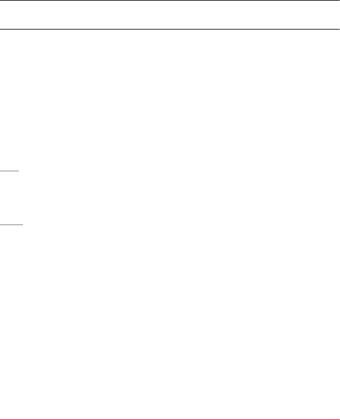
Agile Requirements Designer 3.3
Requirements Insight
For you as Project Owner or Business Analyst it's essential to know how changes to one requirement affect the whole
project. Your Test Data Engineers use the Agile Requirements Designer desktop application to create projects and
versions, model requirements, and save the resulting flow files to a shared repository, the ARD Hub. Your team then uses
the web interface to review requirements in context.
Use the web interface for the following tasks:
•
Use the Projects tab to browse projects and versions from anywhere, simply in your web browser.
•
Use the Flow View tab to review flows. You can even bookmark flows and share the URLs with reviewers.
•
Use the Flow Dependencies tab to gain insight into dependencies between projects, versions, and flows. Drill down
into the relationship graph to analyze the impact of changes on files, versions, and projects.
Log Into the Web Interface
Before you can view flows in the web interface, your system administrator must install and configure ARD Hub and tell you
the server name.
Log In
1. Open the ARD web interface at http://ard_hub_server.yourcompany.com:8080/ard/ui .
2. Enter your Active Directory username and password.
3. Click Log in.
The Welcome page opens. You can view flows, visualize dependencies, and browse projects.
Log out
Click My Account, Log Out to end your session.
The system also logs you out automatically when your session times out.
Manage Flow Projects in the Web Interface
As a Project Owner or Business Analyst, you use a diagramming tool to model requirements for multiple products and
releases as flows. You want to group flows by project and version, so you can review how requirements change over
time. We recommend that you store your models in ARD Hub, a repository that's shared among stakeholders, Test
Engineers, and Testers.
TIP
Each flow that you view in the web interface has a unique persistent URL that you can bookmark in the
browser. Paste these URLs into user stories in your software lifecycle tool so your team members can reference
requirements easily. Or share these URLs with stakeholders who want to quickly open and review flows.
The ARD web interface is a helpful tool to inspect the dependencies between requirements. Here, stakeholders
review flow models in context to surface implicit dependencies in your systems, across projects and versions. Agile
Requirements Designer helps you see the big picture, so you can analyze what impact one change has on different
versions of the project, or on linked projects.
Your team members who edit flows manage projects through ARD Studio. For more information, see Manage Flow
Projects in ARD Hub.
The web interface offers the following functionality:
116

Agile Requirements Designer 3.3
Navigation
Open the ARD Hub web interface and use the quick start buttons on the home page to perform the following tasks:
•
Click Open to view a flow in the repository.
•
Click Manage to manage projects, versions, and flows.
•
Click View to visualize dependencies between projects, versions, and flows.
For information about importing existing flows into ARD Hub, see Migrate Flows Into the ARD Hub.
TIP
When a flow is already open in the desktop application, you can open it quickly in Requirements Insight: In the
ARD Hub connector, right-click the flow, and select View in Browser.
Group Flows by Project and Version
As a Project Owner or Business Analyst, you want to create projects to track requirements for different software
components. You also want to track new versions of requirements for each release of the software component. And
within each Version, you want to group models in folders, for example, to store data flow requirements separate from user
interaction requirements, and so on.
Click Projects in the navigation pane. On the Projects screen, you manage projects and versions, and open flows from
the repository.
Use the Actions menu to manage versions, and folders in your projects:
•
In each project, Project Admins can create, rename, and delete versions.
•
At any level, users can create, rename, move, and delete folders.
•
In each folder, users can rename, move, delete, and lock flows.
Note that after you rename an item, the list refreshes, and the renamed item re-appears in its new position in the list,
which may be below the fold.
TIP
Need a new project? System Administrators have access to User Management and Project Management
screens where they create, delete, or rename projects, and they have access to the Keycloak UI to control user
permissions. For more information, see Manage ARD Hub Users Roles and Projects.
View Requirements and Dependencies
For you as Project Owner or Business Analyst, it's essential to know how changes to one flow affect the whole project.
You can filter flows by Project or by Version, or sort them by their Last Updated dates. From there, you can identify and
open requirements, subflows, and parents.
Click Projects in the navigation pane. Drill down from projects to versions to see individual flows. Click the pagination
links to list more folders in versions, or to list more flows in folders.
The Requirements, Subflows, and Parents columns show you how many dependencies each flow has. Click the colored
icons to open links to direct dependencies.
•
Parents
Displays the list of flows that link this flow as a subflow. The parent flows are affected if you edit this flow in ARD
Studio.
•
Subflows
Displays how many subflows are linked in this flow.
•
Requirements
117

Agile Requirements Designer 3.3
Displays how many application links are defined in this flow. Application links are links to lifecycle tool applications, for
example, used for ALM Requirements Traceability. This column shows which requirements are affected if you edit this
flow in ARD Studio.
Tip: Use ARD Studio to manage Requirements IDs and application links in flow blocks.
View Flow Details
When you click to open a flow in the web interface, the Flow View window opens. You can drag the mouse to move
around the canvas, and use the scroll wheel to zoom in and out.
The Flow View displays the following details in the top left:
•
A breadcrumbs path showing project, version, and parent folders.
Tip: You can navigate quickly by clicking breadcrumb levels.
•
Flow name
The Flow View displays the following details in the top right:
•
Number of parent and subflow (child) dependencies
•
Number of requirements
•
Creator and creation date
•
Last modifier and last modification date
Compare Versions
If a project has more than one version, you can compare what changed between the base version and another selected
version.
1. Go to Projects and identify the project whose versions you want to compare.
2. Click Actions..., Compare Version on the base version folder.
The Compare Versions dialog opens.
3. Select the version to which you want to compare the base version.
The web interface shows you the following differences, if applicable:
–
Flows that are only in the base version
–
Flows that are only in the selected version
–
Modified Flows
–
Renamed Flows
–
Moved Flows
4. (Optional) View more details:
–
Hover the mouse over the Hierarchy icon to view the project path and version of a flow.
–
Click the name of the flow to open it in the web interface.
–
Click the Desktop icon to open the flow in the ARD Studio Desktop application.
Edit Flows
Open the flow in the ARD Studio to edit the model and its properties.
Visualize Flow Dependencies
You as Project Owner or Business Analyst use the Flow Dependencies window in the web interface to see correlations
between several flows in context. This view helps you gain insight into implicit dependencies in your system, which helps
you understand the impact of a change before you edit any model.
118

Agile Requirements Designer 3.3
View Dependencies Within and Between Projects
The visualization is always relative to the focused project and version.
To focus on a single flow and its dependencies, follow these steps:
1. Open the web interface and go to Projects.
2. (Optional) Select a project name and a version to filter the list.
3. Drill down the project tree to a flow.
4. Click Actions, View Flow Dependencies. If the flow has no dependencies, this menu item is unavailable.
The Flow Dependencies window shows you dependencies between this flow and its parents and subflows, if
applicable.
To focus on the dependencies of a specific project, or folder, or version, respectively, follow these steps:
1. Go to Flow Dependencies.
2. Click Select Starting Point.
3. (Optional) Select a project name and a version to filter the list.
4. Drill down and select either a version, a folder, or a flow.
The Flow Dependencies window shows you dependencies between the selected item and related projects and
versions.
If you select a folder or version that does not contain any flows, the visualization pane remains empty.
How do I read the visualization?
The relationship diagram shows all dependencies between focused flows, their parents, and their subflows. Arrows in the
diagram represent parent→child relationships.
Right-click a node and select Include Dependencies to expand the diagram even further. You can inspect dependencies
between multiple projects and versions within the same repository.
119

Agile Requirements Designer 3.3
How to filter projects or versions
If there are external relationships to other versions or other projects, the visualization displays a colored legend. To
include or exclude specific projects or versions from the visualization, select them in the legend. The filtered view updates
dynamically.
Tip: Hover the mouse over a node to see its full name. Hovering over a node also highlights the edges between the
node's direct requirements, which is helpful when reading larger diagrams.
How do I view flow properties in the visualization?
Select a node in the Flow Dependencies visualization to view the following flow properties:
•
Flow name, Project name, Version name
•
Creation time stamp, Created by user
•
Last updated time stamp, Edited by user
•
Dependencies: Number of parents (purple) and Number of subflows (orange)
•
Requirements: Number of linked requirements
Tip: For Relationship or Requirements numbers larger than zero, click the number to open a menu of direct links to the
respective flow.
To view all relationships relative to the selected node and its subflows, right-click the node and select New Visualization
From Flow. To open the selected flow in the Model viewer, right-click the node and select Open Flow. To edit the flow,
use ARD Studio.
Manage ARD Hub Users Roles and Projects
Only the ARD Hub System administrator can create and manage projects, and manage user access to projects.
Control Permissions
As system administrator, you use Keycloak to manage permissions for users and groups. In the Keycloak interface, you
can additionally export and import permission settings as json files.
1. Open a web browser and go to http://hub_server:port/ard/api/iam/auth .
2. Log in as ARD Hub system administrator.
3. Use the menus to manage groups, users, sessions, events, and import or export settings.
User Management Audit Logs
You can find the audit logs for user management at: <ard_home>\data\audit. For example, C:\Users
\Administrator\.ard\data\audit.
Project Management Audit Logs
Any transactional operation performed on projects via the ARD UI or desktop application gets logged in the Audit logs.
In the ARD UI, the audit logs are made available atSystem Administration > Project Management > your project
name > Click the ellipses icon > Audit logs.
120

Agile Requirements Designer 3.3
The following are the transactional operations at the project level that get logged.
Transaction types Transactional Operations
Flows
•
FLOW_RENAMED
•
FLOW_CREATED
•
FLOW_DELETED
•
FLOW_COPIED
•
FLOW_MOVED_FOLDER
•
FLOW_MOVED_VERSION
•
FLOW_MODIFIED
•
LAYER_RENAMED
•
LAYER_CREATED
•
LAYER_DELETED
•
LAYER_COPIED
Folder
•
FOLDER_RENAMED
•
FOLDER_CREATED
•
FOLDER_DELETED
•
FOLDER_COPIED
•
FOLDER_COPIED_VERSION
•
FOLDER_MOVED
Version
•
VERSION_RENAMED
•
VERSION_CREATED
•
VERSION_DELETED
•
VERSION_COPIED
•
VERSION_UPD_REF_SUBFLOWS
Project
•
PROJECT_RENAMED
•
PROJECT_CREATED
•
PROJECT_DELETED
•
PROJECT_COPIED
•
PROJECT_ACCESS_CHANGED
Promote Users to System Administrators (System Role)
You as system administrator can promote other users to a system administrator role. For more information about what a
system administrator can do, see ARD Hub User Roles and Permissions.
Follow these steps:
1. Open a web browser and go to http://hub_server:port/ard/ui .
2. Log in as ARD Hub system administrator.
3. Click System Administration and select the User Management tab.
4. Use the search bar to find specific users.
5. For each user, click Actions, Change System Role, and select Administrator to promote them, or User to demote
them.
Create a Project
Only ARD Hub system administrators can create new projects.
1. Open a web browser and go to http://hub_server:port/ard/ui .
2. Log in as ARD Hub system administrator.
121

Agile Requirements Designer 3.3
3. Click System Administration and select the Project Management tab.
4. Click Projects.
5. Click Actions, Create Project.
6. Enter the following project properties:
–
Project Name
–
Version Name
–
Visibility
Public projects and their contents are visible for all users. Private projects are, by default, hidden from the projects
list; only assigned users can see them and their contents.
7. Click Create.
Assign Multiple Users to a Project
Use this procedure if you want to add multiple users to the same project, or if you want to change roles of multiple users in
the same project.
By default, public projects provide Viewer permissions for all users. For your users to be able to edit newly created
projects, assign users to the project and give them Project Admin or Project Editor roles. Adding users and roles is
especially relevant for private projects because they remain hidden (and uneditable) without explicitly added users.
1. Open a web browser and go to http://hub_server:port/ard/ui .
2. Log in as ARD Hub administrator.
3. Click System Administration and select the Project Management tab.
4. Click Projects.
5. Use the search bar to find the project whose users you want to manage.
6. On the project row, click Actions, Manage Users in Project.
The Manage Users dialog opens.
7. Here you can add users to projects, remove them from projects, or assign them roles:
–
To add users, use the search bar to find existing users that you want to add, and click Assign User. If this is a
private project, they can now see the project and its contents in the project list.
–
To delete users, click Remove Assignment. If this is a private project, removed users can no longer see it or its
contents. If it is a public project, removed users can still view it and its contents, but they cannot edit it.
–
To assign user roles, use the Project Role drop-down to make a user a Viewer, Editor, or Project Admin. For
more information about what each user role can do, see ARD Hub User Roles and Permissions.
8. Click Done.
Assign a User to Multiple Projects
Use this procedure if you want to assign one user to multiple projects, or if you want to change the roles of one user in
multiple projects.
1. Open a web browser and go to http://hub_server:port/ard/ui .
2. Log in as ARD Hub administrator.
3. Click System Administration and select the Project Management tab.
4. Click Users.
5. Use the search bar to find the user whom you want to assign to multiple projects.
6. On the user row, click Actions, Assign/Unassign Projects.
The Manage Projects dialog opens.
7. Here you can assign projects to the user, remove them from projects, or change their project roles:
122

Agile Requirements Designer 3.3
–
To assign projects, use the search bar to find projects, and click Assign Project. If this is a private project, the user
can now see the project and its contents in the project list.
–
To unassign projects, click Remove Assignment. If this is a private project, unassigned users can no longer see it
or its contents. If it is a public project, removed users can still view it and its contents, but they cannot edit it.
–
To change user roles, use the Role drop-down to make this user a Viewer, Editor, or Project Admin for a specific
project. For more information about what each user role can do, see ARD Hub User Roles and Permissions.
8. Click Done.
Hide or Show Projects
Only ARD Hub system administrators can hide projects from the projects list.
1. Open a web browser and go to http://hub_server:port/ard/ui .
2. Log in as ARD Hub system administrator.
3. Click System Administration and select the Project Management tab.
4. Click Projects.
5. Use the search bar to find the project that you want to show or hide.
6. For each project, click Actions, Change Visibility.
–
Public projects and their contents are visible for all users.
–
Private projects are, by default, hidden from the projects list; only assigned users can see them and their contents.
7. Click Save.
Rename Projects
Only ARD Hub system administrators can rename projects.
1. Open a web browser and go to http://hub_server:port/ard/ui .
2. Log in as ARD Hub system administrator.
3. Click System Administration and select the Project Management tab.
4. Click Projects.
5. Use the search bar to find the project that you want to rename.
6. For each project, click Actions, Rename Project.
7. Click Rename.
Delete Projects
Only ARD Hub system administrators can delete projects. The project and its contents are deleted permanently, this
action cannot be undone.
1. Open a web browser and go to http://hub_server:port/ard/ui .
2. Log in as ARD Hub system administrator.
3. Click System Administration and select the Project Management tab.
4. Click Projects.
5. Use the search bar to find the project that you want to delete.
6. For each project, click Actions, Delete Project.
7. Click Delete.
Copy and Paste Assignments
ARD Hub system administrators can copy one project's user assignments and use them as a template to apply to another
project. Similarly, you can also copy one user's project assignments and use them as a template for another user.
1. Open a web browser and go to http://hub_server:port/ard/ui .
123

Agile Requirements Designer 3.3
2. Log in as ARD Hub system administrator.
3. Click System Administration and select the Project Management tab.
4. Click Projects (or Users).
5. Use the search bar to find the project (or user) whose assignments you want to copy, and click Actions, Copy
Assignments.
6. Use the search bar to find the project (or user) where you want to paste the copied assignments, and click Actions,
Paste Assignments.
A dialog displays a summary of changes. New assignments are added. Overlapping assignments are overwritten.
7. Click Yes to apply the changes, or No to cancel.
124

Agile Requirements Designer 3.3
Test Generation
After you have designed your requirements and modeled the application behavior, you want to generate test cases
(paths). A Path of Blocks in a Flow represents a series of test steps in a test case. You use the Path Explorer to view all
combinations of steps that make up your potential test cases (paths).
Use the Path Explorer to generate, view, filter, sort, and store paths. The Path Explorer contains an Optimizer that helps
you identify a minimal set of paths that cover specific test scenarios.
NOTE
In this documentation, we use "path" and "test case" interchangeably: This is because in the case of integrated
software lifecycle tools such as Rally, ALM, and TFS, a test case is nearly always represented as a path
in Agile Requirements Designer. When you use JIRA, you can represent a test case as a block, path, or flow,
respectively.
Path Explorer
There is not one best optimization for all test goals. For a visual explanation of available optimization types, see
Optimization Techniques.
If you consider the content of the Agile Requirements Designer canvas equivalent to a requirements specification,
then Path Explorer collects all test cases into a single venue for displaying them as a test plan. Path Explorer extracts
individual test cases from the complete set of requirements. Use this tool to collect paths in one place and navigate
through them.
Click Manage, Path Explorer to open Path Explorer.
Path Explorer offers the following functionality:
•
Optimize paths through flows for best coverage
•
Filter and sort paths to drill down and find the optimal set
•
Manually create paths by dragging and dropping blocks from the flow into the Path Builder window
•
Store paths or test cases for subsequent actions like Find or Make
•
Export paths or test cases as scripts or files
•
Print paths or test cases
Optimize Flows
There is not one best optimization for all test goals. For a visual explanation of available optimization types for different
requested coverages, see Optimization Techniques.
NOTE
By default, the Legacy Optimizer skips all paths through loops. If you expected more paths to be generated, first
verify whether the flow contains loops, and then verify your loop settings.
Unlike the Legacy Optimizer, the Latest Optimizer analyses the flow and intelligently selects the most
appropriate algorithm to achieve the requested coverage fastest. It's also faster when it generates paths for
flows that contain loops and constraints; you no longer need to define loop settings manually.
Your last used settings persist after you close the Path Explorer window. You have the option to revert to the default
settings.
125

Agile Requirements Designer 3.3
Follow these steps:
1. Select an Optimization type from the drop-down in the Path Explorer window to streamline analyses performed using
the Flow.
Available optimization types are:
–
Full Coverage - All possible Paths
Lists all possible paths. Every possible permutation through the Flow is covered.
In fact, the number of possible paths, including loops, is infinite. In the latest optimizer, all possible paths are
generated as a combination of the DFS and All Pairs algorithms. DFS generates all possible paths that do not
contain the same block three times, which ensures that all paths with loops are included. The All Pairs algorithm
adds the paths needed to cover uncovered pairs of edges.
–
Maximal Coverage - All Edges
Lists the minimum number of paths that ensures that every edge (arrow) is visited at least once.
–
Maximal Coverage - All Nodes
Lists the minimum number of paths that ensures that every node is visited at least once.
–
Full Coverage - All In/Out Edges
Builds the minimum number of test cases such that all pairs of in- and out- arrows are covered by those test cases.
This option is equivalent to the weak functional coverage metric.
–
Full Coverage - All Pairs
Ensures that every pair of decision outputs gets covered. For every emanating arrow from every decision block, all
pairs of arrows from different blocks are covered. This option is excellent for configuration testing.
2. (Optional) Click Load Default Settings to make Path Explorer forget your last used settings. Active non-default
settings are indicated by an exclamation mark icon.
3. Click Optimization Settings.
The Path Construction Settings window opens. Note: The options have different labels depending on whether you
are using the Legacy or Latest Optimizer.
–
(Legacy Optimizer) Advanced Settings: Condense Paths
(Latest Optimizer) Generation: Path Compression – is always set to Approximate and cannot be changed,
but of course optimization can be cancelled in the condensing phase, resulting in partial condensing.
The path condenser obtains a minimum set of paths that still ensures 100% coverage.
•
Disabled — Disable the path condenser to obtain a non-minimal set of paths with 100% coverage. This method
is the fastest.
•
Approximate — Reduce the number of paths while maintaining 100% coverage. This method is slower for large
flows.
•
Optimal — Obtain a minimal set of paths while maintaining 100% coverage. This method is slowest for large
flows.
–
(Legacy Optimizer) Decision Table Settings: Integration Type
(Latest Optimizer) Component Coverage: Decision Table and Subflow Coverage
This option determines how decision tables and subflows are resolved as a secondary optimization target.
Default — If you have selected "all paths", "all pairs", or "all in/out edges" optimization, then "All Rows" is used;
otherwise, "Singular Row" is used.
•
All Rows — Each row in a decision table is applied to the path set in an optimal way, such that each decision row
is covered at least once.
•
Singular Row — It's enough if only one row is selected through the decision table for each path.
•
(Latest Optimizer only) All Row Combinations — All combinations of rows in a decision table are used in paths.
•
(Latest Optimizer only) All Pairs of Rows — It's enough if each pair of rows in a decision table is used at least
once.
•
(Latest Optimizer only) All Rows as Edges — Each Row in the decision table is considered an edge, and the
optimizer settings for All Edges or All Pairs act accordingly.
126

Agile Requirements Designer 3.3
4. Click Loop Settings and define loop insertion options. This setting is only applicable if the flow contains loops, and it
is only available for the Original/Legacy Optimizer.
Enter values larger than zero to generate one or more paths through loops. By default, this option is set to zero and
the optimizer skips all paths through loops. However, the Latest Optimizer does generate paths that go through loops
as many times as necessary, meaning that such paths are needed to meet the coverage target. Typically that happens
with All Pairs, which are always included in All Possible Paths as mentioned above.
5. Click Start Optimization.
The Optimizer lists all paths that match your choices and previews the first path.
6. Click the numbered paths in the list, or use the Showing Path x out of n selectors in the bottom left, to view and
analyze one path after the other.
TIP
To view specific Block Properties, right-click the header of the table view on the right and add and remove
columns.
Filter Paths
Use the From and To drop-down list and select two blocks in the current Flow (typically the Start and End blocks) to list
details regarding the current path interval in the pane on the right.
Use a Filter to display only paths according to filter criteria which you can combine. After filtering, path actions (store,
export, coverage) apply only to the displayed paths. For more information, see Filter Paths.
Sort Paths
Prioritize Test Paths using the Sort By drop-down list at the bottom of the window. You can order tests by Test
Importance (Highest First) or by Path Length (Shortest First).
Store Paths
After you have generated an optimal set of paths for your coverage, you can store them. Continue working with stored
paths as described in the following documents:
•
Store Paths
•
Populate Custom Path Collections
Export Paths
1. Go to the Manage tab and open the Path Explorer.
2. Go to the View Test Cases tab and click Export Paths.
3. (Optional) Configure Settings. For more information, see Configure Dynamic Data Resolution For Export.
4. Choose a target from the drop-down, and click Export.
For more information about exporting and importing paths to specific targets, see Integrations.
Videos
Watch the following videos to learn more about the functionality of the Path Explorer.
Video: An overview of the functionality of the Path Explorer window's Generate Test Cases tab.
Video: An overview of the buttons in the Path Explorer window: Sort Path, Store Path, Print Path, Export Paths, etc.
127

Agile Requirements Designer 3.3
Video: Define a path manually
Optimization Techniques
Running tests for all possible combinations covers all cases, but you cannot afford the time it takes to run them. Your
goal is to identify the minimum number of combinations of nodes (steps) or edges (choices) that cover the cases that are
relevant to the requirements of your stakeholders.
There is not one best optimization for all test goals. Use the Optimization Type drop-down list, at the top of the Path
Explorer window, to streamline the analyzes that you perform using the flow.
128

Agile Requirements Designer 3.3
Full Coverage - All possible Paths
This option lists all possible paths. Every possible permutation through the flow is covered. It is the weakest optimization
and it will always overtest. Use this option to get a baseline and gauge the maximum number of test cases.
Full Coverage - All Pairs of Edges
For every decision in the flow, this option ensures that every pair of decisions gets covered. This means, for every
emanating arrow (edge) from every decision block, all pairs of arrows from other decision blocks are covered. This option
is excellent for configuration testing.
129

Agile Requirements Designer 3.3
Maximal Coverage - All Nodes
Lists the minimum number of paths that ensures that every block (every test step) is visited at least once. Use this option
if you do not need to test all decision outcomes.
Full Coverage - All In/Out Edges
This option builds the minimum number of test cases such that all pairs of in- and out- arrows of each decision are
covered by test cases. This option is equivalent to the weak functional coverage metric.
130

Agile Requirements Designer 3.3
Maximal Coverage - All Edges
This option lists the minimum number of paths that ensures that every edge (arrow) of every decision is visited at least
once. Use this option if you do not need to test all combinations of decisions.
Minimal Coverage - Probabilistic
This option lists paths based on probability statistics. You can generate a specified number of paths with proportional
representation of paths based on their probability (Number Paths). Or you can set a probability threshold: The optimizer
generates only paths whose probability is equal or higher than the specified threshold value. You define the edges that
you want to favor in the Block Properties under Output Details.
131

Agile Requirements Designer 3.3
Advanced Optimization Settings for Edge Cases
In the Path Explorer, click Optimization Settings to open the Path Construction Settings window.
•
Tradeoff
The advanced Tradeoff options handle edge cases where not all paths may be covered.
Typically, you do not need to change any Tradeoff settings.
–
Exhaustive Depth First Search
If you expect to find many more paths than the Optimizer shows, enable this option to use a different search
algorithm that covers certain edge cases better.
–
All Rows Post-Processing Only
If you have flows with subflows and decision tables, and you get the same results in Agile Requirements
Designer 2.9 and 2.10, but 2.10 is noticeably slower, then enable this faster optimization strategy for your case.
•
Alternatives
The alternative setting brings speed advantages if you manually customize the properties for your use case.
–
Default
–
Alt. Constructive Search
A statistical approach to path generation (non-deterministic). Usually it is faster than the Default algorithm, but you
need to tweak parameters to get full coverage.
Store Paths
Before you export paths, you can optimize, filter, name, and store the paths that you most commonly need. You can
categorize paths by types, such as "Test cases" or "Complexity Cases". After you have stored paths, you view or edit
them on the View tab in the Path Explorer.
Store Paths
Before you can view paths, select paths to store.
1. Open a flow and then open the Path Explorer.
132

Agile Requirements Designer 3.3
2. Use the drop-down menu under Stored Path Type to categorize your paths. Default: Test Cases
Subsequently generated paths are stored under the selected category.
3. Click Store Path, Store Selected or Store All.
The Path Name Template dialog opens.
4. Name the path.
For information about automatically naming multiple paths, see Use Templates to Name Multiple Stored Paths.
ATTENTION
Do not use apostrophes or double quotes in path names; special characters may cause integration
problems.
5. Click OK to confirm the path name.
The paths are stored.
Use Template Functions to Name Multiple Stored Paths
When you store multiple paths of different types, you want to be able to identify stored test cases and tell them apart
easily. Use the provided template functions in the Path Template dialog to generate unique path/file names and path
descriptions.
•
Path names typically include relevant chosen outputs, unique numbering, or names of relevant blocks in this path.
•
Path descriptions are typically used when exporting paths to initialize a description field in an integrated lifecycle tool.
The generated path description is also visible as an uneditable field in the Details View in ARD Studio's Path Explorer.
TIP
Use template functions to keep track of mutually exclusive decisions: Insert mutually exclusive Edge template
functions together in the same template, for example, Choose Edge:Red Edge:Yellow Edge:Green .
When generating paths, unused edges generate as empty strings, and only the function for the chosen edge is
initialized with text, which results in, for example, Choose Green .
Template Set
Optionally, give the Template Set a name and click OK. When you name the template set, it is saved with the flow. If you
share a flow with colleagues, named template sets are also available to them.
However, a template set does not require a name. If you leave this field empty, the set is saved in your local ARD instance
for all flows. It is saved as "(unnamed)" in the Template History. When you share the flow, unnamed sets are not included.
Template Set History
The Template Set History button (clock icon) lets you recall recent and saved template sets, including the five most recent
templates from the previous ARD release. If you use a legacy template set, it will be included as a named set in this flow.
•
Click the History button, select a path type, and select a template set to use in this flow.
Tip: Hover over a template set name in the History menu to preview the template in the dialog.
•
Click History, Recent Template Sets to select sets recently used with this flow, as well as legacy sets.
•
Click the X button to delete the current template set from this flow.
Alternatively to using an existing template set, you can create a new template set, as described under Define Path Name
Templates.
Path Name Templates
Providing a Name Template is required when you store a path. Saved path name templates are available for reuse when
you generate path names and path descriptions.
When you use template functions in the file name template, consider that variables can be empty or can have the
same values. To ensure unique file names, include the {Path No} or {Next} template functions to number paths
133

Agile Requirements Designer 3.3
consecutively. If paths are exported with the same file name, ARD appends a number, such as “Path (1)” and so on, to
prevent files from being overwritten.
Path Description Templates
The Path Description template is optional, and its three fields (header, body, footer) are empty by default.
The Path Description template consists of a concatenated header, body, and footer. The fields accept multiple lines.
•
The header and footer are the same for all generated paths. The available templates include path and flow functions.
•
The body field only accepts special block-specific template functions. The name generator iterates over all blocks in
the path and concatenates the name string by repeating the body template.
The body template has a filter button so you can limit which blocks are considered in the description.
•
Include or exclude process or decision blocks, start or end blocks, or sub-blocks (blocks inside a Subflow Block), or
select individual blocks to skip.
•
If a filter is active, the filter button looks pressed.
•
To disable the filter, select all blocks.
Path Description Example
•
Header: This is path {Path No} out of {Paths Total}
•
Body: Decision {Block No} with name {Block Name} and description {Block Description}
selects {Decision Output}
•
Footer: This path ended in state {Last Block}
Generates for example the following path description:
This is path 4 out of 12
Decision 1 with name Choose Day and description Date Stamp selects 2020-01-15
Decision 2 with name Preferred Time and description Time Slot selects 10:00-12:00
Decision 3 with name Choose Location and description Office Name selects Head Office
This path ended in state No appointment available
Define Path Name Templates
A default name template for each path type is always available.
Choose one of the following name template options:
•
Enter a literal path name. Use this option when you are naming only one path.
•
Combine literal text and template functions to name multiple paths. Click a template function in the tree to insert a
naming template into the string.
For a list of all available functions, see Path Naming Template Functions in the reference section.
Example: Test Case {Path No} of {Total No}
•
Create a resolvable expression using the TDoD Service from the Test Data Manager integration (TDM Data Painter).
Choose this option to systematically name test cases based on path data.
a. Click the Edit button next to the Template field.
b. Log on to the TDoD repository. The Select Level window opens.
c. Select a starting level or a saved Flow from the project tree, and click OK. The Data Painter window opens.
d. Define the path name using relevant custom variables, and click OK.
Example: Test case with claim found = ^ClaimFound^ and inquiry type = ^InquiryType^
You return to the Path Name Template window.
e. Enable Resolve Path Name Using Path Data.
134

Agile Requirements Designer 3.3
Refresh Path Names and Descriptions
When you add new blocks after you have defined a filter, return to the filter settings and define filtering for the new block
manually. For example, if your filter is set to include all decision blocks, and you have added a decision block, you need to
include it in the filter manually.
After you have edited a template that is in use, regenerate the names and descriptions of your stored paths:
1. Open the Path Explorer.
2. Go to the View Test Cases tab.
3. Click Recreate Stored Paths' Names and Descriptions.
View Paths by Type
There are five default stored path types that you can use to categorize your paths:
•
Test Cases (default)
•
Use Cases
•
Complexity Cases
•
Backup
•
User Stories
To view paths by type, follow these steps:
1. Click Manage, Manage Stored Path Types.
2. Select a Stored Path Type.
3. Open the Stored Paths tab.
4. Click Show in Path Explorer to return to the View tab in Path Explorer where you can see this path in context.
TIP
Use the Path Collection Editor to populate a whole path type. For more information, see Populate Custom
Path Collections.
Customize Path Types
You can rename or delete existing path types, and add custom path types.
1. Click Manage, Manage Stored Path Types, and click Details.
To manage path types, you have the following options:
–
Click Add path type to add a custom path type.
The Details tab on the right automatically populates itself with the default details of the new path type.
–
Type the new name into the Path Type Name field to rename a path type.
–
Click the Delete icon to delete a path type.
Note: This also deletes all paths stored under this type.
–
Left-click the Path Type Name, enter the new name, and click Save to rename a path type.
2. Configure the default path types that are used when you create paths.
a. Go to File, Configuration, General Config.
b. Change the settings on the Default Path Types tab.
View Cost and Complexity Summary of Stored Paths
Click Manage, Manage Stored Path Types. On the Details tab, you can view a summary of the following path properties:
•
Stored Paths Count
135

Agile Requirements Designer 3.3
The number of paths stored under this type.
•
Current Complexity
The sum of complexity of all paths stored under this type.
•
Current Cost
The sum of cost for all paths stored under this type.
•
Default Complexity
The default level of complexity assigned to each block stored under this path type.
•
Testing Factor
The proportion of testing costs to implementation costs.
•
Blended Rate Per Unit
The overall average cost per hour, per employee.
Find and Remove Duplicate Stored Paths
1. Click Manage, Manage Stored Path Types.
2. Select a Stored Path Type and open the Stored Paths tab.
3. Click Remove duplicate paths. Or click Remove all paths to clear all stored paths.
View Details of Stored Paths
1. Click Manage, Manage Stored Path Types.
2. Select a Stored Path Type and open the Stored Paths tab.
3. Click the Details icon to view properties of the stored path:
–
General: Name, Notes, Blocks Count, State, Importance, etc.
–
Details: Complexity, Make and Find configuration, etc.
–
Settings: Optimization Type, Decision Table Integration, etc.
–
Modification history
–
Runs
–
People and Roles
–
External Links
–
Automation
–
Custom Fields
Rename Stored Paths
1. Click Manage, Manage Stored Path Types.
2. Select a Stored Path Type.
3. Open the Stored Paths tab.
4. Left-click a path name, enter the new name, and click Save.
Analyze the Impact of a Change
If you have stored paths and make changes to the flow, you want to analyse the impact of that change. For larger
changes, and to ensure that the optimization produces the smallest set of tests for the highest coverage, we recommend
to delete all stored paths and re-run the Optimizer on the updated flow.
For minor changes, the Path Impact Analyzer can try to repair affected stored paths by finding a new shortest path.
Follow these steps:
1. Open the Path Explorer and go to the View Test Cases tab.
The Path Impact Analyzer opens and shows a list of affected stored paths.
2. Review the stored paths and read how the latest changes impacted this path.
136

Agile Requirements Designer 3.3
Example: A warning "Missing or modified link between nodes." with suggested repair method "Using shortest path
between them."
3. (Optional) Enable the Reset the path names to default after repair checkbox to refresh the stored paths' names.
Disable the checkbox to keep the old names.
4. (Optional) Press the Export button to export the affected stored paths as a CSV file.
5. Choose how to proceed for one or all affected stored paths:
–
Hide All
Postpones the decision for now, closes the Analyzer window, and returns you to the View Test Cases tab.
–
Move All
Moves all affected stored paths into a Path Type, so you can deal with them later.
Tip: Hide all affected paths to close the window, and create a new Custom Path Type; then return to the View Test
Cases tab to move them all.
–
Delete, Delete All
Removes one or all affected stored paths including their attributes. Use this option if you want to start over because
the Analyzer cannot repair the paths. Then use the Path Explorer to regenerate all paths.
–
Repair, Repair all
Reruns the Optimizer on one or all affected stored paths by finding a new shortest path.
Filter Paths
In the Path Explorer, you can scrutinize individual paths in more detail by stipulating specific path start and end points.
Use the From and To drop-down list and select two blocks in the current Flow (typically the Start and End blocks) to list
details regarding the current path interval in the pane on the right. You can select specific start and end points by using
the drop-down list beneath each point, allowing the isolation of specific sections of the Flow.
Additionally, use the Filter to display only paths according to filter criteria which you can combine. Note that after filtering,
path actions (store, export, coverage) apply only to the displayed paths.
Follow these steps:
1. Click Manage, Path Explorer, and click Optimization Settings.
The Path Construction Settings window opens.
2. Specify your Filter Settings.
Choose one of the following:
–
Inclusive Filtering
Generates all paths, and then displays all paths that touch one of the blocks selected in the filter at least once.
Example: Show all paths that contain an Error block type somewhere.
Block Type: Error
–
Exclusive Filtering
Creates paths that exclusively pass through the blocks that are identified by the filter. Often used with a negation
operator.
Example: Show all paths that are made up exclusively of non-Error block types.
NOT Block Type: Error
NOTE
Exclusive Filtering can result in zero paths being displayed if your filter is too restrictive. For example, if
you filter exclusively for Decision blocks, but you have no paths that are made up of nothing but Decisions
blocks, then Exclusive Filtering displays no results.
3. Click Apply to return to the Path Explorer.
4. Click Filters to specify filter criteria.
The Filters window opens.
137

Agile Requirements Designer 3.3
5. Create a filter expression, or select a previously Stored Filter from the list.
a. Select a Filter Type and click Add.
•
Application — Filters by presence of a link to a lifecycle tool integration or exporter/importer
•
Automation Defined — Filters by presence of configuration
•
Test Data Defined — Filters by presence of configuration
•
Has Expected Results — Filters by presence of configuration
•
Find System Data Defined — Filters by presence of configuration, see also Make and Find Data
•
Make System Data Defined — Filters by presence of configuration, see also Make and Find Data
•
Test Data Variable — Filters blocks with a specific variable assigned
•
Automation Snippet — Filters blocks with a specific code snippet assigned
•
Specific Item — Filters a specific block or edge
•
Decision Output — Filters a specific output
•
Block Run Status — Filters a specific run status (passed, skipped, failed)
•
Block Status — Filters a specific status (Defined, In-Progress, Completed, etc.)
•
Stored Path State — Filters a specific path state (Defined, In-Progress, In-Testing, Completed, Blocked, etc.)
•
Stored Paths — Filters a specific path
•
Subflow Reference — Filters a specific subflow
•
Clones — Filters clones or masters
•
Duplicates — Filters duplicates or masters
•
Symbol Type — Filters Start/End blocks, Subflow blocks, Process blocks, Decision blocks
•
Assert Type — Filters by expected result assertion
•
Error Type — Filters by expected result error
•
Plain Text — Filters blocks that contain a given free-form string
•
Image — Filters blocks that have an image file attached
•
Pins — Filters by pin color combinations, see also Use Pins to Highlight Paths or Items
•
Block Type — Filters by optional block property
•
Observability — Filters by optional block property
•
People and Roles — Filters by optional block property
•
Requirement IDs — Filters by optional block property
•
Test Importance — Filters by optional block property
•
Virtualized End Point — Filters by optional block property
b. Provide necessary parameter values to the filter.
c. (Optional) Insert Boolean operators and add more Filter types to create complex filters.
d. Verify that the expression editor indicates "Valid Expression".
6. (Optional) Click Store Filters to store a filter for future use.
7. Click Apply Filters to, or click Clear Filters to start over.
When you apply a filter, only the paths where all the nodes meet the filter criteria are displayed.
Populate Custom Path Collections
You use the Path Collection Editor to populate custom path collections, for example to distinguish "Automated Test Cases"
and "Manual Test Cases". Agile Requirements Designer comes with several predefined collections by default:
•
Test Cases
•
Use Cases
•
Complexity Cases
•
Backup
•
User Stories
138

Agile Requirements Designer 3.3
When you store paths, you can rename, delete, and create path collections. The Path Collection Editor lets you populate
path collections with the intersection, union, or differences of two existing path collections.
Example
You have defined the following paths types:
•
[Automated Test Cases]
•
[Manual Test Cases]
You have already generated test cases in both path types, and you are running these test cases for every release.
Now you want to create two new Path Collections:
•
[Manual Test Cases to consider removing]
•
[All test cases]
After you have created them, these two collections are empty. You want to populate them using the Path Collection Editor:
•
To get a list of manual test cases to consider removing:
a. You decide to store the result in the empty collection "[Manual Test Cases to consider removing]".
b. You apply the following operation to populate the list:
[Automated Test Cases] INTERSECTION [Manual Test Cases]
c. The [Manual Test Cases to consider removing] collection now contains only test cases that are in [Automated Test
Cases] and also in [Manual Test Cases].
•
To get a list containing all test cases:
a. You decide to store the result in the empty collection "[All test cases]".
b. You apply the following operation to populate the list:
[Automated Test Cases] UNION [Manual Test Cases]
c. The [All test cases] collection now contains all test cases that are either in [Automated Test Cases] or in [Manual
Test Cases], or in both.
Populate Path Collections
1. Open a flow.
2. Click Manage, Path Settings, Path Collection Editor.
3. Click Manage Stored Path Types to create an empty path collection.
a. Click Add Path Type.
b. Define a name on the Details tab.
c. Click Save.
You created the empty target collection that you want to populate.
4. Select the empty target collection from the Store Result drop-down.
5. Build a valid expression to populate the target collection:
a. Insert the first Path Collection.
b. Insert one of the following operators:
•
Union
•
Intersection
•
Difference
c. Insert the second Path Collection.
Example: To populate the collection with all test cases from two existing collections, use the union
operator. [Automated Test Cases] UNION [Manual Test Cases]
6. (Optional) To build more complex expressions, use the left and right arrows to move the caret, and
insert parentheses to group expressions.
139

Agile Requirements Designer 3.3
Example: [Automated Test Cases] INTERSECTION ( [Manual Test Cases Old] UNION [Manual
Test Cases New] )
7. Verify that the expression is valid.
8. Click Apply Operation.
Agile Requirements Designer displays the result:
–
Success - the following unique paths were found
The result is stored in the target collection.
–
Failed to find any new paths from the proposed query
The target collection remains unchanged.
Risk-Based Test Case Generation
Risk-based test case generation allows you to get a set of test cases based on the probability of the occurrence of certain
paths. If you know how probable it is that each test case (path) occurs in real life, you can import this data into Agile
Requirements Designer, and filter out the least probable test cases that do not need to be tested.
Define Path Probability
Before you start a risk-based analysis, you must supply the data which determine the probability of each path.
There are two ways to provide probability data:
Define the Output Probability
Manually enter a probability value how often each output of each decision block is likely to occur.
Follow these steps:
1. Open each decision block.
2. Go to the Output Details tab.
3. Select each output under Display Output.
4. For each output, enter the percentage in the Enter Output Probability field.
Calculate Probabilities From Spreadsheet
Import a CSV file containing a set of test cases. The spreadsheet must contain the following columns: test case number,
block name, block description, output.
The probability (optional column) of a decision table row is the likelihood of that event occurring. This is then used in
generation of paths. In general, the higher the likelihood of a row occurring the more frequently it will appear in the paths.
Optimize Paths
The Path Explorer enables you to get the right set of paths based on path occurrence probability.
1. From the Optimization drop-down list, select Minimal Coverage - Probabilistic. Click Run.
The the Probability Optimiser window opens.
2. Select the preferred optimization type:
Probability Type:
–
Number Paths
Defines how many paths (test cases) to generate. Paths are proportionally represented based on probability. For
example, if you create 100 paths, for a path that has 20% probability, 20 test cases will be generated. This option
is good for generating data and performance testing, simulating the most probable (frequent) user interaction, and
generating data with specific distribution.
–
Probability Threshold and Operation
140

Agile Requirements Designer 3.3
Generates only paths whose probability is equal or higher (Operation) than the set threshold. For example, the
value of 0.2 means that only paths with probability equal or higher than 20% will be generated. This option is
suitable when you want to test only the most probable paths.
3. Select whether you want to calculate probability from manual statistics or from imported data.
4. Click Compute.
Analyze Stored Paths
You can review probability statistics for your stored paths. By applying probability data, you get the most likely scenarios
to occur in your test model.
To start analyzing your stored paths, view your stored test cases in the Path Explorer, and click Path
Statistics (calculator icon).
In the Path Statistics window, you have the following options:
•
Settings
Allows you to calculate probability for paths with or without Constraints applied.
•
Get Probabilities from Manual Statistics
Probability statistics is based on the values manually entered for each decision block output.
•
Get Probabilities from Data
Probability statistics is based on the data from an imported CSV file.
•
Run Status
Displays statistics according to test case run status (failed, passed or not run).
•
The table at the bottom of the window shows details for all decisions outputs of all blocks present in the stored paths.
•
You can add path traffic to see the distribution of traffic through your flow.
•
The Cumulative Path Probability and Cumulative Path Traffic fields display the sum probability and sum traffic of all
stored paths.
Log Test Case Results
You can log the results of executed test cases within Path Explorer. In this way, Agile Requirements Designer assists in
uniting requirements-planning, test case planning, and test case design, which streamlines the entire testing process.
Follow these steps:
1. Save a path and switch to the View tab.
2. Click Run Selected to log the results of an executed test case.
The Run Stored Path dialogue appears.
3. Highlight the relevant row and click the respective button to mark each stage as Skipped, Passed or Failed.
Agile Requirements Designer automatically jumps to the next row.
4. Click Save Run to save the assigned states.
After you have updated the state of each stage, the Overall Path State is displayed. If at least one state is "Failed", the
Overall Path State is marked as "Failed".
To gain a bird’s-eye view of the status of all test cases, view the Path Properties in the right side of Stored Paths within
Path Explorer, and click the Runs tab. A summary log of each run is displayed.
Each path stores its run information separately so there is no overlap or confusion. To obtain details about each run,
double-click individual entries. You cannot edit the run at this stage in order to preserve the traceability or audit trail.
141

Agile Requirements Designer 3.3
Managing Test Data
Using Agile Requirements Designer, you can connect to a TDM Datamaker repository and use it to create or find test
data based upon custom data sets. The primary benefit is that you can use Data Painter's seed lists—provided files with
generic sample data sorted by domains, such as first names, last names, cities, and so on. This Test Data simplifies live
tests, while still implementing a richer set of test data.
For more information about TDM integration, see the Test Data Manager documentation.
Test Data Example Scenario
1. Browse to the Examples folder under the default Agile Requirements Designer installation pathway.
2. Open the example file LegBeforeWicket.vtf.
3. Click Test Factory, Test Data to open the Test Data dialog.
The screenshot shows the test data that has been associated with the Flow LegBeforeWicket.vtf.
The columns reflect the fields created under their related blocks within the Flow.
A closer look at one column’s data expressions gives a better indicator as to how these functions are created. In the
Batter column, the application is requesting a random entry to be returned from a seed list of Batter’s names. The “0”
refers to the expected number of nulls to be returned – in this case, zero: no blank cells are to be left.
Click Resolve to open a new tab and see the data expression resolved into actual players’ names. All of these names
were randomly retrieved from their respective seed lists – “Batter”, “Bowler” – and inserted back into the appropriate
column upon the “Resolve” command.
Filter Visible Test Data
If you are viewing large flows with subflows, or with many test data variables, you may want to inspect only a relevant
fraction of your test data when exporting paths.
1. Click Test Factory, Test Data to open the Test Data dialog.
2. Click Test Filter Options to show and hide variable columns in the Test Data window:
142

Agile Requirements Designer 3.3
–
Use the search box to find variables to hide or show.
–
Enable the checkboxes for variable columns that you want to hide.
–
Disable the checkboxes for variable columns that you want to show.
Associate Test Data with Blocks
To use the Test Data feature, you assign data expression to blocks.
1. Double-click a block to open its Properties window.
2. Go to the Test Data tab and click Add variable...
3. Fill in Name, Description, Type, and default Value. Click OK.
The variable data appears as a new row.
4. Do one of the following steps to assign data:
–
Click Edit Native Value to define a static value.
–
Click Edit Resolvable Value in Data Painter to enter a data expression.
5. Click Save.
Data Painter
You use the Data Painter to construct data expressions, for example expressions based on functions that extract data
from provided seed lists. Other data manipulation functions are also available such as inserting certain characters or
strings, replacing characters or strings, the rounding-off of numbers to a configurable number of decimal places, or even
the padding or capping of strings.
Follow these steps:
1. Double-click a block to open its Properties window.
2. Go to the Test Data tab.
3. Click Edit Resolvable Value in Data Painter for one of the variables that you just added.
4. Log on to your TDM Repository if prompted.
Available functions are listed in the leftmost pane. Available variables are listed in the center pane. Available columns are
listed in the rightmost pane.
If you want to use a function already implemented for a different column:
1. Select the function from the list of Functions. A separate pane opens where you can choose a seed list. Click OK to
insert this entire data expression into the topmost section of the pane.
2. Define the percentage of nulls that you wish to retain by specifying a value for the highlighted “percnull” placeholder.
This can be any value from 0 to 100.
If no nulls are desired, enter “0”.
3. Click OK at the bottom-right of this pane to preserve this expression. This will return you to the Test Data tab of the
block.
4. Click Save.
5. Click Test Factory, Test Data to open the Test Data dialog.
6. Click Resolve.
The new tab that appears display a fully resolved list of data.
Edit Expressions in the Data Painter
Click the Gear button to toggle between the old and new Data Painter windows. In the new view, you see the data
expression in two panels: a classic display on the left-hand side, and on the right-hand side, a hierarchical tree which
provides better readability of complex expressions. You can revert to the old view at any time.
143

Agile Requirements Designer 3.3
•
Edit the expression in either panel, and click Create Tree from Expression or Create Expression from Tree to
propagate the changes to the other panel.
•
For more comfort, you can edit a subexpression in a separate window. Select a subnode in the tree and click the Edit
selected subexpression button.
•
The Highlight sub-expression button highlights the part of the expression that corresponds to the selected node in
the tree.
•
To resolve the whole expression, click the Resolve selected value or Resolve selected subtree buttons below the
left-hand pane or any selected functions or arguments in the tree in the right-hand pane.
•
Use the Check for Errors button to validate the data expression in both the expression panel and the tree.
Make and Find Data
Find and Make is the ability to find data which is interesting to you (data attributes that match your Flow), and if you
cannot find them, you can generate the matching data.
The Find and Make functionality uses the Test Data Manager (TDM) Datamaker integration. You can assign functions to a
process or decision block in a flow. When a certain step is completed in the Flow, it triggers the Find or Make process.
Set Up Make Data
Follow these steps:
1. Go to the Connectors and connect to your TDM Repository.
2. Open a flow, edit a block, and go to the Make System Data tab.
3. Click Set Publish.
4. A pop-up window displays a project tree from within Datamaker to select the level to publish the data.
5. Select a relevant data pool (data pools are marked by
the icon)
from the project tree.
All of the associated variables available are displayed in the right pane.
6. Click the check-box on the relevant row to select the required variable.
The focus switches to the Value field of the chosen row, allowing you to edit the associated value. Alternatively,
double-click any of the entries in the Value column to edit the value associated with the variable.
7. Click OK to confirm the selection and return to the Attributes pane.
8. Repeat this process for all arrows associated with a decision or process block.
Note: After you have added the required values, the data pool from which they were selected appears as an entry in
the “Datamaker publish” display box, while the variables selected appear in the “Publish Variables” display box.
9. Click Save to commit these changes and incorporate these values into the Flow for use in Path Explorer.
If you want to undo your changes and start again, click Reset to clear all values.
Set Up Find Data
The process for mining existing test data from across multiple back-end systems (Test Matching) is similar to that
described for Make Data.
Follow these steps:
1. Go to the Connectors and connect to your TDM Repository.
2. Open a flow, edit a block, and go to the Find System Data tab.
3. Click Set test match to display the Datamaker project tree.
4. Browse to the project.
144

Agile Requirements Designer 3.3
In the project tree,
the icon
marks a data pool containing test criteria which need to be matched with appropriate data.
5. Select the data pool.
The data pool displays a list of available test criteria.
6. Click the check boxes next to each criterion to select them.
Tip: You can also add custom criteria by clicking the Add Custom Criteria button.
7. Repeat this process for all arrows associated with each decision or process block.
If you want to undo your changes and start again, click Reset to clear all values.
Execute Find and Make
Each process block has Find and Make data properties, and every Decision block has Find and Make properties for each
output.
Make Data
Follow these steps:
1. Open Path Explorer and switch to the stored paths view.
2. Click Make Data to submit a publish job for each publish level in the path using the variables just set.
3. In the Default Publishes dialog that appears, you can execute the following operations:
–
Schedule the publish job
–
Set the number of repeats desired
–
Email the published data to users
–
Specify a thread of the batch engine
–
Set the preferences of actions to perform if the publish job is a duplicate
4. Click OK to open the Profiles window.
5. Select the target and source to which to publish.
After the publish job has completed, a confirmation dialog box appears. If you have chosen to have these results emailed
to a valid account, you receive a .zip attachment containing a summary of the publish job along with an error log, if any
errors were generated.
Find Data
Unlike Make Data, the Find Data process submits a test data mining (Test Matching) job for every path registered in the
data pool, and not simply the currently opened path. Aside from this, the processes are similar to perform.
1. Click the Find Data button.
2. The Test Match Options dialogue appears.
3. Schedule the start of this process (extremely useful on high-load, high-throughput systems).
4. Enter an email address to receive the data directly, or select alternative threads.
Make and Find Data at Test Execution Time
As a Test Data Engineer, you use Test Data Manager (TDM) to generate test data, and you export test cases from Agile
Requirements Designer to HPE ALM for your Testers. You have specific test data associated with each test case. You
created ARD flow blocks that trigger a custom Make and Find Data process in the TDM Portal to generate the data.
145

Agile Requirements Designer 3.3
By default, TDM Portal generates this test data when the test engineer exports the test cases to ALM. If your Testers,
however, have a requirement to use live data, you can configure the integration to create test data when the tester
executes the test cases in ALM, as described in this scenario.
The Tester customizes the Execute button in the HPE ALM web interface to submit publish jobs to the TDM Portal. This
publish job now uses the test data criteria file at test execution time.
Requirements
•
Connect Agile Requirements Designer to your TDM Repository.
For more information, see Managing Test Data and Manage Flows in the TDM Repository.
•
Configure your HPE ALM integration and connect Agile Requirements Designer to your HPE ALM server.
For more information, see Integration With Lifecycle Tools.
•
Customize the Execute button in the HPE ALM web interface to run a VB script that submits publish jobs to the TDM
Portal.
For more information, search for Customize HP ALM in the Test Data Manager documentation.
•
Prepare two flows (see ../../../../../../assets/docops/tco/ard-alm-integration-sample.zip):
–
A TDoD flow that defines the data criteria and variables to generate data using Find and Make.
Example: Full Data Criteria.vtf
–
A functional flow that defines the test cases that use the data. One path in the functional flow corresponds to one
test case in ALM.
Example: Promotion Scheme.vtf
For more information how to define publish variables, see Make and Find Data.
Include TDM Test Data Criteria on Export
As Test Data Engineer, want to include test data criteria in each export, so Testers can generate live data at test execution
time in TDM.
1. Click Home, General Config.
The Configuration window opens.
2. Click Connectors Options, and open the HP Application Lifecycle Management section.
3. Enter your credentials and click Login.
The Configuration window lists your HPE ALM connector options.
4. Enable the Include TDM Test Data Criteria on Export option. By default, this option is disabled.
5. Click Save.
You have configured the ALM exporter to include a test data criteria file.
Export Test Cases to ALM
As Test Data Engineer, you export test cases and test data criteria for the Testers.
1. Click Connectors and connect to your TDM Repository.
2. Click Connectors and connect to HPE ALM.
3. Open the functional flow.
4. Open the Path Explorer, generate paths and store them.
5. Go to the View Test Cases tab and click Export Paths.
6. Select HP Application Lifecycle Management and click Export.
The Export Paths windows opens and displays your ALM folder structure to the left and test cases to the right.
7. Select an existing target folder or create a target folder.
8. Click OK.
A dialog asks you to select the TDoD flow to define a TDM test data criteria file.
146

Agile Requirements Designer 3.3
9. Click Yes.
The Select a TDOD Flow window opens.
10. Browse the project tree or use the search box to select the TDoD flow for the functional flow. Click OK.
The test cases and their test data criteria are exported to ALM.
(Optional) Verify Export
As Test Data Engineer, you may want to verify that the test data criteria file is attached to the test case in ALM.
1. Open HPE ALM and log in.
2. Go to Testing, and select the target folder.
The folder contains the exported test cases.
3. Open a test case.
4. Verify that test case contains Design Steps and an Attachment "AGDLINKS ".
The attachment is the test data criteria file for this test case.
5. Open the test data criteria file in a text editor.
6. Verify that the test data criteria file contains
–
the TDoD flow context, and
–
publish variables.
Generate Data for Test Cases
As Tester, you have the requirement to generate live test data right before you execute test cases in ALM. At this point it's
assumed that you have configured ALM to work with TDM to generate test data.
1. Customise ALM to trigger Test Data makes in TDM Portal. For more information, see Customize HP ALM in the TDM
documentation.
Ypu have added a button to your ALM web interface.
2. Open HPE ALM and log in.
3. Go to Testing, and select the target folder.
The folder contains the exported test cases.
4. Open a test case and click the button that you have enabled in step 1.
ALM executes the configured VB script and opens the TDM portal in the browser.
You use TDM Portal to generate test data.
1. Log in to TDM Portal.
The TDM portal displays data criteria fields.
Note: The values from the test data criteria file are prefilled and you cannot change them.
2. Define your criteria, select a Data Pool, and click Next.
3. Define FIND values, select a Data Pool, and click Next.
4. Define Publish criteria, select a Data Pool, and click Next.
5. Enter your ALM credentials and click Sign in.
6. Enter your email address to receive notifications, and choose a schedule time.
7. Click Request.
The TDM Portal indicates that the publish request was created.
Wait for the request to complete. The TDM portal creates the datapool as a test mart. Next, the TDM Portal sends the test
data back to ALM as an attachment.
1. Return to the ALM interface.
2. Click Refresh.
3. Go to Testing, and select the target folder.
4. Open a test case.
147

Agile Requirements Designer 3.3
5. Verify that there is an attachment TEST_123_GTDATA.csv that contains the test data for this test case.
Repeat this procedure to generate live data for each test case.
Use Test Data Manager Actions in ARD
Instead of you having to open Test Data Manager, you can use the Datamaker connectors directly in Agile Requirements
Designer. When prompted, connect to a Test Data Manager connection profile. For more information, see the Test Data
Manager documentation.
Open the Connectors Dock, right-click a data pool, and choose one of the following actions:
•
View Pool Details
•
Edit Data—If no data is defined in this data pool, you can either create data manually, or select tables and
use Accelerators to create data. If you have TDoD service version 4.2.0.2 or higher, you can specify if the data is a
Stored Column.
•
TDM: Data Definition for datapoolname —Displays the Data Definition using the integrated TDM engine. Use
this action to review variables, functions, and relationships quickly.
•
TDM: Row 1 Data Definition for datapoolname —Displays the Data Definition of the first row using the integrated
TDM engine.
•
TDM: Stored Columns for datapoolname —Opens the Stored Columns window where you can select which
columns you want to store.
Open the Connectors Dock, right-click a data group, data set, or data pool, and choose one of the following actions:
•
Use as Context—Defines the context against which all variable values are resolved, for example, custom Test Data
Manager variables inside your Agile Requirements Designer flow. The current context is displayed either below or
above the canvas.”
Note: DataMaker variables such as RANDLOV or SEQLOV are not supported here. If you use an EXECSQL, it must
return only one value.
•
TDM: Delete name—Deletes this level.
•
TDM: Find and Replace in name
•
TDM: Upgrade name—Upgrades inherited file objects available in different project versions. For more information, see
"Upgrade Inherited File Objects" in the Test Data Manager documentation.
Click DataBuilder, Launch TDM to access TDM actions. Depending on context, this menu also contains data pool
actions.
•
Project Manager
•
Register Tables
•
Actions for Registered Objects
•
Reconcile Tables
•
Maintain Object tags
•
Maintain Seed Data
•
Data Source SQL Window
•
Data Target SQL Window
The TDM actions launch Datamaker and open the respective window in the provided context.
148

Agile Requirements Designer 3.3
Integrations
ARD offers integration with many Broadcom/CA and third-party testing tools to leverage model-based testing across your
whole testing toolchain.
Agile Requirements Designer integrations cover the following use cases:
•
Import flows or basic information that is defined in commonly used generic flow charting or basic tools (such as
Microsoft Visio, rich text files, and Microsoft Excel files) into Agile Requirements Designer flows.
•
De-duplicate large imported flows.
•
Export optimized flows back out to generic formats as needed for collaboration.
•
Import test suites from common testing tools into Agile Requirements Designer flows.
•
Import test cases from common lifecycle management tools such as HPE ALM into Agile Requirements Designer
flows, optimize the test cases, and export them back into their lifecycle tools
•
Integrate with lifecycle management tools to attach models and test cases directly to relevant stories.
•
Define the Application Link property of a block to link a block to an item inside an external application such as HPE
ALM, Rally, Microsoft TFS, or Atlassian Jira.
Supported integrations
Model Imports
•
BPMN
•
XPDL
•
Visio (VSDX)
•
Existing test case deduplication
Model Exports
•
Image
•
XPDL
•
BPMN
•
Visio
•
XML
•
PDF
•
SVG
•
CSV
•
Excel
Two-Way REST connectors
Two-way connectors import and export test cases from and to external tools.
•
Rally
•
HPE ALM
•
Atlassian Jira
•
Microsoft Team Foundation Server
•
qTest
149

Agile Requirements Designer 3.3
File-based Test Case and Model Imports
•
Excel
–
Step-based test cases
–
Data-driven test cases
•
XML
File-Based Test Case Exports
•
Excel (customizable)
•
XML
Coverage Report Exports
•
Excel
Configuration importers
•
JSON/XML Request/Response pairs.
Automation Exports - Tool-based
•
BlazeMeter GUI Functional Tests
•
Critical Logic TMX
•
Test Data Manager (TDM) - Javelin
•
Application Test
Automation Exports - Script File-based
You can configure ARD for any language. Multiple language layers are possible.
•
Any scripting language
–
Selenium, Protractor, UFT
–
Mobile languages like EggPlant and Perfecto.
–
Including in-house languages
•
Any keyword-based language
–
Including in-house languages (via configuration).
•
Any data-driven setup, for any tabular or flat file format
–
For custom data driven setups
–
For tools like UFT or Application Test (DevTest Solutions)
•
Accelerators for frameworks
–
Ranorex
–
EggPlant (for Mobile)
Packaged App tools
•
TurnKey
Test Data Management
•
Direct connection to TDM for back-end data creation and mining
•
Synthetic data creation per test case via TDM
•
Test data criteria export via Excel
150

Agile Requirements Designer 3.3
Other Integrations
•
Service Visualization: Agile Requirements Designer generates Request/Response pairs for each test.
Service Virtualization
The following video shows how to export request/response pairs to Service Virtualization to aid in the creation of data-
driven virtual services:
Atlassian JIRA
The following video shows how to export optimized test cases from Agile Requirements Designer to Atlassian Jira:
JUnit
The following video shows how you can bulk import run results from JUnit into Agile Requirements Designer:
HPE ALM - Roundtrip
The following video shows how to import test cases from HPE ALM, optimize them, and export them back to HPE ALM:
HPE ALM - Link to data
The following video shows how to link optimized test cases to data in HPE ALM:
Using Plugin Framework
The plugin framework helps you to connect to the target application. It also helps you manage flows by letting you perform
operations, such as creating, updating, and deleting flows from the target application.
A Developer's guide and Reference guide for the ARD Plugin Framework can be downloaded here.
The following sections describe how you can use the Plugin Framework.
Connect to the plugin server
To connect to the plugin server:
1. In ARD Studio, Under the connectors pane, click Plugin Framework.
The Connectors Dock pane appears on the right-hand side.
2. Enter the URL and click Show Available Plugins.
The Plugins drop-down box will show all the available plugins.
3. From the drop-down box, select the desired plugin. For example, Zephyr.
4. As part of authentication, enter the username and password. If you have selected Zephyr, it will ask you for URL and
API Token. The authentication formats will change as per the selected plugin authentication requirements.
5. Click Log In.
Configure mapping
To configure mapping for the plugin framework.
151

Agile Requirements Designer 3.3
NOTE
The mapping for the plugin depends upon the plugin you are connected to.
1. In ARD, go to General Config > Plugin Framework.
A list of Levels and projects underneath appears.
2. Select the project for which mapping is to be done. For each entity available under the project, each attribute can be
mapped to an ARD attribute.
3. Map the available Attribute Name column fields with AgileDesigner Selected Mapped Attribute.
–
If you want to export the block, you can map the attributes present under the Block tab to a corresponding ARD
attribute.
–
If you want to export the path, you can map the attributes present under the Path tab to a corresponding ARD
attribute.
–
If you want to export a flow, you can map the attributes present under the Flow tab to a corresponding ARD
attribute.
4. Click Save & Close.
Disconnect from the plugin server
Once you are connected to the plugin server, you get a Log Out button under the Connector Dock pane. You can click
this button to disconnect from the plugin server.
Create a Path
To create a path.
1. Go to Export > Connectors.
2. In the Export window, select the Plugin Framework.
3. Select the Path Type.
4. Click Export.
5. In the Export to Plugin Framework window, select the target level.
6. If you are exporting it for the first time, the default action available is Create.
7. Click OK.
Update a Path
To update a path.
1. Go to Export > Connectors.
2. In the Export window, select the Plugin Framework.
3. Select the Path Type.
4. Click Export.
5. In the Export to Plugin Framework window, select the target level to update.
6. Paths which can be updated does have the Update action automatically selected.
7. Click OK.
Delete a Path
To delete a path.
1. Go to Export > Connectors.
2. In the Export window, select the Plugin Framework.
3. Select the Path Type.
4. Click Export.
152

Agile Requirements Designer 3.3
5. In the Export to Plugin Framework window, select the target level.
6. Under the Action column, select Delete.
7. Click OK.
Optionally, you can use the Delete removed paths checkbox to delete a path, which was previously deleted in ARD, from
the target application.
Configure Dynamic Data Resolution For Export
After you have created the test model and generated relevant paths, you want to export your test scripts. You can use
Test Factory, Export Automation to export automation scripts to a version controlled folder; or you may want to export
scripts to a software lifecycle tool and attach scripts to test cases.
When exporting, Agile Requirements Designer resolves generated data, such as random user names. Before release
2.7, generated test data was resolved every time you exported, this means, that the generated data in two exported sets
of scripts could differ. From release 2.7 on, you can choose whether you want to cache resolved test data, or force the
exporter to resolve it every time.
Every time you export, you can set the resolution behavior as needed. For more information on how to specify the default
behavior globally, see Enable Standard Settings and Advanced Features.
Follow these steps:
1. Open a flow.
2. In the Path Explorer, open the View tab.
3. Click Export Paths.
The Exporter dialog opens.
4. Expand the Settings and configure the following:
–
Export current type / Export current type range from n - m
Specifies that, by default, all of the current type is exported. Alternatively, you can restrict the export to a range.
–
Force data resolution
Specifies whether to cache resolved test data, so that dynamic values persist for subsequent exports. Enable this
option to force the exporter to resolve generated data every time, without caching.
5. Choose an export target.
For detailed information about individual export targets, see the Integrations section.
–
XML
–
Automation
–
Service Virtualization, Application Test, Rally, Nolio Release Automation
–
HPE ALM, Atlassian Jira, MS TFS, Tricentis qTest
6. Click Export.
Import and Export Visual Flows
You can initialize flows based on existing data, for example diagrams or XML files. You also can export flows for further
processing, for example in a spreadsheet format or as an image.
NOTE
Verify that you have a valid installation of Test Data Manager (TDM), Microsoft Excel, Microsoft Visio, Adobe
Acrobat, and so on, in order to import from or export to respective proprietary formats.
Export Flows to External Formats
You can export Flows to a variety of supported formats:
153

Agile Requirements Designer 3.3
•
Image: PNG, BMP, JPG
•
A generalized spreadsheet exporter based on custom Excel templates (XLSX)
•
Microsoft Excel (XLSX)
•
Comma-separated values (CSV)
•
Extensible Markup Language (XML)
•
Adobe Acrobat (PDF)
•
Microsoft Visio diagrams, Microsoft Word (Office 2013)
•
HPE QC, HPE ALM
•
Oracle BPMN
•
XPDL
To export Flows, click Export in the Ribbon menu, select the desired format. The Export menu also includes
a Print option.
Import External Formats to Agile Requirements Designer
You can create Flows by importing data from existing documents. Agile Requirements Designer supports the
following formats:
•
General Test Cases Importer: XML, CSV, and Excel formats
•
Rich Text
•
Microsoft Visio diagrams (VSDX)
•
HPE QC, HPE ALM
•
Web Service Call Importer (enable under Advanced Features)
•
Request Response Importer
•
Datamaker Publish Process (Test Data Manager integration)
•
Datamaker Table (Test Data Manager integration)
•
Application Test (DevTest Solutions)
•
DataVis (CSV)
•
Selenium Builder (Automatic Model Building Accelerator)
•
Parasoft SOATest
•
Smartbear SoapUI (Beta)
•
Oracle BPMN
•
XPDL
•
TIBCO Nimbus
Follow these steps:
1. Click File, New.
2. Title the new flow. You can use the same name as the source file. Click Finish.
3. Click Import in the Toolbox Dock.
4. Choose the file type to import, for example, Visio.
5. Browse to the file you want to import, for example a Visio file with .vsdx suffix.
6. Click Open.
The file is imported into the flow.
You can now edit the flow. For more information about editing flows, see Requirements Modeling.
Video: Import from Excel
The following video shows how to import test cases from an Excel spreadsheet:
154

Agile Requirements Designer 3.3
Export to Word
You can export all Stored Paths of a Agile Requirements Designer flow as Microsoft Word document. Alternatively, if you
want to customize the export by providing a custom Word template, see Export to Word Using Templates.
Apply Requirement IDs to each block if your business process requires them. Requirement IDs also make Word exports
more comprehensive, especially when you are preparing a Requirements document.
Define Requirement IDs For A Flow
1. Click Manage, Properties.
2. Open the Requirements IDs tab.
3. Click Add to generate Requirements IDs and add them.
–
Insert a number and click Add to generate sequential numeric IDs.
–
Insert a string and click Add to generate text IDs with sequential numbers as suffix, for example, "Test 1, Test 2,
Test 3".
4. To remove an ID, left-click to highlight the entry and click Remove Selected Entry.
5. Click Save.
Apply Requirement IDs to Blocks
1. Double-click a block to open the properties dialog.
2. Go to the Requirement ID tab of the block.
This tab contains the Requirements IDs previously set up within the overall Flow.
3. Select one or more ID for this block.
4. Repeat this process for all blocks on the canvas, as necessary.
Export the Flow to MS Word
1. Click Export, Document Builder.
2. In the Document Builder dialog, select the items that you want to include in the export.
3. Agile Requirements Designer asks for a save location for the new MS Word document.
MS Word opens and you can observe the document being populated with the selected data.
The exported document includes such features as a General Summary, Detailed requirements and all details of all Stored
Paths.
Export to Word Using Templates
You can export all Stored Paths of a Agile Requirements Designer flow as Microsoft Word document. You can customize
which properties are included by defining a Word template. Microsoft Word 2010 or newer is required. Alternatively, to
export the flow without having to define a template, see Export to Word.
150
Create a Word Template
First, create a Word template that outlines your desired output. An example template file is attached to this
documentation.
You can use the following tags in the template:
•
$text(…)$
Inserts a property as a string of text.
155

Agile Requirements Designer 3.3
Example: $text(author)$
You can export the following flow properties as text:
–
$text(alm)$
–
$text(audit)$
–
$text(author)$
–
$text(description)$
–
$text(diagram_title)$
–
$text(documentation)$
–
$text(environment)$
–
$text(general_requirements)$
–
$text(jira)$
–
$text(no_connections)$
–
$text(no_decision_blocks)$
–
$text(no_process_blocks)$
–
$text(no_requirement_ids)$
–
$text(now)$
–
$text(short_name)$
–
$text(source_code)$
–
$text(test_plan)$
–
$text(version)$
•
$image(…)$
Inserts the flow as an image.
Example: $image(diagram_image)$
–
$image(diagram_image[height,width])$
(Optional) Specify the dimensions of the flow image in square brackets. Provide width or height, or both, in pixels.
Default: If no parameters are specified, the image is rendered the size of the source image.
Examples:
•
$image(diagram_image[100,100])$
•
$image(diagram_image[250,a])$
Sets the width to 250 pixels and scales the height proportionally.
•
$image(diagram_image[a,250])$
Sets the height to 250 pixels and scales the height proportionally.
•
$table(…)$
Inserts a single or multiple tables of properties. Define the column headers of the table in square brackets. The
columns appear in the order in which you have specified them.
You can export the following flow properties:
–
people - names, emails
$table(people[names,emails])$
–
revision_details – author, details, version, timestamp
$table(revision_details[authors,details, version, timestamp])$
–
roles – names, people_assigned
$table(roles[names, people_assigned])$
–
stored_paths – step number, block, expected result, complexity
$table(stored_paths[test_id,test_name,test_state,step_no,block,expected_result,complexity])$
Examples:
–
$table(people[names,emails])$
–
$table(roles[Names,people_assigned])$
156

Agile Requirements Designer 3.3
Export a Flow to Word Using a Template
1. Click Export, Document Builder.
The Document Builder window opens.
2. Enable the Use templates option.
3. Click the folder icon to select your template file.
4. Click Export.
5. Agile Requirements Designer asks for a save location for the new Word document. Click Save.
Word opens and you can observe the document being populated with the selected data.
Export to Excel Using Templates
Use the General Excel Exporter to export flows and stored path elements into a user-defined format, according to
a custom template. The template is an XLSX file which contains keywords corresponding to elements within Agile
Requirements Designer.
Keywords are presented by elements between dollar symbols, for example, $no_nodes$ corresponds to the number
of nodes in the flow. There are also keywords to include General Project Attributes, Diagram Attributes, Stored Path
Attributes, and Requirement IDs Attributes, and more. As the template is processed, the keywords are replaced with the
appropriate values from the exported flow.
When you use the General excel Exporter to export test cases, use the flow- and path-level keywords to access field
values. The block-level keywords To make the most of templates, combine multiple keywords to achieve the desired
report.
This article covers the following topics:
Example
You can create an export template that generates a project overview: The overview states the name of the project, include
flow details such as the number of nodes, decisions, and connections, and includes a table of the project components.
Create the Template
First prepare a template.
Tip: If you want to export a default spreadsheet without having to create a template, use the Excel button from the Export
tab instead.
Follow these steps:
1. Open a blank Excel spreadsheet.
2. Lay out your report by inserting the keywords from the reference below. You can use multiple keywords in the same
cell.
Example:
Project name: $name$
Report date: $now$
Requirement IDs: $requirement_id$
3. Save the spreadsheet and remember its location.
157

Agile Requirements Designer 3.3
Generate the Spreadsheet
When the template is ready, you can use it to generate the report.
Follow these steps:
1. Open a flow.
2. Go to the Export tab and select General Excel.
The General Excel Exporter dialog opens.
3. Define the export options:
–
Output Location
Browse for the path where to save the generated report and define a name for the output file.
–
Template Location
Browse for the location of the template that you just created using the keywords that are listed above.
–
Flow and Path Images
If your template includes the $image$, $path_image$, or $virtualized_path_image$ keyword, choose whether to
generated flow and path images to be included in the exported report.
Note: Generating path images takes additional processing time. The more blocks and paths the flow contains, the
longer it will take to generate the report.
4. Click the Generate Spreadsheet button
The file is populated and saved to the specified location.
Excel Template Keyword Reference
Project Attributes
Keyword Description
$name$ Name of the project
$now$ Time and date of report creation
Stored Path Attributes
The stored path attributes can be further split into two types along with the general attributes:
•
General attributes – attributes that describe the Flow at the top level.
•
Attributes related to the collection of stored paths
•
Attributes related to virtualized paths
General Flow Attributes
Keyword Description
$virtualized_no_paths$ Number of virtualized paths
$no_paths$ Number of paths (inc. virtualized paths)
Stored Path Attributes
Keyword Description
$linked_requirements$ A list of Requirement IDs for the blocks in the stored path.
$path_block_id$ A list of the path block id’s for each stored path
$path_block$ A list of the path block names for each stored path
$path_test_criteria$ A list of the test criteria data for each block in the stored path
158

Agile Requirements Designer 3.3
$path_make$ A list of the make data for each block in the stored path
$path_find$ A list of the find data for each block in the stored path
$path_test_data$ A list of the test data for each block in the stored path
$path_variable$ A list of the variable attribute for each block in the stored path
$path_importance$ A list of the importance attribute for each block in the stored path
$path_observable$ A list of the observable attribute for each block in the stored path
$path_sensitivity$ A list of the sensitivity attribute for each block in the stored path
$path_uses_prod_data$ A list of the uses production data attribute for each block in the
stored path
$path_data_direction$ A list of the data direction attribute for each block in the stored
path
$path_virtualized$ A list of the virtualized attribute for each block in the stored path
$path_end_point$ A list of the end point attribute for each block in the stored path
$path_operation$ A list of the operation attribute for each block in the stored path
$path_block_type$ A list of the block type attributes for each block in the stored path
$path_description$ A list of the description attribute for each block in the stored path
$path_notes$ The notes for each block in the stored path
$path_global_notes$ The notes for each stored path
$path_expected_results$ A list of the expected results for each block in the stored path
$path_environment$ A list of the environment attribute for each block in the stored path
$path_document$ A list of the document attribute for each block in the stored path
$path_source_code$ A list of the source code attribute for each block in the stored path
$path_test_plan$ A list of the test plan attribute for each block in the stored path
$path_audit$ A list of the audit attribute for each block in the stored path
$path_alm$ A list of the HPE ALM attribute for each block in the stored path
$path_jira$ A list of the Jira attribute for each block in the stored path
$path_requirements_details$ A list of the requirement descriptions for each block in the stored
path
$path_complexity$ A list of the complexity attribute for each block in the stored path
$path_name$ A list of the stored path names
$path_image$ An image of each of the stored paths
$path_id$ A list of the stored path IDs
$path_condensed_desc$ A list of short descriptions for each stored path
$path_no_steps$ A list of the number of steps for each stored path
$path_step_id$ A list of the step id’s for each stored path
$stored_path_custom_field['']$ A list of custom attribute values for each stored path. Reference
the column you want to export within the square brackets. The ID
in single quotes is the name of the Stored Path Customer Field.
For example, $stored_path_custom_field['ALM Type']$
$test_data_field['']$ A list of test data for the indicated field for each stored path.
Reference the data field you want to export within the square
brackets.
$path_block_custom_field['.*']$ A list of custom fields that allow you to reference a block custom
field when listing test cases in spreadsheet format
159

Agile Requirements Designer 3.3
Virtualized Path Attributes
Keyword Description
$virtualized_path_block$ A list of the path block names for each virtualized stored path
$virtualized_path_criteria$ A list of the test criteria data for each block in the virtualized stored
path
$virtualed_path_make$ A list of the make data for each block in the virtualized stored path
$virtualized_path_find$ A list of the find data for each block in the virtualized stored path
$virtualized_path_test_data$ A list of the test data for each block in the virtualized stored path
$virtualized_path_variable$ A list of the variable attribute for each block in the virtualized
stored path
$virtualized_path_importance$ A list of the importance attribute for each block in the virtualized
stored path
$virtualized_path_observable$ A list of the observable attribute for each block in the virtualized
stored path
$virtualized_path_sensitivity$ A list of the sensitivity attribute for each block in the virtualized
stored path
$virtualized_path_uses_prod_data$ A list of the uses production data attribute for each block in the
virtualized stored path
$virtualized_path_direction$ A list of the data direction attribute for each block in the virtualized
stored path
$virtualized_path_virtualized$ A list of the virtualized attribute for each block in the virtualized
stored path
$virtualized_path_end_point$ A list of the end point attribute for each block in the virtualized
stored path
$virtualized_operation$ A list of the operation attribute for each block in the virtualized
stored path
$virtualized_block_type$ A list of the block type attributes for each block in the virtualized
stored path
$virtualzed_description$ A list of the description attribute for each block in the virtualized
stored path
$virtualized_nodes$ A list of the notes attribute for each block in the virtualized stored
path
$virtualized_expected_results$ A list of the expected results for each block in the virtualized
stored path
$virtualized_environment$ A list of the environment attribute for each block in the virtualized
stored path
$virtualized_documentation$ A list of the document attribute for each block in the virtualized
stored path
$virtualized_path_source$ A list of the source code attribute for each block in the virtualized
stored path
$virtualized_path_test_Plan$ A list of the test plan attribute for each block in the virtualized
stored path
$virtualized_path_audit$ A list of the audit attribute for each block in the virtualized stored
path
$virtualized_path_alm$ A list of the HPE ALM attribute for each block in the virtualized
stored path
160

Agile Requirements Designer 3.3
$virtualized_path_jira$ A list of the Jira attribute for each block in the virtualized stored
path
$virtualized_path_requirement_details$ A list of the requirement details for each block in the virtualized
stored path
$virtualized_path_complexity$ A list of the complexity attribute for each block in the virtualized
stored path
$virtualized_path_name$ A list of the virtualized stored path names
$virtualized_path_image$ An image of each of the virtualized stored paths
$virtualized_path_id$ A list of the virtualized stored path IDs
Requirement IDs Attributes
Keyword Description
$associated_requirement_ids$ A list of the requirement IDs associated to the current process
$requirement_id$ A list of all the requirement IDs present in the flow
$requirement_description$ A list of all requirement descriptions
Diagram Attributes
Diagram attributes may be further split into four group types, along with the general attributes:
•
General attributes – attributes that describe the Flow at the top level.
•
Decision attributes – attributes just for decision blocks.
•
Process attributes – attributes just for process blocks.
•
Block attributes – attributes for both decision and process blocks.
•
Connection attributes – attributes for the Flow arrows (connectors).
General Attributes
Keyword Description
$image$ Image of the diagram
$no_nodes$ Number of nodes in the diagram
$no_decisions$ Number of decisions in the diagram
$no_connections$ Number of connections in the diagram
$version_custom_field['']$ A list of custom attribute values for each version. Reference the
column you want to export within the square brackets.
Block Attributes
The output lists are sorted by Block ID, that is, in order of Block creation, not by occurrence in the path.
Keyword Description
$block_name$ A list of the block names in the diagram
$block_description$ A list of the block descriptions in the diagram
$block_observability$ A list of the observability attribute values for the each block
$block_complexity$ A list of the block complexity attribute values for the each block
$block_type$ A list of the block type attribute values for the each block
161

Agile Requirements Designer 3.3
$block_importance$ A list of the importance attribute values for the each block
$block_sensitivity$ A list of the sensitivity attribute values for the each block
$block_custom_field['']$ A list of custom attribute values for each block. Reference the
column you want to export within the square brackets.
Decision Attributes
The output lists are sorted by Block ID, that is, in order of Block creation, not by occurrence in the path.
Keyword Description
$decision_name$ A list of the decision block names in the diagram
$decision_description$ A list of the decision block descriptions for each decision block
$decision_complexity$ A list of the decision complexity attribute values for each decision
block
$decision_block_type$ A list of the decision block type attribute values for each decision
block
$decision_observability$ A list of the decision block observability attribute values for each
decision block
$decision_test_importance$ A list of the decision block importance attribute values for each
decision block
$decision_sensitivity$ A list of the decision block sensitivity attribute values for each
decision block
$attribute_output$ A list of the decision block attribute output values for the current
decision block
$attribute_value$ A list of the decision block attribute value values for the current
decision block
$attribute_description$ A list of the decision block attribute description values for the
current decision block
$attribute_criteria$ A list of the decision block attribute criteria values for the current
decision block
$attribute_probability$ A list of the decision block attribute probability values for the
current decision block
Process Attributes
The output lists are sorted by Block ID, that is, in order of Block creation, not by occurrence in the path.
Keyword Description
$process_name$ A list of the process block names in the diagram
$process_description$ A list of the process block descriptions in the diagram
$process_observability$ A list of the process block observability attribute values for the
each block
$process_complexity$ A list of the process block complexity attribute values for the each
block
$process_block_type$ A list of the process block type attribute values for the each block
$process_test_importance$ A list of the process block importance attribute values for the each
block
162

Agile Requirements Designer 3.3
$process_sensitivity$ A list of the process block sensitivity attribute values for the each
block
$process_true_desc$ A list of the process block true description attribute values for the
each block
$process_false_desc$ A list of the process block false description attribute values for the
each block
$process_probability$ A list of the process block probability attribute values for the each
block
Connection Attributes
Keyword Description
$connection_source$ A list of the source connection block name for each connection
$connection_target$ A list of the target connection block names for each connection
$connection_value$ A list of the connection value for each connection
Export to Service Virtualization
Service Virtualization lets you virtualize software service behavior and model a virtual service to stand in for the actual
service during development and testing. Agile Requirements Designer lets you quickly generate rich data for Service
Virtualization. A service or message can be modeled as a flow, with a corresponding configuration file that sets out the
code snippets. The snippets are then compiled by the Path Explorer, creating a set of data which covers every possible
combination of requests and responses.
You can import requests and responses in JSON or XML formats and automatically decompose them into a rudimentary
flow and a configuration file. Replace the values in the requests and responses with variables, find or make data and push
the request/response pairs generated in Agile Requirements Designer to Service Virtualization (DevTest Solutions). The
creation of a new virtual service can also be triggered from within Agile Requirements Designer.
You can push request/response pairs and deploy a virtual service from Agile Requirements Designer using the Service
Virtualization connector. Service Virtualization expects the file suffixes -req.txt and -rsp.txt , respectively.
Follow these steps:
1. Click Home, Automation.
2. Go to the Objects & Actions and Variables tabs. Create request and response automation layers with corresponding
snippets.
For more information, see Import and Export XML or JSON.
3. In the flow, assign the required requests and responses to all relevant blocks. Go to the each block's Automation tab
and add the corresponding automations: Typically, you put the request into a process block, and you assign the
responses to each of the outputs of a following decision block.
4. Go to the Export tab, select your R/R layer, and go to the Export Details tab.
a. Select Separate Scripts.
b. Select a File Naming System that generates unique file names. For example, select Path Number.
c. Define a File Prefix of your choice, for example myService .
d. Define a File Extension of either -req.txt or -rsp.txt , respectively.
You have configured Agile Requirements Designer to generate automation files with unique names, like for
example myService-0-req.txt, myService-0-rsp.txt , myService-1-req.txt , and myService-1-
rsp.txt .
Now you can generate R/R pairs and export them to Service Virtualization.
163

Agile Requirements Designer 3.3
Follow these steps:
1. Click Manage, Path Explorer, generate and save your paths.
2. In the stored path view, go to the Automation tab and review the requests and responses for each path (test case).
3. Click Export Paths and select Service Virtualization.
4. In the dialog, enter the IP address of the CA SV REST API, and the user name and password.
Tip: The REST API typically runs on port 1505 on the machine where the Virtualize Registry is running.
Example: http://registry_ip_address:1505 (Replace registry_ip_address with the actual IP address.)
5. Map the appropriate layer to the Request option in the dropdown, and the other appropriate layer to the Response
option in the dropdown.
6. (Optional) Give the service a name under which it run.
Default: AutoGenService-GUID
7. (Optional) Configure the advanced options:
1.
–
Group
The group tag that the created service is labeled with.
–
Class
The fully qualified class to be used as the transport protocol handler when importing request/response pairs.
–
Base Path
The base path to deploy the created service to.
–
Listen Port
The port that the virtual service listens on.
–
Binary
If checked, the R/R pair import treats the transactions as containing binary data.
–
SSL
If checked, the virtual service listens using SSL.
–
Keystore File
The keystore file that the virtual service uses to provide its certificate when SSL is enabled.
–
Keystore PW
The password of the keystore file that the virtual service uses when SSL is enabled.
–
Separate Bind
If checked, a separate binding phase is needed.
2. Agile Requirements Designer notifies you when the service export is completed and provides the URL on which the
virtual service is running.
More Information:
The following video demonstrates how to use Agile Requirements Designer to generate request/response pairs and
populate Service Virtualization.
Import Rich Text
Agile Requirements Designer is able to import descriptions from a number of different formats, including rich text
documents. The Rich Text Importer is especially helpful when you draft extensive stories, construct requirements, or
compile requirements documentation.
Each line of text becomes the name and (identical description) of a new block in the flow. If you have already decided on
the names of the blocks you want to build, it's faster to type blocks directly into the importer as lines of text, than to create
each block manually.
Follow these steps:
1. Draft your flow in a text file by writing one line of text for each block.
164

Agile Requirements Designer 3.3
2. Go to the Import tab within Toolbox dock in Agile Requirements Designer, and click the Rich Text button.
3. Copy and paste your content into the Blocks Description Text tab of the Rich Text Importer. Agile Requirements
Designer automatically parses the text into different, relevant block formats.
4. Review how the blocks are currently being parsed by looking at the preview on the right hand side of the
importer. Note: The preview is recalculated every time when you modify the text and stop for more than a second.
5. (Optional) Adjust the parsing result manually, if necessary:
–
Start a new line of text to create a block. By default, Agile Requirements Designer creates process blocks.
–
Start a line with the word 'if', or end the line with a question mark ('?'), to create a decision block.
–
Edit properties of parsed blocks manually by clicking the drop down-menus on each cell.
Tip: To apply a change to multiple blocks, hold the shift or control key and click to select multiple rows before
editing a property.
•
Import Action: To Process, To Decision, To Visual Flow Description, To Global Variable, Ignore
•
Block Type: Infrastructure, Data, User Interaction, Error, Code Action, Service Call, Assert
–
Adjust the segmentation of blocks manually.
a.
•
Merge blocks which have been erroneously split by clicking Merge Selected.
•
Split blocks which have been erroneously merged by adding a line break in the parser window.
6. (Optional) Provide values for each line in the Expected Results / Variable Values tab. The values align with the
Blocks Description Text lines.
The Importer populates the expected results in the Process Details of the generated blocks.
7. Configure the import.
–
Limit the name of blocks to this number of characters
(Optional) Defines after how many letters to truncate the name of blocks. The description retains the full line without
truncation. The value is stored as your preference for the next time when you use the importer.
Default: 35 characters
Maximum: 1000 characters
–
Add Connections
Specifies whether you want to import the blocks into the flow as a connected series of sequential blocks, or as
individual orphans.
8. Click OK to convert the parsed text into blocks and place them on the canvas.
TIP
On the canvas, you can make additional adjustments to the Flows. Click Tools, Re-Layout Diagram to lay out
the generated diagram automatically.
Example
You can find an example document (ImportTextExample.docx) in the Examples folder in the Agile Requirements
Designer installation directory. To test the import feature, copy portions of this example document, and paste the contents
into the left-hand pane.
Import From Excel or CSV
The General Importer lets you import test cases from a spreadsheet to Agile Requirements Designer.
Import Requirements
You can bulk import an Excel spreadsheet or CSV file of requirements into a flow. You can use MS Excel (xls/xlsx) or any
text editor (csv) to create the file.
First, prepare the input file.
1. Create a spreadsheet with two columns. Name the column headers "Name" and "Description".
165

Agile Requirements Designer 3.3
Note: The Requirements Importer ignores any other columns.
2. Enter one requirement per row.
Important: Enclose the requirement in quotation marks if the string contains spaces.
3. (CSV only) Ensure that there are no extra spaces around the commas.
4. Save the file in CSV or XLS/XLSX format.
Now you can import these requirements into a flow.
1. Open Agile Requirements Designer and open a flow.
2. Click File, Properties.
The Flow Properties open.
3. Click the Requirement IDs tab and click Import.
4. Browse to the CSV file and click Open.
The requirement IDs and descriptions are imported into the flow.
Examples:
Text file:
Name,Description
A-1.1,"open file"
A-1.2,"save file"
A-1.3,"edit file"
Excel file:
A B
1 Name Description
2 A-1.1 "open file"
3 A-1.2 "save file"
4 A-1.3 "edit file"
Import Test Cases as Paths
Use the General Importer to import test cases from a spreadsheet to Agile Requirements Designer as paths.
Follow these steps:
1. Prepare a CSV file or XLSX file with test case definitions. The file must at minimum define the Path Name and (block)
Name attributes.
Example: You create a spreadsheet with three comma-separated columns for test case name, step description,
and value.
2. Go to Import and select General Test Cases.
3. Open the file containing the test cases that you want to import.
4. Map the spreadsheet columns to Agile Requirements Designer attributes.
Example:
–
Map the 'test case name' column to the Path Name attribute.
–
Map the 'step description' column to the Name attribute.
–
(Optional) Map the 'value' column to the Output Value attribute.
5. When prompted by the Start and End dialog, respond Yes. Agile Requirements Designer creates paths containing
connected blocks with the given output values. Each imported path is created with a Start block.
6. Go to the Test Factory menu and select Re-layout Diagram, and click Update.
166

Agile Requirements Designer 3.3
Example:
test case name step description value
Path1 Have Water TRUE
Path1 Have Tea TRUE
Path1 Want Milk TRUE
Path1 Have Milk TRUE
Path1 Want Sugar TRUE
Path1 Have Sugar TRUE
Path1 Make Tea
Path2 Have Water TRUE
Path2 Have Tea TRUE
Path2 Want Milk TRUE
Path2 Have Milk TRUE
Path2 Want Sugar TRUE
Path2 Have Sugar FALSE
Path2 Do Not Make Tea
Import and Export XML or JSON
You can import files in XML or JSON format to Agile Requirements Designer to create a flow and a configuration. You can
create separate automation layers for requests and responses, and import request and response code snippets to these
layers. You can then export these automation layers to multiple XML or JSON files representing request/response pairs.
Agile Requirements Designer helps you leverage a model of a particular method to create the request/response pairs
to simulate web service behavior.
Importing JSON is almost the same process as for XML, the only difference is that you don't get attributes (such as
<xmltag attributes=””/> for XML), and the import only operates on the underlying data tags.
Example Video: Create Request/Response Pairs
The following video, among other topics, explains how to create and use request-response pairs in Agile Requirements
Designer. The Creating Request/Response Pairs chapter starts at 18:46.
Import XML
When you import a file, you decide how the content will be chunked, which elements are imported as process or decision
blocks, and which values and attributes are turned into variables. The original values from the imported file are preserved
and stored in the automation layer as values of the newly created variables.
Follow these steps:
1. In the Tools Dock, click Import, and drag and drop XML Import on the canvas.
2. Browse for an XML file to import and click Open.
The XML Importer dialog appears and displays the hierarchical structure of the XML file.
3. Specify XML elements that you to import as processes by double-clicking the value in the Process column and setting
it to True. The XML envelope is selected by default, you may want to import the header as a process too.
4. Parameterize all necessary attributes and values. Right-click on an element and select the appropriate option.
Parameterized attributes and values appear in red and they are imported as variables.
167

Agile Requirements Designer 3.3
5. Add the new code snippets (representing the XML elements) to an existing automation configuration layer, or create a
new layer.
Export XML
To export an XML file, use the automation script exporter. Before you start to export, you have to ensure that every stored
path can produce a valid XML file. Verify that the flow begins with a block containing the opening XML envelope tag, a
header, and the file body, and that is has a block with the closing envelope tag at the end.
Import Automation Scripts (Ranorex, Eggplant)
You use the repository connector to import objects from external repositories to Agile Requirements Designer. Currently,
the supported frameworks are Ranorex and Eggplant.
Follow these steps:
1. Open a flow.
2. Go to Connectors, Automation.
3. From the Framework drop-down list, select an automation script type:
–
Ranorex
–
EggPlant
4. Browse for the repository file that you want to import.
The tree view lists all the objects from the repository.
5. Drag and drop the objects that you want to import onto the canvas.
You can use this connector also as an accelerator when modeling your automation. For more information, see Drag and
Drop Automation Steps Onto the Canvas.
Integrate With BlazeMeter
ARD now has access to its own automation execution engine, BlazeMeter.com, an end-to-end testing platform for web
applications
With the addition of BlazeMeter Automation, ARD now has access to its own automation execution engine.
BlazeMeter.com is an end-to-end testing platform for web applications. You generate automation scripts in ARD and
export them to BlazeMeter, where you can run test cases and view reports. For more information, read this blog by
automation expert Marta Benach to see an example of Using Model-Based Testing to Generate BlazeMeter GUI
Functional Tests.
BlazeMeter users who are familiar with the editor for Scriptless GUI Functional Tests will recognize the user interface. For
more information about GUI Functional Testing in BlazeMeter, see Creating a Scriptless Functional Test in the BlazeMeter
Guide.
The BlazeMeter integration has three parts:
1. Connect ARD Studio to a BlazeMeter account and understand BlazeMeter concepts (this article)
2. Link a flow to a BlazeMeter workspace
3. Add BlazeMeter automation to blocks and export test cases to the execution engine
The following video gives you an overview of the workflow and supported features of the integration.
Requirements
1. Register a BlazeMeter account (free or enterprise).
2. Install the free BlazeMeter Recorder Extension in your Chrome browser.
168

Agile Requirements Designer 3.3
3. Use the recorder on your web application under test.
The extension adds objects to the Test Action Library in your BlazeMeter Workspace, so ARD can load them.
Connect ARD Studio to BlazeMeter
The BlazeMeter integration is a top-level tab in Agile Requirements Designer, and not found in the Connectors tab with
the other integrations.
1. In ARD Studio, go to the BlazeMeter tab.
2. Click Log In. The BlazeMeter Logon pane opens.
3. (Optional) If you have enabled Log in Automatically, you can click Forget password if you wish to remove previously
stored credentials from ARD.
4. Enter your BlazeMeter API Key ID and API Key Secret.
5. If you don't have an API key yet, generate one now:
a. Click Generate API keys.
The BlazeMeter Logon window opens.
b. Authenticate with your BlazeMeter account. BlazeMeter generates the keys and ARD prefills the required fields.
6. (Optional) Enable Log in Automatically to store your API Key and Secret in ARD.
7. Click Login.
Now you are ready to enable the BlazeMeter integration in flows and add BlazeMeter Automation to blocks.
Troubleshoot Connection Issues
If you get an error message in the login panel stating that API Key generation has failed, generate the key and secret
manually through the BlazeMeter web interface:
1. Below the error message, click Go To User API Keys Page. You are forwarded to BlazeMeter.com in your browser.
2. If you are not logged in already, authenticate with your BlazeMeter account. You are forwarded to the Settings,
Personal, API Keys page.
3. Click Create a New API key.
a. Enter a name and an expiry date of your choice.
b. Click Generate.
c. Important: Copy the API Key ID and API Key Secret and store them securely.
d. Close the API key window.
4. Return to ARD and enter the API Key ID and API Key Secret into the login panel.
5. Click Login.
Tip: Experienced BlazeMeter users can manage their API keys in the BlazeMeter web interface on the Settings, Personal,
API Keys page.
Understand BlazeMeter Concepts
As an ARD user who wants to make the most of the BlazeMeter integration, you need to know the following BlazeMeter
concepts and workflows.
•
Objects are UI elements in your web application under test, such as buttons, menu items, or input fields. You create
Objects in BlazeMeter by recording them with the BlazeMeter Chrome Extension, the Object Picker, or by manually
entering a locator.
169

Agile Requirements Designer 3.3
You store and edit Objects in the BlazeMeter Test Action Library. You cannot create or edit Objects in ARD Studio, but
you can use them.
•
Actions are standard test actions such as clicking, selecting, or typing. The list is fixed and reflects the actions
supported by the Selenium framework. In each step of a Scriptless Scenario, you apply an Action to a value or Object:
You click a button, you select a menu item, you type a password into a field, and so on.
Note: Currently, the ARD interface supports all BlazeMeter actions except for the control structures (if-else, for, for-
each), which can only be inserted in the BlazeMeter web interface.
•
Groups are custom sequences of Actions that are applied to Objects. You create Groups for common reusable
procedures, such as logging on to the application with a tester account, or navigating to a specific window, and so on.
The advantage is that you update a Group once, and the change is reflected everywhere the group has been reused.
You create and edit Groups in the Scriptless Scenario Editor in BlazeMeter. You cannot create or edit Groups in ARD
Studio, but you can use them.
Configure BlazeMeter Integration
You need to configure Flows before you can use the BlazeMeter integration. We call this step linking a Flow to
a BlazeMeter Workspace.
To use the BlazeMeter integration in Agile Requirements Designer, you need to record and load Objects and Groups from
an existing BlazeMeter Workspace into the ARD Flow.
Workflow Overview
In the typical workflow for the BlazeMeter integration, you first record Objects in BlazeMeter.
1. Open the Chrome browser and log in to your BlazeMeter.com Account and Workspace.
2. Use the BlazeMeter Chrome Extension to record Objects (such as input fields, menus, and buttons) in your web
application under test.
3. (Optional) Edit Objects and Groups in BlazeMeter's Test Action Library.
Example: Create Groups for test steps that you want to reuse across many tests, such as logging in.
Link a Flow to a BlazeMeter Workspace
When your Objects are ready, connect ARD Studio to BlazeMeter:
1. Open ARD Studio and open an ARD flow to which you want to add BlazeMeter automation.
2. Go to the BlazeMeter tab, click Log In, and provide your BlazeMeter credentials.
3. Select the BlazeMeter Account and Workspace whose Test Action Library contains the relevant Objects and Groups.
4. Click Link Workspace.
ARD loads Objects and Groups from the selected Workspace and links them to the Flow.
5. Define your BlazeMeter Automation.
Add BlazeMeter Automation to blocks, export the paths to BlazeMeter, and run the test cases in BlazeMeter.
6. Click Log Out to disconnect the BlazeMeter integration while keeping linked Object and Group references intact.
Unlink a Flow From BlazeMeter Workspace
You can click the Unlink Workspace button to separate an ARD Flow from its BlazeMeter Workspace. If the Flow has
BlazeMeter automation defined, ARD unloads all Objects and Groups that are used in action steps. This means:
•
After unlinking, existing Object and Group references in test steps will be broken.
•
If you link the Flow back to the same Workspace without saving, the Object and Group references are restored.
•
If you link the Flow to another Workspace, ARD loads this Workspace's set of Objects and Groups, and you have to
redefine all broken Object and Group references manually.
170

Agile Requirements Designer 3.3
WARNING
After you have started using Objects and Groups from one Workspace in automation steps, you cannot unlink
and change the Workspace without breaking the scenario.
Integrate with SAP Solution Manager
To support Solution Manager, ARD includes a horizontal Swim Lane block in the toolbox under Other Shapes.
IMPORTANT
The SAP Solution Manager (Solman) integration is a beta feature. To use it, click Settings, go to the Beta
Features tab, and enable SAP Solution Manager integration.
Solution Manager BPMN diagrams can contain Swim Lanes to represent separate processes and roles. To support
Solution Manager, ARD includes a horizontal Swim Lane block in the toolbox under Other Shapes.
Swim Lane blocks in ARD are a purely visual background object with no semantic meaning for path generation.
This integration offers the following functionalities:
•
Connect to a Solution Manager server.
•
Import BPMN files with Swim Lanes into ARD.
The imported flows display Swim Lanes as a background object.
•
Export BPMN flows from ARD to import them into Solution manager.
•
Connect to a Solution Manager server to import flows.
Connect to Solution Manager
First you need to establish an API Connection from ARD to the Solution Manager server.
1. Open the Connectors Dock and click Solution Manager.
2. The Connectors dock shows the Solution Manager login screen.
a. Enter your Solution Manager server URL.
b. Enter the Username.
c. Enter the Client ID.
d. Enter the Password.
e. Click Login. The Solution Manager Connectors dock displays the content tree.
Create Flows With Swim Lanes
TIP
You cannot export paths to Solution Manager, you export flows only. You cannot export Flows with Swim Lanes
as Visio files; the Swim Lanes will disappear.
1. Create a flow.
2. Open the Toolbox.
3. Expand the Other Shapes > Swim Lanes tab.
4. Click the Swim Lane block to select it, then click the canvas to insert it.
The Create Swim Lane dialog opens.
a. Define the name. The name displays in the top left of the Swim Lane block.
b. Define the description.
c. (Optional) Define the names of the lanes. You can still edit the names later. Example: Each lane contains one role
or one process, such as Planning, Evaluation, Production.
5. Click Finish. The Swim Lane block appears on the canvas.
6. Click and drag the corners of the Swim Lane block to resize it.
171

Agile Requirements Designer 3.3
7. Add decision and process blocks to the flow; connect and arrange them as usual.
You can resize the whole Swim Lane block, but the lanes will stay equidistant. Swim Lane blocks are background objects
and do not adjust to arrangements in the foreground automatically. Neither does resizing a Swim Lane block move flow
blocks inside the lanes accordingly, you have to rearrange block manually.
To move multiple flow blocks into Swim Lanes, click and drag the selection from the outside to multi-select blocks. This
way, multi-selecting will not select the Swim Lane in the background.
Import Diagrams into ARD
1. To prepare a diagram for import, open it in Solution Manager once, click Edit and Save, and close it again.
2. Create a empty flow.
3. Connect ARD to Solution Manager.
The Connectors Dock shows your Solution Manager content tree.
4. Filter the content tree and browse to the diagram that you want to import.
5. Drag and drop the Solution Manager diagram onto the canvas to import it.
Export Flows to Solution Manager
1. Open a flow that contains at least one swim lane. If the flow contains no swim lane, the exporter adds an all-
encompassing swim lane by default.
2. Connect ARD to Solution Manager.
The Connectors Dock shows your Solution Manager content tree.
3. Click Export in the Connectors tab.
4. Select a Solution Manager process as target.
5. Click Export.
Import BPMN Files
The BPMN importer supports only horizontal swim lanes. Imported vertical swim lanes will be transposed to be horizontal.
1. Create or open a flow.
2. Open the Toolbox.
3. Open the Import tab and click BPMN 2.0.
4. Click the Ellipsis button and select the BPMN file to import.
5. Select the Format, either Oracle BPMN or BPMN 2.0.
6. Click Accept.
7. When the Layout Method dialog opens, click Close to keep the layout. The diagram is imported.
Integrate With Application Test (DevTest Solutions)
Agile Requirements Designer and Application Test (DevTest Solutions) both handle different testing needs. Agile
Requirements Designer focuses more on test creation and test data allocation, whereas Application Test focuses more
toward test execution. Agile Requirements Designer can import an existing test from Application Test, populate it with
rich test data, and export it ready for execution with a particular set of data. If Agile Requirements Designer can generate
multiple data sets, we are also able to output multiple tests to export back into Application Test. Agile Requirements
Designer populates each test with the exact data set for its execution.
For this use case, build a corresponding Agile Requirements Designer flow that describes the relevant data model, not
the application logic. A data model provides the data combinations for an exact test case, so that Agile Requirements
Designer can produce the proper data for the test in all scenarios.
Prerequisites
172

Agile Requirements Designer 3.3
•
An installation of Application Test with existing tests.
•
An existing Agile Requirements Designer Flow with test data corresponding the to data model needed for the tests.
Export Test Data from Agile Requirements Designer to Application Test
You can create a flow in Agile Requirements Designer that represents a rich data model required for tests in Application
Test. Each path that you export from the flow is a singular data set. For each path, you generate a new Application Test
(.tst) file, which you export back to Application Test. The stored path providing the data set for this new file must have an
existing Application Test application link.
Follow these steps:
1. Prepare a single Application Test (.tst) file. The test should contain either named variables or Selenium script entities.
2. Create a flow in Agile Requirements Designer that represents the data model required for the test.
3. Click Path Explorer, and save the required stored paths in the data model.
Follow these steps:
1. Open the Path Explorer, navigate to the View Test Cases tab, and view the stored paths.
2. Click Export, select Application Test, and click Export again.
3. Complete the export to Application Test to create a Application Test application link for the paths.
Note: As an alternative, you can manually add this application link from the View Test Cases tab. Select the External
Links tab from the Details View and add an application link for Application Test.
4. Click Export from the View Test Cases tab, select Application Test, and click Export again.
5. Follow the Application Test Export wizard:
a. Browse to select the Application Test (.tst) file to populate with data.
b. Select the Agile Requirements Designer paths to use for this process. Click Next.
c. Review the data combinations that Agile Requirements Designer is generating for each test case.
d. Use the drop-down box to select a variable from your Agile Requirements Designer paths to inject and replace the
Application Test variable. Click Next.
e. (If the Application Test (.tst) file contains Selenium Steps) Review and choose variables in the same way.
Click Next.
f. Review the replacement changes that Agile Requirements Designer is making to the Application Test (.tst) file.
•
Review variable replacements
•
Review Selenium replacements
•
Choose whether to prepend your Application Test (.tst) file names with the ID of an item from Application Test.
g. Browse to select an output directory for the newly generated Application Test (.tst) files(s). Click Next.
h. Export the newly generated Application Test (.tst) files. Click Next.
For ease of use, export the files directly into the folder structure of Application Test. Next time Application Test
opens, it automatically detects the new files and prepares them for execution.
6. Import the newly generated test (.tst) files into Application Test.
The tests are ready for execution.
Supported Operations
Variable Injection
Agile Requirements Designer searches for variables within the Application Test (.tst) file using keywords. These keywords
appear as a word surrounded by two curly braces. {{variable}}
Application Test inserts these keywords automatically when a variable is required for the test case. You can also
manually place these keywords into any part of your Application Test file. If two keywords share the same name, Agile
Requirements Designer will populate them with the same value.
173

Agile Requirements Designer 3.3
Automation Script Injection
Agile Requirements Designer searches for Selenium steps within the test (.tst) file automatically. Agile Requirements
Designer can inject and replace the existing Selenium step body with a generated automation script from the stored path
being used.
Adding Information from Application Test
Application Test is able to update the results of a test case in Application Test. Verify that the stored path in Agile
Requirements Designer contains an existing application link to an item to Application Test. Agile Requirements
Designer uses this link to prepend the item ID from Application Test in front of the Application Test (.tst) filename.
To create the application link, do one of the following:
•
Export the stored path to Application Test.
•
Add an application link manually from within the Path Explorer, View Test Cases, External Links tab.
Integrate With TurnKey
The TurnKey Solutions integration enables you to let the TurnKey DataDriver benefit from the data generation capabilities
of TDM. Use the TurnKey DataDriver in Excel to export test cases as XML. Import this XML file into ARD, which connects
to TDM. TDM then generates data that you can use for testing with the DataDriver.
Requirements:
•
The TurnKey integration requires TDM with Javelin. For more information, see the Test Data Manager Documentation.
This article covers the following procedures:
Import from TurnKey into ARD
1. Open Microsoft Excel and use the TurnKey DataDriver to export test cases as XML file.
2. Open Agile Requirements Designer, go to the Toolbox Dock and click Connectors, TurnKey.
3. Go to the Connectors Dock, and click Import Test Cases.
The Import TurnKey XML window opens.
a. Browse to the file location of the TurnKey XML file to import.
b. Browse to the TurnKey Javelin flow for refreshing cache tables.
c. Browse to a location where you want to save the template file. Click Next.
The template file is generated.
4. Provide your TDM TDoD Service URL, User Name, and Password, and click OK.
5. Select a TDM connection profile and click OK.
6. Select a Data Set level from your TDM repository. Click OK.
7. Select a scenario to import. Click Register Test Cases.
Agile Requirements Designer imports the scenarios into ARD and TDM by going through the following process:
1. The importer creates a flow from the scenario and stores it in the repository.
–
Each component in the scenario becomes a block in the flow.
–
Each component group in the scenario becomes a subflow.
2. The importer registers all the components from TurnKey as Tables in TDM.
–
The importer adds all parameters of these components as columns of those tables.
–
The importer populates the first row of these TDM functions.
174

Agile Requirements Designer 3.3
3. The importer runs the Javelin flow. The flow creates cache tables in the database. When TDM publishes, it runs
queries against the tables to get data.
4. The importer creates a template file, a batch script, and a .csv file for refreshing cache tables. These three files are
stored in the target location on your file system.
Generate Test Data
In TDM, create your data generation rules which define how TDM creates data by modifying the first row of each column.
Some cells already have functions in them. These cells are columns for which you have opted to “acquire” data in the
TurnKey DataDriver program before you imported the data into TDM using ARD. For more information, see Create Data
Generation Rules in the TDM Documentation.
After you have defined the data generation rules in TDM, publish to a CSV file to generate all the data for all the columns
into which rules have been input. For more information, see Publish Data Using Datamaker in the TDM Documentation.
Export From ARD to TurnKey
The exported file contains a scenario for every row that is published by TDM. The scenarios contain the data that is
acquired and generated by TDM in the publish.
1. Open Agile Requirements Designer, go to the Toolbox Dock and click Connectors, TurnKey.
2. Go to the Connectors Dock, and click Export Test Cases.
3. Provide the following directory paths:
–
TDM Publish Folder — Browse to the location where TDM published the data.
–
Template File — Browse to the location of the template file that you generated during the import.
–
Output — Browse to a target directory for the export.
4. Click Export.
An XML file is created.
5. Import the XML file back into the TurnKey DataDriver.
DataDriver can now run its scenarios with the data that is generated by TDM.
Integration With Lifecycle Tools
Agile Requirements Designer provides integrations with several lifecycle tools.
•
Integrate With Rally
•
Integrate With Micro Focus ALM / HPE ALM (REST)
•
Integrate With HPE ALM (GT HPE ALM Service)
•
Integrate With JIRA
•
Integrate With Tricentis qTest
•
Integrate With Microsoft Team Foundation Server and Azure DevOps Services
•
Integrate With Blueprint StoryTeller
Note: Blueprint StoryTeller integration is a Beta feature that enables you to import Processes and User Stories
from StoryTeller into Agile Requirements Designer. Export from Agile Requirements Designer to StoryTeller is not
supported.
The lifecycle tool integration offers the following capabilities:
Connect to a Lifecycle Tool
Each lifecycle tool in Agile Requirements Designer has its own connector option.
1. Go to Toolbox, Connectors, tool name.
175

Agile Requirements Designer 3.3
2. Enter the instance URL and your username and password.
You can now browse content and run queries.
Note: The integration only displays projects that you have configured.
You can customize default view settings and default behaviors for each lifecycle tool. Go to File, Configuration, tool
name to open the configuration dialog.
Configure Lifecycle Tool Projects
WARNING
Configure the lifecycle integration before exporting or importing. Otherwise, the following error message
appears:
It appears you have no correctly configured projects. Only correctly configured
projects will be made visible.
Click Set up Configuration in the error message to directly open the "General Configuration" Dialog to
configure your entities.
To learn more about configuring projects, see Configure Lifecycle Tool Integration.
Import From a Lifecycle Tool to Agile Requirements Designer
After you have configured the project, you use the Rich Text Importer to import test cases from lifecycle tools. Before
you import test cases, format the descriptions in the lifecycle tool so that the rich text importer can parse them easily into
blocks. The best practice is to have each test case step on a separate line. Each line then becomes a block in the Agile
Requirements Designer flow. You can fine-tune the formatting of the imported text directly in the Rich Text Importer dialog
while importing. For more information, see Import Rich Text.
It is possible to map a work item to more than one level in Agile Requirements Designer. For example, a TFS User Story
can be mapped to Block and Flow. These work items are ambiguous and need to handled during import.
Follow these steps:
1. Create a flow in Agile Requirements Designer.
2. Go to Toolbox, Connectors, tool name, and enter the instance URL and your username and password.
3. Drag an object from the tree in the Connectors dock, and drop it on to the canvas. Dragging multiple selected objects
is not supported.
–
(If the entity is not mapped) Agile Requirements Designer prompts you to configure the mappings before you can
continue. For more information, see Configure Lifecycle Tool Integration.
–
(If you import an ambiguous work item) Agile Requirements Designer prompts you to specify the import type. Click
one of the import types: Block, Path, or Flow.
The Rich Text Importer opens.
4. Review how the Rich Text Importer parsed the description of the Parsed Blocks.
If you are not happy with the result, reformat the imported text, or manually adjust blocks using the Merge Selected
button.
5. Click OK.
6. If prompted, click Yes if you want to attach start and end blocks.
7. If prompted, click Update to re-layout the imported flow to make it better readable.
The work items are imported.
(For TFS, Rally (except folders), and JIRA only) Agile Requirements Designer creates an application link for imported
Paths on the Path level. For imported Blocks, it creates an application link under the Block properties.
8. (Optionally) Repeat and import more paths.
9. Connect the imported blocks manually where needed, and define outputs to create a working flow.
176

Agile Requirements Designer 3.3
Export From Agile Requirements Designer to a Lifecycle Tool
After you have configured the project, you can use export items from Agile Requirements Designer to a target place
on the lifecycle tool's server side. The type of exported object depends on the target tool. The object types are Block,
Path, and Flow.
NOTE
Export is not supported for Blueprint StoryTeller.
Choose one of the following export options:
•
If the integration you are using can export paths, choose the Export Path option from "Path Explorer".
a. Define and save your paths.
b. In the Toolbox Dock, click Connectors and select the lifecycle tool.
c. In the Connectors Dock, provide your credentials to log in to the tool server.
d. In the Path Explorer, go to the View tab and click the Export Paths icon. Select your lifecycle tool from the drop-
down list.
e. Select the target project and location to which you want to export the user stories and click OK.
f. Select the user stories that you want to export and the target Entity Type. For example, "Issue: Test Case".
g. In the dialog that appears, name the new user story, and click OK.
Agile Requirements Designer validates your input.
h. The user story is exported from Agile Requirements Designer and imported to the lifecycle tool.
•
If the integration you are using can export "Paths" or "Blocks", you can also choose the export buttons from the
Connector panel.
a. Open the Connector panel and log in to the lifecycle tool.
b. Click the first button to export a Flow, and the second button to export a Block.
Tip: Hover over a button to see a tooltip.
Not all integrations offer all export options. The drop-down options to select an Entity Type only show correctly configured
entity types for the Agile Requirements Designer object type that you are exporting. For example, if you export the object
type "Paths" from within Path Explorer, you only see entity types that you have previously correctly mapped as Paths.
Define Optional Export Options
You have several extra options in the dialog when exporting.
Block
•
Attached Images – Constructs and attaches images which are attached to the block itself.
Path
•
Path Image – Constructs and attaches the image of the test case in the flow.
•
Expand SubFlow – If the Stored Path has subflows, it uses every block from the subflows.
•
Include SubFlow – If a stored path has subflows, it does not use blocks from the subflow. The test case represents
each subflow as a single step.
•
Test Data – Constructs and attaches a CSV file of test data for this path. This export includes default test data
variables. These variables are defined in the flow (and its subflows) properties but do not occur in the path being
exported. The file name is truncated to 70 characters and has a _TestData.csv suffix.
Tip: To find the variables in flow properties, click Manage, Properties, Variables.
–
Exclude Default Test Data Variables – Excludes default test data variables for the path being exported.
•
Attach Automation – Constructs and attaches an automation script for a given layer.
Flow
177

Agile Requirements Designer 3.3
•
Flow Image – Constructs and attaches an image of the flow.
Define Default Export Options
For each possible export option (except attaching automation scripts), you can define defaults.
1. Open Configuration, Connectors Options.
2. Enable defaults available for the respective lifecycle tool.
Example: If you always want to attach an image when exporting to JIRA, enable "Default Export Image".
–
Default Export Include SubFlow
–
Default Export Expand SubFlow
–
Default Export Image
–
Default Export Attached Images
–
Default Export Test Data
–
Default Export Test Scripts
–
Default Block Export Type
–
Default Path Export Type
–
Default Flow Export Type
3. Click Save.
Configure Lifecycle Tool Integration
Before you can export and import any test cases, connect to the lifecycle tool in Agile Requirements Designer, and
configure the project as described in this article. Configuring the project means mapping the object attributes of your
lifecycle tools to Agile Requirements Designer field names.
The integration only displays projects that you have configured. Agile Requirements Designer can connect to multiple
projects within a single session. You query the service for every project you have access to.
•
Each project has entities. An example for an entity is a test case.
•
If at least one entity is configured correctly, a project is considered configured.
•
An entity is defined as configured correctly if at least one variable is mapped, and all mandatory variables are mapped.
Mandatory mappings are the minimum variables that Agile Requirements Designer must handle when creating these
entities, as defined by the server. Undefined mandatory mappings are highlighted in red.
WARNING
Configure the lifecycle integration before exporting or importing. Otherwise, the following error message
appears:
It appears you have no correctly configured projects. Only correctly configured
projects will be made visible.
Click Set up Configuration in the error message to directly open the "General Configuration" dialog to
configure your entities.
Follow these steps:
Configure Entities
All configurations for entities are handled within the General Configuration dialog. To configure an entity, map each
mandatory field from the lifecycle tool to an Agile Designer Field Name.
178

Agile Requirements Designer 3.3
TIP
Right-click an entity and click Clear Configuration to reset its configuration. Identify configured entities by a
green number symbol, and undefined mandatory entities by a red zero symbol.
Follow these steps:
1. Open the Connectors tab and log in to the lifecycle tool integration.
2. Open the General Configuration dialog.
3. Select the lifecycle tool integration tab that you want to configure in the left pane.
If you don't see the integration listed, verify that you are logged into the connector.
4. Identify the project that you want to configure in the Mapping panel.
Tip: Use the searchbar to find projects quickly.
5. Expand the project to see configurable Entities. Select an entity and determine if you want to map it to a Block, Path,
or Flow.
Examples:
–
To configure a "Test Case" in a JIRA project, open the Path tab.
–
To configure a "Test Plan" in an HPE ALM project, open the Path tab.
–
To map a "Design Step" in an HPE ALM project, open the Block tab.
6. Right-click available entities and click Set to default configuration.
Basic and mandatory entity attributes are configured automatically.
Example: For ALM, a custom field ALM Test Type is created and mapped to the subtype-id attribute in the test
entity.
7. If you see a red zero symbol, ensure that Mandatory fields are mapped to respective Agile Designer Selected
Mapped Attributes.
–
For Flows, you can map Flow Attributes only.
–
For Paths, you can map Path and Flow attributes.
–
For Blocks, you can map Block, Path and Flow attributes.
–
Alternatively, create a custom field.
A green number symbol indicates that an entity has the minimum required configuration.
8. (Optional) Configure sub entities.
9. Click Save & Close.
You have mapped mandatory and custom entities. Now the project is visible in the Connector window.
Examples:
To configure a "JIRA Test Case", you ensure to map the two mandatory fields, "Summary" and "Reporter".
•
You map the mandatory "Test Case: Summary" attribute to the "Path Name" field.
•
You create a custom field "JIRA Username" and enter the valid username of the head tester as default value.
•
You map the mandatory "Test Case: Reporter" attribute to a custom field that you have named "JIRA Username".
•
You map the optional "Test Case: Description" attribute to the "Description of Blocks" field.
To configure qTest, create and map Stored Path Custom Fields for Type (Automation, End to End, and so on), Priority, and
Status.
(Optional) Configure Sub Entities
Depending on the tool integration, merely configuring a single entity does not give you the desired results. If a test case is
made up of steps, remember to configure both test case and step entities.
Example:
The Mapping for an HPE ALM project displays a parent entity "Test" and a child entity "Design Step". Map both.
179

Agile Requirements Designer 3.3
(Optional) Create Custom Fields
When entities have attributes which have no default connection to a variable in Agile Requirements Designer, you see
a red zero symbol in the configuration dialog. You want to map the attribute, but Agile Requirements Designer has no
appropriate field in the list of options to choose from. In this case, add a custom field in Agile Requirements Designer.
1. Open the Connectors tab and log in to the lifecycle tool integration.
2. Open the General Configuration dialog.
3. Go to the Version Custom Fields, Block Custom Fields, or Stored Path Custom Fields tab, depending on the
scope of the field.
4. Click Add Custom Field.
a. Define your custom Field Name.
b. Specify a valid value as Default Value.
Tip: You can view valid values in the lifecycle tool integration tab under Mapping.
c. Set the Field Association to the name of the lifecycle tool.
5. Click Save.
6. Go to the lifecycle tool integration tab and map the unmapped attribute to the custom field.
The new custom field is now available as Agile Requirements Designer field name and you can map it. The red zero
symbol turns into a green number symbol.
Examples:
You are configuring a JIRA Test Case, and one of the mandatory attributes is the "Reporter" field. You want to provide
a username variable for who reported the test. You have previously configured "JIRA Test Case" as a "Path" Object.
Therefor, you now create a Stored Path Custom Field. You name the custom field "JIRA Username" and enter the user
name of your head tester as default value.
Similarly, for qTest, create and map Stored Path Custom Fields for Type (Automation, End to End, and so on), Priority, and
Status.
(Optional) Copy Configuration Mappings
After you have set up mappings to integrate at least one project A, you may need to map a similar project B. The majority
of mappings are the same, so we recommend you copy the existing mapping from project A as the base for project B. The
Copy configuration from menu is available only when right-clicking unconfigured projects (and project items), which you
can can identify by a red zero symbol. The Copy configuration from menu lets you choose only base projects that have
at least one applicable mapping to share with the target project.
1. Open the General Configuration dialog.
2. Select the tab with the configuration for your connector.
3. Right-click the target project (or project item) B, click Copy configuration from, and select the base project A.
The configuration is copied from project (item) A to project (item) B.
(Optional) Configure Connectors Options
1. Click Home, General Config, and go to the Connectors Options tab.
2. Open the section for the tool integration that you want to configure.
3. Configure default behaviors what to include when importing and exporting.
4. Configure default Export Types and Links Types for Blocks, Paths, and Flows.
5. Choose whether you want to Delete excess steps from server at export. This behavior is the default. This choice is
relevant in situations where you export items from ARD and later add or edit steps in the integration. We recommend
to add and edit steps in ARD only, because ARD and the integration tools cannot automatically merge changes. When
you re-export from ARD, external changes are overwritten.
180

Agile Requirements Designer 3.3
Integrate With Rally
Agile Requirements Designer is able to connect to instances of Rally (formerly known as CA Agile Central) both cloud-
based and on-premise. You can import and export test cases or user stories from Rally into Agile Requirements Designer.
If a user story has a parent, Agile Requirements Designer identifies the parent and displays a link to the parent below the
user story.
The user interfaces to configure and use the import and export operations are the same for all lifecycle tool integrations.
For more information, see Configure Lifecycle Tool Integration.
The integration offers the following features:
Connect to Rally
1. Open the Toolbox Dock, click Connectors, Rally.
2. Enter the Rally instance URL, username, and password.
If your system uses Single Sign On (SSO), request an API key from Rally.
Example: https://rally1.rallydev.com
Configure Rally Attributes
You must configure the integration for your projects to appear in the tree. For more information about mapping Rally
Attributes to Agile Requirements Designer attributes, see Integration With Lifecycle Tools.
The configuration for Rally is flexible enough to let you configure each attribute of a test case to an attribute in Agile
Requirements Designer. If your Rally test case requires a name, you can tell Agile Requirements Designer to use
the name of your stored path. This means when you are importing or exporting with Rally, this value is populated
appropriately.
After you configure and connect, you can browse Rally objects such as Test Cases, Defects, User Stories, Features,
Iterations, Releases, and Test Plans from the Agile Requirements Designer user interface. You can also create folders in
the tree.
Import (User Stories / Defects / Portfolio Items) from Rally
1. Open or create a flow.
2. Connect to Rally.
3. Drag a work item from the tree in the Connectors dock, and drop it onto the canvas.
The Rich Text Importer opens and parses the descriptions.
4. (Optional) Reformat the imported text, and using the Merge Selected button to manually adjust the blocks.
5. Click OK.
The item is created automatically. Agile Requirements Designer creates an application link for imported Paths on the
Path level. For imported Blocks, it creates an application link under the Block properties.
Import Test Cases from Rally
•
Drag a Test Case from the tree in the Connectors dock, and drop it on the canvas.
•
Drag a Test Plan or a parent folder and drop it on the canvas to import multiple Test Cases.
Export Stored Path to Rally as Test Cases
Test Cases can be exported to User Stories, Defects or Test Plans in Rally.
1. Connect to Rally.
181

Agile Requirements Designer 3.3
2. Open the Path Explorer and go to the View Test Cases tab. Click Export Paths, and select Rally from the drop-down
list.
3. Select the Test Cases that you want to export and the type of export.
4. Select the item to which you want to export the user stories and click OK.
The items are automatically created or updated in Rally.
Export Blocks to Rally as (User Stories / Portfolio Items / Defects / Tasks)
Make sure the export type that you want is correctly configured for the project you would like to export to. For more
information, see Configure Lifecycle Tool Integration.
1. Connect to Rally.
2. Select only the blocks on the canvas you wish to export, or select none to export all.
3. Open the Connectors Dock, and click Export Blocks at the bottom of the window.
4. Select the Blocks that you want to export and the type of export.
5. Select additional export options.
6. Select where you would like the items to be created and click OK.
The items are automatically created or updated in Rally.
Export Flow to Rally as (User Stories / Portfolio Items / Defects)
1. Connect to Rally.
2. Go to the Connectors Dock, and click Export Flow at the bottom of the window.
3. Select the type of export.
4. Select additional export options.
5. Select where you would like the items to be created, and click OK.
The items are automatically created or updated in Rally.
Integrate With Micro Focus ALM (REST)
Agile Requirements Designer is able to connect to instances of HPE Application Lifecycle Management (ALM) within
HP Quality Center (QC). The user interfaces to configure and use the import and export operations are the same for all
lifecycle tool integrations. For more information, see Integration With Lifecycle Tools.
Agile Requirements Designer supports HPE ALM versions 11.5, 12, 12.2, 12.5, 15.01, 16.0, and 17.0.
NOTE
We recommend that you connect to your HPE ALM instance using the REST API. It's the simpler method and
does not require any configuration or installation. The REST API does not support importing BPTs.
If you require to import BPTs, connect through the GT HPE ALM Service. The ALM Service is pre-installed if
you have TDM installed. You need to install and configure the ALM Service before you can use it with ARD. For
more information, see Integrate With HPE ALM (GT HPE ALM Service).
The ALM REST integration offers the following features:
Connect to HPE ALM
1. In the Toolbox Dock, click Connectors and select HPE ALM.
2. Enter the base URL of the HPE ALM instance, including the port.
Example: http://alm.mycompany.com:8080
3. Enter your username and password.
182

Agile Requirements Designer 3.3
Configure HPE ALM Integration
Only correctly configured projects are visible inside the tree view in Agile Requirements Designer. If your HPE ALM test
case requires a name, use, for example, the name of your stored path; when you import from or export to HPE ALM, the
integration then populates the name value appropriately.
The user interfaces to configure and use the import and export operations are the same for all lifecycle tool
integrations. For more information, see Configure Lifecycle Tool Integration.
•
The Mapping for an HPE ALM project displays a parent entity "Test" and a child entity "Design Step". Map both.
–
Configure the "Test Plan" on the Path tab.
–
Comfigure the "Design Step" on the Block tab.
Import Test Cases from HPE ALM
You import test cases in one of the following ways:
•
Drag a Test Case from the tree in the Connectors dock and drop it on the canvas to import one Test Case.
•
Drag a parent folder from the tree in the Connectors dock and drop it on the canvas to import multiple Test Cases.
Export Stored Path to HPE ALM as Test Cases
1. Open the Path Explorer.
2. Go to the View tab, click Export Paths, and select HPE Application Lifecycle Management from the drop-down list.
3. Select the test cases that you want to export, and the type of export.
4. Select the item to which you want to export the user stories, and click OK.
The items are automatically created or updated in HPE ALM.
Configure Default Behavior for HPE ALM Connections
Configure default behavior for HPE ALM connections in the General Configuration Window under Connectors
Options.
•
Configure how subfolders are imported
•
Configure how 'Call-To-Test' items are imported
•
Configure the ordering of items in the HPE ALM integration tree
Interact with the ALM Server
The integration supports several direct interaction with the ALM server. The directory structure in the Connectors Dock
reflects the Domain and Project structure of your ALM server.
•
Right-click a folder in the ALM integration tree in Agile Requirements Designer to create a folder for this project on the
ALM server.
•
Right-click a test case in the ALM integration treein Agile Requirements Designer and open this test case in your
web browser.
Requirements Traceability
Navigate the familiar hierarchical structure of the HPE ALM Requirements Module within Agile Requirements Designer.
Browse through requirements, view details, and import the details into your Agile Requirements Designerflows. ALM
Requirements include name, ID, Description, and Icon.
To enable this feature, click Home, General Config, open the Connectors Options for HP Application Lifecycle
Management, and enable Detect Requirement Links.
183

Agile Requirements Designer 3.3
To link parts of Agile Requirements Designer flows and test cases to requirements in ALM, and view their Requirements
Traceability in Agile Requirements Designer, drag and drop elements onto flow blocks, or edit the Block Properties
directly. When Agile Requirements Designer creates ALM test cases, it automatically creates requirement links, so you
can maintain tests and Requirements Traceability within HPE ALM.
TIP
If you remove an application link in Agile Requirements Designer and export back to ALM, the changes
are synced and the link is removed in ALM also. If you want to prevent existing application links from being
removed, open the General Configuration, Integration Configuration, and disable the export default option
Remove Unwanted Requirements Links.
Integrate With HPE ALM (GT HPE ALM Service)
Agile Requirements Designer is able to connect to instances of HPE Application Lifecycle Management (ALM) within HPE
Quality Center (QC), to import Test Cases and Design Steps, Business Process Tests and Components.
Agile Requirements Designer supports HPE ALM versions 11.5, 11.52, 12, 12.2, 12.5.
NOTE
We recommend that you connect to your HPE ALM instance using the REST API. It's the simpler method and
does not require any configuration or installation. The REST API does not support importing BPTs. For more
information, see Integrate With HPE ALM (REST).
If you require to import BPTs, connect through the GT HPE ALM Service as described here. The ALM Service is
pre-installed if you have Test Data Manager (TDM) installed. You need to install and configure the ALM Service
before you can use it with ARD.
Prerequisites
Install the Service
If you have not installed TDM, install the GT HPE ALM service first. For more information, see Install HPE ALM Service.
Connect Through the ALM Service
1. Select Connectors, GT HP ALM Service from the Toolbox.
2. Click Login.
3. Enter the HPE ALM service URL, and the HPE QC User Name and Password.Example: http://
alm.mycompany.com:8080/ALMService
4. Select a domain and project.
Configure HPE ALM Integration
The user interfaces to configure and use the import and export operations are the same for all lifecycle tool integrations.
For more information, see Configure Lifecycle Tool Integration.
Deduplicate Imported Tests
When you import Tests from HPE QC, it is possible that several of the imported blocks are duplicates of one another.
In HPE ALM, duplication is inevitable because ALM implements each design step separately in each test case. Agile
Requirements Designer constructs a complete test plan, and therefore there should be no duplication in the Flow. Agile
Requirements Designer can automatically remove duplicate blocks, and also ensure that all connections are still
maintained between blocks. For more information, see Deduplicate Existing Test Cases.
184

Agile Requirements Designer 3.3
Import from Quality Center into Agile Designer
After you connect and authenticate yourself, you can import objects from HPE ALM, such as BPTs and Test Cases.
•
If you import using individual buttons under the Import Actions pane, you can import by selecting individual items and
clicking the OK button.
•
If you are connecting using the ALM pane itself, in the toolbox, you can drag and drop entire tests straight into the
canvas within Agile Requirements Designer. Agile Requirements Designer either attaches the imported items to the
Start and End blocks (each path has a separate Start block) or leaves them as separate items on the existing canvas.
Export from Agile Designer to HPE Quality Center
You can export Flows back into HPE Quality Center.
Follow these steps:
1. Open the Path Explorer.
2. Click the Store Path button, Store All button, or Store n button to export specific paths.
3. Go to the Stored Paths View.
4. Within the Stored Paths view, click Export Paths and select ALM Test Cases.
A dialog appears.
5. Specify into which project you want to store the selected paths.
ARD creates or updates the respective items.
When you now log back into QC externally (that is, not through Agile Requirements Designer), you see the exported test
plans in their chosen target location.
Integrate With JIRA
Agile Requirements Designer is able to connect to instances of Atlassian JIRA that are cloud-based and on-premise
based. You can import from and export work items to Atlassian JIRA. When you export Paths to JIRA, you can update
'child' issues. A child issue is an issue that has a JIRA link to a top-level issue. The parent-child relationships are defined
based on the drop-downs in General Configuration, Connectors Options, Atlassian Jira, Default Block/Path/
Flow Link type.
The integration offers the following features:
Connect to JIRA
1. Go to the Toolbox Dock, click Connectors, and select Atlassian JIRA.
2. Enter the JIRA instance URL, your JIRA username, and password.
Example: http://localhost:8095
3. Click Log in.
Configure JIRA Connector
Only correctly configured projects are visible inside the tree view in Agile Requirements Designer. The user interfaces to
configure and use the import and export operations are the same for all lifecycle tool integrations. For more information,
see Configure Lifecycle Tool Integration.
To configure default import and export types and relationships, go to General Configuration, Connectors Options,
Atlassian Jira.
Example:
185

Agile Requirements Designer 3.3
To configure a "JIRA Test Case", map at least the mandatory fields "Summary" and "Reporter".
1. Map the mandatory "Test Case: Summary" attribute to the "Path Name" field.
2. Create a custom field "JIRA Username" and enter the valid username of the head tester as default value.
3. Map the mandatory "Test Case: Reporter" attribute to a custom field that you have named "JIRA Username".
4. (Optional) Map the "Test Case: Description" attribute to the "Description of Blocks" field.
5. (Optional) Choose whether you want to Delete excess steps from server at export (this behavior is the default).
This is relevant in situations where you export items from ARD and later add or edit steps in Jira. We recommend to
add and edit steps in ARD only, because ARD and Jira cannot automatically merge changes. When you re-export from
ARD, external changes are overwritten.
6. Configure how many Jira items are loaded under Maximum number of issues per project/filter. To view more than
1000 Jira issues, increase the display limit. If ARD Studio runs out of memory on your system, decrease the display
limit. Otherwise, use the default.
7. (Optional) Enable Flatten the project tree to view Jira projects and relationships as they are displayed in the Jira
interface. Disable the option to use the ARD tree view.
For more information on custom fields, see Configure Lifecycle Tool Integration.
Run JIRA Queries
In addition to your projects, the JIRA Connector displays nodes that contain the following default queries:
•
My Open Issues
•
My Filters
•
Last Updated
To run custom queries, follow these steps:
1. Connect to the JIRA web interface.
2. Define a query and copy the URL.
3. Connect to JIRA in Agile Requirements Designer.
4. Paste the query URL into the Enter a Jira Query box.
5. Click Run Jira Query.
The query result appears as a node in the Connectors doc tree.
Import Work Items from JIRA
1. Open or create a flow.
2. Connect to JIRA.
3. Drag a Work Item from the tree in the Connectors dock and drop it onto the canvas.
The Rich Text Importer opens and parses the descriptions.
4. (Optional) Reformat the imported text, and using the Merge Selected button to manually adjust the blocks.
5. Click OK.
The item is created automatically in the flow.
Agile Requirements Designer creates an application link for imported Paths on the Path level. For imported Blocks, it
creates an application link under the Block properties.
Export Stored Path to JIRA as Work Items
1. Open or create a flow.
2. Connect to JIRA.
3. Open the Path Explorer, go to the View tab, click Export Paths, and select JIRA from the drop-down list.
4. Select the stored paths that you want to export and the type of export.
186

Agile Requirements Designer 3.3
Note: Items that have JIRA links to the top-level item are displayed as children of the top-level item.
5. Select the item to which you want to export the user stories and click OK.
The items are automatically created in JIRA.
Export Blocks to JIRA as Work Items
1. Open or create a flow.
2. Connect to JIRA.
3. Make sure the export type you want is correctly mapped in the configuration for project
4. Select only the blocks on the canvas that you wish to export, or select none to exported all.
5. Open the Connectors Dock, and click Export Blocks at the bottom of the window.
6. Select the Blocks that you want to export and the type of export.
7. Select additional export options.
8. Select where you would like the items to be created and click OK.
The items are automatically created in JIRA.
Export Flow to JIRA as a Work Items
1. Open or create a flow.
2. Connect to JIRA.
3. Open the Connectors Dock, and click Export Flow at the bottom of the window.
4. Select the type of export.
5. Select additional export options.
6. Select where you would like the items to be created and click OK.
The items are automatically created in JIRA.
Synchronize Agile Requirements Designer and JIRA
If you make changes in Agile Requirements Designer flow or in JIRA, you can update the information in the other
application to keep the information synchronized.
1. After you make a change, click the Sync icon at the bottom of the Connector dock.
2. All unsynchronized changes are displayed in the dialog that appears.
3. Click the Updating button to indicate whether you want to update Agile Requirements Designer or JIRA.
For example, if you make a change in JIRA, you want to send this change to Agile Requirements Designer. Verify that
the button in this dialog reads Updating Agile Designer to ensure the right direction of the synchronization.
4. Click OK.
Integrate With Tricentis qTest
Agile Requirements Designer is able to connect to instances of Tricentis qTest. The user interfaces to configure and use
the import and export operations are the same for all lifecycle tool integrations. For more information, see Integration With
Lifecycle Tools. Agile Requirements Designer supports qTest Manager v9.8.0.
A qTest project contains modules, and a module contains tests, modules, and requirements. The Connectors Dock
visually splits the tests and requirements within modules and displays them under "Test-Modules" and "Requirements".
This structure does not exist in your qTest project structure.
The qTest integration offers the following features:
Connect to qTest
1. In the Toolbox Dock, click Connectors and select qTest.
187

Agile Requirements Designer 3.3
2. Enter the base URL of the qTest instance, including the port.
Example: https://your-qtestnet.com:443
3. Enter your username and password and click Connect.
Configure qTest Integration
Only correctly configured projects are visible inside the tree view in Agile Requirements Designer. The user interfaces to
configure and use the import and export operations are the same for all lifecycle tool integrations. For more information,
see Configure Lifecycle Tool Integration.
Export Stored Paths to qTest as Test Cases
1. Open the Path Explorer.
2. Go to the View tab, click Export Paths, and select qTest from the drop-down list.
3. Select the test cases.
4. Select the types of export (subflows, images, attachments, test data).
5. On the left side, select the qTest module into which you want to export the test cases, and click OK.
The items (test cases, images, attachments, test data, requirements) are automatically created or appended on your
qTest server.
Interact with the qTest Server
The qTest integration in the Connectors Dock supports direct interactions with the qTest Server. The “Test-Modules” and
the “Requirements” directories are not modules that exist in your qTest project structure. The project structure under “Test-
Modules” and “Requirements” reflects the project module structure in qTest.
•
Right-click a project to create a top-level module on the qTest Server.
•
Right-click a module inside the Test-Modules section in Agile Requirements Designer to create a module on the qTest
Server.
•
Right-click a test case to open its qTest server URL in your web browser.
Requirements Traceability
A qTest module holds both test cases and requirements. In Agile Requirements Designer, you can add Requirement Links
to blocks, flows, and paths.
Connect to qtest in the Connectors Dock, and scroll down to the Requirements node to browse your qTest requirements.
Integrate With Microsoft Team Foundation Server and Azure DevOps Services
You can import and export user stories from Microsoft Team Foundation Server (TFS) and Azure DevOps Services
(formerly known as Visual Studio Online). This integration supports TFS Version 2015.
The user interfaces to configure and use the import and export operations are the same for all lifecycle tool integrations.
For more information, see Configure Lifecycle Tool Integration.
The integration offers the following features:
Connect to TFS
1. Go to the Toolbox Dock, click Connectors, Microsoft Team Foundation Server.
2. Choose one of the following authentication options:
–
Basic Authentication:
a. Select Basic Authentication.
188
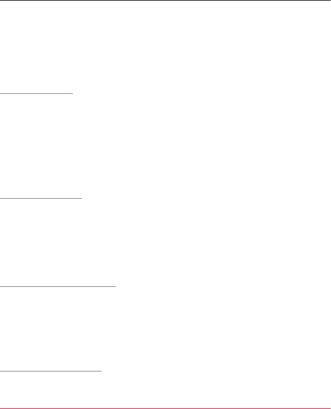
Agile Requirements Designer 3.3
b. Enter the TFS instance URL.
Format: http(s)://YourTFSServerName:8080/
c. Enter your TFS username and password.
–
Single Sign On:
a. Create a Personal Access Token in your TFS Profile.
b. Select Use API Key Authentication.
c. Enter the TFS instance URL.
Format: http(s)://YourTFSServerName:8080/
d. Enter your Personal Access Token as API key.
Configure TFS Attributes
The configuration for TFS is flexible enough to let you configure each attribute of a test case to an attribute in Agile
Requirements Designer. If your TFS test case requires a name, you can tell Agile Requirements Designer to use the
name of your stored path. This means when you are importing into or exporting from TFS, this value is populated
appropriately.
Follow these steps:
1. Connect to TFS.
2. Go to the General Configuration, TFS Tab.
3. Select any available Work Item Type in the project.
4. Select which Agile Requirements Designer attribute to map to which TFS attribute.
5. Continue to map each TFS attribute that is important, taking special notice of attributes which are required for TFS.
Import Work Items from TFS
The TFS attributes in Agile Requirements Designer are populated by the attributes mapped in your configuration file. For
more information, see Integration With Lifecycle Tools.
Follow these steps:
1. Open or create a flow.
2. Connect to TFS.
3. Drag a Work Item from the integration tree, and drop it onto the canvas.
The item is created automatically. Agile Requirements Designer creates an application link for imported Paths on the
Path level. For imported Blocks, it creates an application link under the Block properties.
Export Stored Path to TFS as Work Item
1. Open or create a flow.
2. Connect to TFS.
3. Open the Path Explorer.
4. Go to the View tab and click the Export Paths icon. Select Team Foundation Server from the drop-down list.
5. Select the user stories that you want to export and the type of export.
6. Select the project to which you want to export the user stories, and click OK.
7. Give the new user story an appropriate name and click OK.
The test suite is exported to or update in TFS.
Export Blocks to TFS as Work Item
1. Open or create a flow.
2. Connect to TFS.
189

Agile Requirements Designer 3.3
3. Make sure the export type you want is correctly mapped in the configuration for project
4. Select only the blocks on the canvas you wish to export, or select none exported all.
5. Go to the Connectors Dock, and click the 'Export Blocks' button at the bottom of the window.
6. Select the Blocks that you want to export and the type of export.
7. Select additional export options.
8. Select where you would like the items to be created and click OK.
The items are automatically created or updated in TFS.
Export Flow to TFS as Work Item
1. In the Toolbox Dock, click Connectors and select the Team Foundation Server option.
2. In the Connectors Dock, provide your credentials to log into a TFS instance.
3. In the Connectors Dock, click the 'Export Flow' button at the bottom of the window.
4. Select the type of export.
5. Select additional export options.
6. Select where you would like the items to be created and click OK.
The items are automatically created or updated in TFS.
190

Agile Requirements Designer 3.3
Test Automation
As a tester, you record automated tests and export script files that you execute with your test automation framework.
Instead of having to manually refactor and record all test variants, you use Agile Requirements Designer to automate test
script generation for your test paths.
Agile Requirements Designer can automate the generation of test scripts for any platform, be it mobile, desktop, web,
client/server, or mainframe. The only requirement is that you have an existing test automation engine available for
the platform. Agile Requirements Designer generates your test automation scripts for the test engine. The engine
then interacts with the mainframe screen, mobile device, desktop application, or web interface, respectively. Agile
Requirements Designer has been applied to many ecosystems, utilizing test engines such as eggPlant, HP UFT, Ranorex,
Selenium, and Cucumber/Gherkin, to name a few.
Automation Workflow
1. Analyze your existing test cases. Identify code snippets and variables to build the flow that describes your system.
Use predefined Keywords and define custom variables.
2. In each block of the flow, associate an action with a test code snippet and variable values for one test step.
NOTE
Variable does not support the use of a merged script in test automation. You must use a separate script to
test each script.
3. Generate and export test paths as automation scripts.
4. Run the scripts in your test automation engine.
If your test framework requires wrapper code, parameterize these prefixes or suffixes that you want to add automatically.
There is no need to create extra flow blocks to insert headers and footers into the script, as flow blocks should only
represent actions. You can generate one merged script or several separate script files. The header and footer are added
before and after the one merged script, or before and after each separate script file, respectively. For example, the header
contains code to open the browser before running the tests; the footer contains code to close the browser after running
the tests.
NOTE
Variables are not resolved when you select the merge script option in the Export Automation dialog. For
example, if you define a variable <file_name> as "^UserSelectPiece^---~SDATE~", then the UserSelectPiece is
not resolved by the script as the parameter is a variable. However, SDATE is resolved. So, in the "export
automation" dialog, the file name is "UserSelectPiece---2022-01-05_Default.txt" if the merged scripts option is
selected. (UserSelectPiece variable not resolved, the date is resolved, "_Default" is default suffix).
You can choose to exclude specific blocks or decisions from being wrapped with automation headers and footers: If
overlapping braces or actions cause you issues, go to the Automation tab of a block, and enable the "Exempt Items from
Automation Headers and Footers" checkbox for it.
Each test case can have several automation layers with different automation configurations. This feature enables you to
export several different script files for one test case.
When you log into the Test Data Manager integration (through the TDMService) and select profiles as a Target and
Source, these profiles are remembered the next time you log into the same service. They will also be used for resolving
expressions containing “T” and “S” – e.g. the @execsql()@ function.
To add automation scripts to your test flow, use the following articles:
1. Automation Scripts Examples: Learn from examples
2. Define Your Automation Configuration: Create the configuration file that contains your custom test code library
3. Construct Scripts from a Model: Layout your flow and construct your test scripts
191

Agile Requirements Designer 3.3
Automation Scripts Examples
This example shows how to use Agile Requirements Designer to generate JavaScript test cases for the
Protractor framework together with Selenium.
As a test engineer, you want to test a newly developed web interface. Your goal is to automate test generation,
so you don't have to record and edit test scripts in a manual process which could be error-prone. You use the
Protractor framework, which produces JavaScript files, together with Selenium. In this scenario, you want to test the
following workflow for the interface of a web application:
•
New users can register. The form validates their input, logs them in, and they can access the web application.
•
Existing users can log in. The form validates their input, and they can access the web application.
•
The example web application has only one function, users can delete a user, and then log out.
NOTE
This automation script example contains a flow and automation configuration.
•
Download the User_Registration_Auto.config file.
•
Download the User_Registration.vtf flow.
Overview:
1. Draw a simple first outline of the flow, with no automation yet, to get a feeling for the model.
2. Analyse your existing test scripts to identify which variables, objects, and actions you need.
3. Add objects and actions to your automation configuration.
For example, you interact with a spinbox in your script, so you need a new setValue(~Number~) function.
4. Update the flow with automation parameters for your blocks.
a. In your blocks, add the parameters available from the configuration to construct your script.
b. Go to the flow’s properties, and add variables to your flow that you want to use in the automation steps.
c. Set these variables’ values in the test data tab for the blocks where they are used, and add them to the automation
parameters.
5. Produce your test cases.
6. Export your test cases.
7. Validate that the test cases work.
Repeat these steps to refine the test flow and resolve issues.
Analyze Existing Test Scripts
You analyze your existing test scripts and determine that they need, for example, the following custom variables of type
string:
•
class names and identifiers of buttons and fields
•
URLs of the web app for verification
•
name of browser window title bar for verification
•
test input strings, such as "John" and "Smith"
•
settings for the framework to run your script
Your flow additionally requires, for example, the following objects and actions:
192

Agile Requirements Designer 3.3
•
Console — contains code that logs messages to the console.
•
Describe Path — contains code lines that start and end a test suite. It uses the flow attribute ##Path Name[p1]## as
name.
•
It — contains the code lines that start and end each test spec. It uses the block attribute ##Data Notes[b2003]##
as name.
•
Browser — contains test actions such as refresh page and go to address .
•
Element — contains test actions for clicking buttons, verifying if page elements are present, and many more.
•
Form — contains tests actions for filling in and submitting forms.
You also plan to use automation to structure your code, for example:
•
CONFIG — contains the settings that Protractor needs to decide how to run your tests, for example, the type of
browser and how to write run result reports.
•
PREVIEW — contains a header and footer that can be added when previewing a particular block's code snippets.
Build your automation configuration
After the analysis, you have identified what you need: objects, actions, and variables. Based on that, you create your
custom automation configuration.
Follow these steps:
1. Create a detailed flow for registering and logging in a user to a website.
Tip: Load User_Registration.vtf to see an example.
2. Click Tools, Properties and define variables. Save and Close.
3. Click File, Configuration, Automation, Objects and Actions. Define actions for your objects. Save and Close.
Tip: Load User_Registration_Auto.config as an example.
4. (Optional) Create a "Create Configuration" flow.
This extra flow automatically generates a configuration file for Protractor.
Tip: Load User_Registration.vtf to see an example.
Define Your Automation Configuration
Analyze your existing test scripts and identify common headers or footers, code snippets, and variables for each action.
After you build a flow for your system, you declare variables and create your automation configuration file. For more
information about variables, see How to Use Variables.
The Step Join parameter makes it possible to use the same set of automation actions as statements and expressions.
Statements include an end of line character for the respective language; for example, a JavaScript statement ends with a
semicolon and a newline character. Expressions are function calls that you can use as parameters in other function calls;
for example, JavaScript expressions do not end with a semicolon.
Choose one of the following options how to join code snippets of Actions.
•
Define code snippets as statements
End the line in each code snippet, and don't use Step Join.
Element.click();
•
Define code snippets as expressions
Do not end the line when defining each code snippet, and use the Step Join parameter to control whether a line is an
expression or a statement.
Element.click()
You control whether a particular code snippet is joined to the previous and next code snippets by the Step Join or not.
This article covers the following tasks:
193

Agile Requirements Designer 3.3
Define Automation Layers
(Optional) If you require to export several different script files for one test case, use layers to create separate and
independent automation configurations. Each layer can contain its set of objects, actions, variables, and corresponding
code snippets in different programming languages. You define an automation configuration for each layer.
When you optimize and store your paths, review the scripts for each layer on the Automation tab. When you export, each
of the layers has a separate tab, and you can export each configuration independently. For example, you can define two
layers to generate a JavaScript file and an XML test data file from one stored path.
Follow these steps:
1. Go to the Home tab and click Automation. Click the Layers tab.
2. Click the Add Layer button for each layer
3. Define properties for each layer:
–
Automation Layer Name
–
(Optional) Execution File
While designing and debugging your automation configuration, you can execute a command-line script or any
desired executable for individual generated test paths. To run the script, go to Test Factory, Export Automation, then
click the green Execute Script button. The executable runs from the local system, this option is not intended for
production use.
Example: C:\MyAutomation\bin\BuildAndRunTCB.bat ##Path Name[p1]##
–
Select Language — Defines the language of the code snippets for this layer.
–
Select Theme — Defines the syntax highlight theme for the code snippets.
–
Select Entry — Specifies how you want to enter code snippets.
•
Text
Enter code snippets for this layer by typing in a text field.
•
Spreadsheet.
Enter code snippets for this layer by pasting from a spreadsheet. For more information, see Import and Export
Snippets From Keyword-Driven Spreadsheets.
Default: Text.
4. (Optional) Define advanced properties for each layer.
–
Select objects and actions from folder location
–
Automatically map actions from a block attribute — Choose block attributes from which you want to map. For more
information how to map automation parameters from block attributes, see How to Use Variables.
5. Click Close and Save and define a file name to save this configuration if prompted.
Define Your Automation
1. Go to the Home tab and click Automation, and click the Variables tab:
a. Create variables, specify default values.
b. Click Save and Close.
2. Go to the Home tab and click Automation, and click the Export tab.
a. Select the layer to which this configuration applies under Showing Layer.
b. Define Export Details.
•
Choose for each layer whether you want to publish several Separate Scripts or one Merged Script, by default.
•
Define your default File Naming System, File Name Variable, File Prefix, and File Extension for each layer.
•
Select an Export Codec.
c. (Optional) Define Headers & Footers.
Define these fields if your automation language requires custom code inserted before, after, or between generated
elements in merged scripts.
•
Block Header Steps — (Optional) Defines a string that is prefixed before each block.
194

Agile Requirements Designer 3.3
Shell example 1:
echo "Starting ##Name[b0]##\n"
Protractor example:
it('Name: ##Name[b0]## - Description: ##Description[b1]##')
{
•
Block Footer Steps — (Optional) Defines a string that is postfixed after each block.
Shell example:
echo "Finished ##Name[b0]##\n"
Protractor example:
}
•
Path Header Steps — (Optional) Defines a string that is prefixed before each path. For example entry point
function, or include statements and global variables for merged or individual scripts, respectively.
C++ Example:
#include "FrameworkObjectidentificationLibrary.h"
std::String productName = "My application under test";
int main()
{
•
Path Footer Steps — (Optional) Defines a string that is postfixed after each path. C++ example: }
•
Path Join Steps — (Optional) Defines a string that is inserted between paths.
•
Flow Header Steps — (Optional) Defines a string that is prefixed before each flow. For example entry point
function, or include statements and global variables for merged or individual scripts, respectively.
•
Flow Footer Steps — (Optional) Defines a string that is postfixed after each flow. C++ example: }
•
Step Join Steps — (Optional) Defines a string that is inserted between steps. JavaScript example: ;\n
d. (Optional) Define Sections. Define these fields if your automation language requires custom code inserted before,
after, or between generated sections. For more information about sections, see Generate Non-Sequential Scripts
Using Dynamic Configuration.
a.
•
Name — Defines the name of the section. Must be unique.
•
Description — Defines a note to yourself how you intend to use this section.
•
Step Header — (Optional) Defines a string that is prefixed before each step in this section. HTML example:
<div>
•
Step Footer — (Optional) Defines a string that is postfixed after each step in this section. HTML example: </
div>
•
Step Join — (Optional) Defines a string that is inserted between all steps in the section. JavaScript example: ;
\n
•
Section Header — (Optional) Defines a string that is inserted before all steps of the section. Gherkin example:
Given
•
Section Footer — (Optional) Defines a string that is inserted after all steps of the section.
•
Section Join — (Optional) Defines a string that is inserted between each instance of the section.
•
Default — Designates one or more sections as the default target. This means, every time when you add an
automation step to a flow, the step is included in the selected sections by default. You can always change the
target section manually when you add an automation step that does not belong into the default section.
b. Click Save and Close.
3. Go to the Home tab and click Automation, and click the Objects & Actions tab.
a. Select the layer to which this configuration applies.
b. Use the predefined test objects and test actions, or create custom objects and actions.
c. Enter code snippets for all actions in your flows.
For more information on formats, see Import and Export Snippets From Keyword-Driven Spreadsheets.
d. Select the appropriate Step Join behavior for this line.
e. Click Insert at the bottom of the code snippet editor to insert variables into code snippets.
For more information about variables, see How to Use Variables.
195

Agile Requirements Designer 3.3
f. Click Preview Snippet (green check mark icon) to preview the code with its variables resolved.
g. Click Save and Close.
4. Continue with Construct scripts from your model.
Example Scenario: Define Automation with Statements
In this example, you want to add an automation script snippet for the First Name input field in an online form. Your code
snippets are statements, such as foo(); . You use Protractor as the test framework.
Follow these steps:
1. Go to the Home tab and click Automation. Click the Variables tab.
a. Create variables, specify default values.
Example: Create a variable named 'first_name' and set its static value to noname , or use a Data Painter function
to pick a random name from a seed table.
b. Click Save.
2. Click the Objects & Actions tab.
a. Select the layer to which this configuration applies.
b. Use the predefined test objects and test actions, or create custom objects and actions.
Examples: "Text field - verify exists", "button - click by name".
c. Enter custom code snippets for all actions in your flows.
Example: Our goal is to type the value of the 'first_name' variable into the First Name field of the form.
•
Object type: Text Field
•
Action type: Input Text
•
Code snippet:
element(by.model('FirstName')).sendKeys('...');
d. Deselect the Step Join behavior for this line.
Example: Because the code snippets are statements, you do not use Step Join.
e. Click Insert at the bottom of the code snippet editor to insert variables into code snippets. See Automation
Keywords for options.
Example:The following code types the value of the 'first_name' variable into the First Name field of the form.
element(by.model('FirstName')).sendKeys('~first_name~');
f. Click Preview Snippet (green check mark icon) to preview the code with its variables resolved.
Example:
element(by.model('FirstName')).sendKeys('noname');
g. Click Save & Close.
3. Continue with Construct scripts from your model.
Example Scenario: Define Automation with Expressions
In this example, you want to create automation script snippets so that they can be used as statements, such as foo(); ,
as well as expressions, such as bar(foo()) .
Follow these steps:
1. Go to the Home tab and click Automation. Click the Variables tab.
a. Create variables, specify default values.
Example: Create the variable ~parameter~ with the value parameterValue .
a. Click Save.
2. Click the Export tab.
a. Select the layer to which this configuration applies.
196

Agile Requirements Designer 3.3
b. Define the Step Join Parameter for the ends of statements. The parameter can be an existing object from the
same layer, or free-form text.
Example: ;\n
Default: Empty string
c. Click Save.
3. Click the Objects & Actions tab.
a. Select the layer to which this configuration will apply.
b. Create custom objects and actions for all actions in your flows. Define code snippets as expressions. For example:
•
foo()
•
bar(~parameter~)
c. Select the Step Join behavior for each line.
Example: Because the code snippets are expressions, you enable Step Join before and after actions.
d. Click Insert at the bottom of the code snippet editor to insert variables into code snippets. See Automation
Keywords for options.
e. Click Preview Snippet (green check mark icon) to preview the code with its variables resolved.
foo();
bar(parameterValue);
bar(foo());
f. Click Save & Close.
4. Continue with Construct scripts from your model.
Construct Scripts from a Model
After you define your automation configuration and flow properties, you associate actions with code snippets. Each block
in the flow has a properties window where you define the action's automation parameters. After exporting all paths as
automation scripts, you can run them in your automation tool.
Automation Variable Considerations
You can define Automation Variables for each Automation Step in four different ways:
•
Type a constant value.
•
Use a test data variable.
•
Edit a resolvable value in Data Painter.
•
Embed another step (Nested Automation Steps)
Data Painter
Test data variables can have only one value within a path, even if you use a Data Painter function. If you need a unique
value for each occurrence of the variable in the path, use a Data Painter function directly in the block.
Nested Automation Steps
You embed automation steps if you want to use actions both on their own and as evaluated expressions. A typical case
is when you need to chain actions together to build functions. For example, you can use them to implement common
standard procedures and control flow statements (for-loops, if statements, do-while, for-each, begin, try, catch, finally,
switch); or to perform operator overloading in a language-neutral way. Note that the ability to embed Automation Steps
also makes Automation Steps recursive. When the Automation Script for a path is generated, the nested step is resolved
in the same way as the other three options: The Automation Variable in the parent code snippet is replaced by the entire
code snippet of the child. The intention is to emulate functions being passed as parameters to other functions.
197

Agile Requirements Designer 3.3
Consider the following limitations when you embed automation steps:
•
You define the Automation Configuration using the Step Join. Do not define code snippets as statements with a new
line in the end of every action. The Step Join is not applied to nested Actions, only on top-level actions.
•
Nested steps are of the same Layer as their parent.
•
Nested steps cannot have a repeater.
Construct Scripts
Repeaters are helpful when you want to output, for example, a series of list items or attributes with different values. Use
Data Painter to define the functions, variables, or columns used in the code snippet.
1. Open a flow, right-click a block in the flow, and click Edit Items, and go to the Automation tab.
2. Use the Add and Edit buttons to add the required automation. In the case of a decision block, add automation for
each output.
–
Automation LayerDefines into which layer this steps belongs.
–
Automation Step TypeSpecifies one of the following types:
•
Code snippet as an Object-Action pair from configuration
(Recommended) Lets you reuse the common code snippets that you predefined in the automation configuration.
The script is stored dynamically in the automation configuration, which makes maintenance and updating easier.
Under Details, define the following properties:
•
Object Name
•
Object Type
•
Action
•
Repeater
Lets you specify a number how many variations of the snippet you want to insert. By default, the snippet is
inserted once. Set the Repeater value to 0 to indicate situations where you do not want to add the respective
automation snippet.
•
Code snippet as free-form text
Lets you insert a one-off code snippet that you have not predefined in the automation configuration. You can
insert all types of values that you can insert into a preconfigured code snippet, including automation variables,
but excluding Object Name References. The script is stored statically in the flow, which can make future
maintenance and updating more complicated if you overuse this type.
Under Details, define the following properties:
•
Use the text field to enter free-form text.
•
Repeater
Lets you specify a number how many variations of the snippet you want to insert. By default, the snippet is
inserted once. Set the Repeater value to 0 to indicate situations where you do not want to add the respective
automation snippet.
3. (Optional) Click the Sections tab to define the sections in which you want to include this step.
–
Name
Displays the names of available sections that you have defined in the Automation Configuration.
–
Description
Displays the description that you have defined in the Automation Configuration for this section.
–
Selected
Lets you define in which sections you want to include this step. You control the default selection in the Automation
Configuration.
4. Select a step.
–
Exempt Items from Automation Headers and Footers
(Optional) Specifies if to exclude specific blocks or decisions from being wrapped with automation headers and
footers.
–
Add Variables to Test Data(Optional) Defines the value of the variable in the selected line. Do one of the following:
198

Agile Requirements Designer 3.3
•
Type a constant value.
•
Use a test data variable.
•
Edit a resolvable value in Data Painter.
•
Embed another Automation Step.
5. (Optional) Click Preview Snippets (green checkmark icon) to review resolved code snippets for each layer.
6. Click Save.
Store and Review Paths
1. Go to the Manage tab and open the Path Explorer.
2. Go to the Generate Test Cases tab and click Start Optimization.
3. Click Store Path.
4. Go to the View Test Cases tab which contains the stored paths.
5. Click the Automation tab.
6. Review the fully substituted code snippets for each block, for each selected path, and for each layer.
Now you are ready to export paths in various formats, for example, as test scripts or as spreadsheet.
Export Scripts
You export paths as automation scripts to be able to run the exported files in your automation tool. You can export directly
to integrated lifecycle tools; for more information, see Integration With Lifecycle Tools.
By default, the Export Automation Scripts window prefills fields with the values that you specified on the Export tab of the
Automation Configuration for this layer.
1. Go to the Manage tab and open the Path Explorer.
2. Go to the View Test Cases tab and click Export Paths.
3. Choose Automation from the drop-down, and click Export.
The Export Automation Scripts window opens.
4. Review the scripts in each layer and define a File Name for each script.
5. (Optional) Define advanced properties.
–
Choose whether to generate a Wrapper for an external test automation tool, such as Blazemeter Taurus.
–
Define additional Header and Footer parameters for paths and blocks, respectively.
6. Decide whether you want to generate separate scripts, or one merged script.
7. Define the Script Directory where to save the files.
8. Click Export.
The automation scripts are exported.
Generate Wrapper
(Optional) If you have chosen to generate a wrapper for external test automation tools, Agile Requirements
Designer prompts you to configure the accelerator after you click Export.
1. File Name — Defines the name of the wrapper file.
2. Executor — Specifies the underlying test tool.
–
Selenium
–
Mocha
–
RSpec
–
Nose
3. Cloud Location — (Optional) Defines a server location if you want to execute your tests on a specific server when
running in the cloud, instead of allowing the cloud to choose.
199

Agile Requirements Designer 3.3
4. Script Concurrent Execution — Specifies how many scripts run at the same time, for example, the number of
simulated users in a load test.
5. Script Iteration —Specifies how often each test case is repeated.
6. Configuration Options — Defines custom configurations. Click Add Configuration to add more configurations.
Example:
modules:
cloud:
test: AgileDesigner Taurus Export
services:
- module: shellexec
prepare: npm install selenium-webdriver
7. Click OK.
Agile Requirements Designer now additionally exports a wrapper file, for example a .yml file.
How to Use Variables
While you define your automation configuration, you want to use variables in your code snippets. For more information
about how to create the configuration, see Define Your Automation Configuration.
You can assign various values to variables.
•
Static literal value
•
Predefined variable — for example results; block, flow, and path attributes; indexes
•
Data Painter function — for example first names, last names, city names, times, dates
You can perform the following operations: Declare variables, define variable values, insert variables into code snippets,
preview code snippets with resolved variables, map automation parameters from block attributes, identify unused
variables and delete Variables, bulk-import and export variables.
The default values for flow-level variables are only resolved for automation, but not when exporting paths. To export paths
with flow-level variables, assign a value to the variable in a block.
NOTE
The Test Data variables can have only one value within a path, even if a Data Painter function is used. If you
need a unique value for each occurrence of the variable in the path, use a Data Painter function directly in the
block.
Declare Variables
1. Go to the Home tab and click Automation, and click the Variables tab.
2. Select a Layer.
3. Click Add Variable and specify the following values:
a. Name: The name must start with a letter (a-z, A-Z) and can additionally contain letters (a-z, A-Z) and numbers
(0-9). The name can contain either spaces or underscores, but not both.
b. Description: Write an optional description to remind yourself how and where you intend to use this variable.
c. Type: Select one of Boolean, Date, Date & Time, String, Enumeration, File, Float, Integer, Time.
d. Default value: Define a default value; this input field adjusts to the selected type.
4. Click Save and Close.
5. Close and reopen the flow.
The new variables are available in the flow.
200

Agile Requirements Designer 3.3
Insert Variables into Code Snippets
Go to the Home tab and click Automation, and click the Objects & Actions tab. For more information, see Define Your
Automation Configuration.
1. Edit the predefined test objects and test actions, or create custom objects and actions.
2. Enter code snippets for all actions in your flows.
3. Click Insert at the bottom of the code snippet editor to insert variables into code snippets.
–
Static literal value
–
Predefined variable
For more information, see Automation Keywords.
–
Data Painter function
For more information about data resolution, see Managing Test Data.
4. Click Preview Snippet (green checkmark icon) to preview the code with its variables resolved.
5. Click Save and Close.
Define Variable Values
After you define variables, you assign them either a literal value or a Data Painter function.
1. Right-click a block and clock Edit item.
2. Click the Test Data tab.
3. Add variables to this block by doing one or more of the following steps:
–
Click Add Variable, New variable
–
Click Add Variable, Existing variable
–
Click Add Default Variable
4. Define the value by clicking one of the following buttons:
–
Edit native value
Enter a literal string or numeric value for the selected type.
–
Edit resolvable value in Data Painter
Construct data expressions by using functions that extract names from seed lists, insert characters or strings,
replace characters or strings, round off or pad numbers and strings. For more information about generating test
data, see Managing Test Data.
5. Click Save.
Map Automation Parameters from Block Attributes
You can map automation parameters from general block attributes, such as text in block or output descriptions.
This mapping lets you extract variable values from human-readable descriptions in process or decision blocks, and
automatically insert the detected values into automation scripts.
First, enable automatic block attribute mapping for the flow:
1. Go to the Home tab and click Automation. Click the Layers tab.
2. Enable the Advanced option Automatically map actions from a Block Attribute.
3. Select the block attributes from which you want to map variable values for automation, for example, Block
Description.
–
(for Process blocks) You can select Block Name, Block Description, Notes, and Data Notes.
–
(for Decision blocks) You can select Data Notes and Output Description.
4. Click Save & Close.
201

Agile Requirements Designer 3.3
For each mapping, configure the following automation:
1. Go to the Home tab and click Automation. Click the Objects & Actions tab.
2. Add Object Types and Action Types: Create actions that contain variable references, and associate them with code
snippets that use the same variables.
Example action: Into "~textField~" type "~Text~"
Example code snippet: element(by.model('~textField~')).sendKeys('~Text~');
3. Click Save & Close.
Provide the variable values in the attribute fields of blocks:
1. Return to the flow. Edit block properties or add a block.
2. Add variable values to attribute fields, in our example, to the Block Description.
Example value: Into "First Name" type "John"
3. Click Save & Close.
4. Go to the Automation tab.
You see that the automated actions have been added.
5. Export the automation scripts.
The code snippets now contain the variable values as defined in the attribute field.
Example exported script: element(by.model('First Name')).sendKeys('John');
Multi-Line Attribute Mapping Example
In this example, we create automation scripts for a login dialog. We use the eggPlant SenseTalk scripting language. The
example assumes that you have enabled the option to map actions for the Block Description field automatically.
1. Go to the Home tab and click Automation, and click the Objects & Actions tab.
2. Add the following first action: Enter "~text~" into "~textField~"
3. Pair the first action with the following code snippet:
Click(Text:"~textField~")
TypeText("~text~")
This code places the cursor into the required field and types the required text.
4. Add the following second action: Click "~element~"
5. Pair the second action with the following code snippet: Click(Text:"~element~")
6. Add a process block named "Login" to the flow.
7. Add the following pattern with the variable values to the Block Description field:
Enter "administrator" into "UserId" and then enter "pass" into "Password" and then
click "LoginButton"
8. Save your changes.
9. Go to the Automation tab of the block.
You see that several lines of automated actions have been added to the script:
Click(Text:"UserId")
TypeText("administrator")
Click(Text:"Password")
TypeText("pass")
Click(Text:"LoginButton")
Preview Code Snippets with Resolved Variables
When you look at code snippets in the configuration, you see the unresolved versions of these code snippets. Keywords,
such as variables, are substituted with their final context-specific values. It is possible to assign different values to the
202

Agile Requirements Designer 3.3
same variable across multiple blocks of the same path; in this case, only the final value is used when the variable is
resolved on path-level.
•
Code snippets in a flow are fully resolved only on the path level. You see fully resolved code in the following windows:
–
Path Explorer, Stored Paths, Automation tab
–
Path Explorer, Stored Paths, Export, Automation Scripts window
•
You can also preview code snippets in the block properties, under the Automation tab.
–
Review unresolved snippets in the table.
–
Review partially resolved snippets by clicking "Preview Snippet" (the green tick button on the lower right of the
window).
The snippet preview is partially resolved, because a block cannot know what path it is in, and it may be in none or
multiple paths. Any keywords that depend on attributes of a path are not resolved.
Bulk-Import and Export Variables
Instead of entering variables manually, you can import variables from a spreadsheet.
Follow these steps:
1. Create a three-column spreadsheet with the headers "Name", "Description", and "Default Value", and fill it accordingly.
2. Go to the Home tab and click Automation, Variables.
3. Select a layer.
4. Click Import and browse to the spreadsheet.
One sheet of custom variables is imported.
From the same dialog, you can also export a copy of your variables, review and edit the spreadsheet, and reimport them.
Identify Unused Variables and Delete Variables
Test data variables are properties of the flow in which they were created. If you delete a variable from a Block, it is still
available to all other blocks in the flow. And if you remove a variable from the Automation Configuration, it is not removed
from the flow.
It is possible that you have created test data variables that are not assigned to any block in the flow or its subflows, for
example, due to typos. Accidental duplicates can cause confusion when team members select variables.
Agile Requirements Designer can highlight the variables that exist in the flow properties, but that aren't in use.
1. Start with the parent flow and repeat this procedure with subflows.
2. Go to the Home tab and click Automation, and click the Variables tab.
3. (Optional) Click Show Unused Variables.
Unused variables are highlighted.
4. Click ... to delete test data variables that you do not need.
Note: The highlighted variables are not in use in this flow and its subflows; they may still be in use in parent flows.
Drag and Drop Automation Steps Onto the Canvas
Automation Actions is an accelerator that makes adding code snippets to blocks quicker. It also lets you start to think
about constructing a flow from a concept of a script, using an existing configuration.
TIP
Use the Automation Actions tree-view panel to quickly view the objects and actions in the configuration that is
currently open.
203

Agile Requirements Designer 3.3
You can use Automation Actions in the following ways:
Drag and drop Automation Steps From Your Automation Configuration
Use the tree-view connector panel to add actions from an existing automation configuration into flow blocks.
Follow these steps:
1. Open a flow.
2. Load an automation configuration.
3. Go to Connectors, Automation.
4. From the Framework drop-down list, select Automation Actions.
5. Select the target Layer from the drop-down list.
6. Expand a Configuration Object and add code snippets to the flow.
–
To create a new block:
a. Drag the action onto an empty space on the canvas.
b. Fill out the variables and object name of the Automation Step to be added.
c. Click OK.
A process block is created, containing a single automation step with the corresponding details of the action.
–
To add the action to an existing block:
a. Drag the action onto an existing block on the canvas.
b. If it is a decision block, select the outputs to which you want to add the action.
c. Fill out the variables and object name of Automation Step to be added.
d. Click OK.
The automation step is added to the block.
7. Repeat step 6 until the flow is complete.
Drag and drop Automation Steps From Your Ranorex Integration
Ranorex is a GUI test automation framework for testing of desktop, web-based, and mobile applications.
Follow these steps:
1. Open a flow.
2. Go to Connectors, Automation.
3. From the Framework drop-down list, select Ranorex.
4. Browse for the Ranorex repository file that you want to import.
5. From the tree listing all the objects from the repository, drag and drop the objects that you want to use.
When dragging a repository item onto a block:
–
If the block is a process, it adds the corresponding parameter to the block and allows you to select an associated
action.
–
If the block is a decision, it does the same but allows you to select outputs first.
If the item is dragged onto the canvas, a block will be created when you select an action for the repository item. That
block will then contain the corresponding parameter in its automation tab.
Update
You can verify if the objects you are using are up-to-date. The update process checks all automation parameters obtained
from the object repository and finds corresponding objects in the repository. If the location of the object in the repository
has changed, you are asked if you want to update the referenced locations in each block.
Export
204

Agile Requirements Designer 3.3
When you export automation scripts (for a stored path in the Path Explorer), the framework-specific parameters
are resolved. All parameters turn into code snippets, corresponding to their data and the language chosen in the
configuration. The framework-specific code snippets come from the corresponding section in the automation configuration.
Drag and Drop Automation Steps From Your EggPlant Integration
EggPlant Functional is a test automation tool that uses Optical Character Recognition (OCR) to identify objects to interact
with on mobile, desktop, or web applications. It runs scripts written in its own scripting language, SenseTalk.
The EggPlant connector allows you to take images from an EggPlant project and use them as variables in code snippets
of SenseTalk scripts.
A tree-view connector panel for incorporating images found by TestPlant EggPlant Functional is available, allowing you to
produce SenseTalk scripts.
There are two ways to add objects and actions to blocks:
•
Dragging and dropping EggPlant images
•
Typing code directly in the block using the autocomplete functionality
Add objects and actions by dragging and dropping images
1. Open a flow.
2. Load a configuration for EggPlant (SenseTalk) scripting.
3. Go to Connectors, Automation.
4. From the Framework drop-down list, select EggPlant.
5. Browse for an EggPlant suite. Images from the EggPlant suite will be shown in the tree.
6. Drag an EggPlant image onto the canvas.
A pop-up is created for choosing the Object and Action of the parameter you want to add.
7. Select an action that uses an EggPlant image as a variable, or at least an action that has a variable.
The name of the image should appear in the first variable of the current action.
8. Click OK.
Repeat this procedure to create a model that generates SenseTalk scripts.
Add objects and actions by typing code in block properties
First, create a code-completion-enabled configuration.
1. Go to File, Configuration, Automation.
2. Create a new automation layer.
3. In the Objects & Actions Tab, add an object and actions.
When you add actions that have variables in them, include the variable in the name of the action. For example, you
could have an action named " Enter Text "~TEXT~" " with a snippet: " App.WriteText("~TEXT~"); ".
4. Save the configuration.
Now you can start adding the code.
1. Double click a block or right-click and select Edit Item.
2. On the General tab, start typing the name of an action available in the currently loaded configuration, into a field that
has been enabled for code completion (for example, Description).
3. Select the desired Action from the drop-down list.
If the Action has any variables identified by its name (marked between tildes), then they will be highlighted in yellow
and the first variable in the completed action name will be selected.
4. Start typing the EggPlant image name, select it from the completion list and press Enter. The image name should now
have replaced the placeholder for the variable in the action name in the field.
205

Agile Requirements Designer 3.3
5. Go to the Automation tab. A corresponding action should have been created, with the image name as a variable in it.
Repeat this procedure to create a model that generates SenseTalk scripts.
Import and Export Snippets From Keyword-Driven Spreadsheets
As test engineer, you may want to use a keyword-driven framework to maintain an abstract definition of test cases in
spreadsheets. With Agile Requirements Designer, you can import rows and columns in spreadsheet formats, automate
their generation through a flow, and export them in a format that you can process further.
The alternative to maintaining data in tables is the default entry method where you type (rather, copy and paste) snippets
into a text field.
Follow these steps:
1. Click File, Configuration, Automation.
2. Click the Layers tab and choose Spreadsheet from the Select Entry combobox.
You have switched from the default text entry method to a table-based entry method.
3. Click the Objects & Actions tab, and select an action.
4. Use one of the following methods to input the code snippets.
Note: The buttons only appear if you have switched the Select Entry type to Spreadsheet on the Layers tab.
–
CSV:
a. Click Import.
b. Choose CSV format depending on the input file type.
c. Copy the CSV data into the clipboard and press ctrl-V to paste the data into the import dialog.
d. Click Import.
The rows and columns are associated with the action.
–
Excel Spreadsheet:
a. Open your spreadsheet, and copy the data into the clipboard.
b. Return to the dialog in Agile Requirements Designer.
c. Click Paste Table Data, or select a cell and press ctrl-V.
The rows and columns are associated with the action.
5. (Optional) If you need to change the number of columns or rows, click Resize Table on the Objects & Actions tab.
6. Insert your variables into cells and replace static text where applicable.
After you have defined your automation configuration and flow properties, you associate actions with keywords. Each
block in the flow has a properties window where you define the action's automation parameters.
Follow these steps:
1. Open a flow, right-click a block in the flow, and click Edit Items. Go to the Automation tab.
2. Add the required automation in the blocks' Output Details tabs. In the case of a decision block, add automation for
each output.
3. Define the script parameters:
–
Object Type: Text Field
–
Action: Input Text
–
Define the value of the variable. Do one of the following:
– •
Type a constant value.
•
Use a test data variable.
•
Edit a resolvable value in Data Painter.
Note: Test data variables can have only one value within a path, even if a Data Painter function is used. If you
need a unique value for each occurrence of the variable in the path, use a Data Painter function directly in the
block.
206

Agile Requirements Designer 3.3
4. Review the generated paths:
a. Open the Path Explorer, click Start Optimization and optimize paths.
b. Click Store Path.
c. Go to the tab containing the stored paths.
d. Click the Automation tab to review the fully substituted rows and columns for each block for each selected path.
After you have reviewed the output, you can generate and export keyword-driven spreadsheets.
Follow these steps:
1. Go back to the Generate tab and click Export Paths.
2. Define a file name for the output file.
3. Choose Spreadsheets from the drop-down, and click Export.
Manage Automation Configuration Files
By default, Agile Requirements Designer stores automation configurations in one file. For more complex test sets, you
have the option of maintaining configurations in separate files in a version-controlled directory structure. Using the Git
Connector to manage complex configurations brings the following advantages:
•
Storing configurations in separate files enables you to use features of your integrated development environment (IDE)
to edit code snippets.
•
Integrated file version control enables your team to track revisions of configuration files in Git repositories.
•
You can call Git commands such as merge, pull, and push right in the Agile Requirements Designer interface, and do
not need to switch to the command line.
NOTE
The Git Connector provides very limited functionality for managing automation scripts through Git. For a more
complete solution, we recommend using a full-featured Git GUI application. For more information on how to
enable the Git Connector, see Enable Standard Settings and Advanced Features.
Configure the Git Connector for Automation Configurations
Agile Requirements Designer supports file version control with Git. In the following we assume that you have already
installed a Git client and cloned a repository.
Follow these steps:
1. Set up a folder to store objects and actions in directories and files:
a. Click Home, General Config.
b. Click the Load button in the top, and select the directory where you store the general configuration files.
c. Click Save & Close.
d. Click Home, Automation.
e. Click the Load button in the top, and select the directory where you store the automation configuration files.
f. Click Save & Close.
2. Click Home, General Config. Click the GIT File Status tab.
a. Click the General Configuration tab and define the Git Folder for the general configuration file.
b. Click the Automation Configuration tab and define the Git Folder for the automation configuration file.
c. Click the Automation Scripts tab and define the Git Folder for the automation scripts file.
d. Click Save & Close.
3. Click Home, Automation, and click the Layers tab. For each layer, do the following:
a. Enable Advanced, Select objects and actions from folder location.
b. Enter your local Git repository location in the Advanced, File Structure Location field.
207

Agile Requirements Designer 3.3
c. Define your Git Remote Name.
d. (Optional) Enable one or more of the following options:
If you enable both options, Agile Requirements Designercommits and pushes configuration changes when you
click Save in the Automation Configuration window.
•
Commit changes to local branch when saving
•
Push changes to remote origin when saving
e. Click Save As and close.
The Commit changes and Push changes check boxes do not depend on each other. For example, you can have a
previous commit that you have not yet pushed. In this case, if the Commit changes option was disabled and the Push
changes check box was enabled, then nothing would be committed, but the previously un-pushed commit would be
pushed.
To create a new configuration without overwriting the current configuration, use Save As and save a copy under a new
name.
Create a File Structure
The code snippet editor in Agile Requirements Designer does not have any advanced editing features. You may want to
use an IDE to open the files from the Automation Configuration directory, and edit more complex code snippets in your
preferred source editor to make use of error handling and IntelliSense.
Your Objects & Actions have an implicit tree structure:
Object Type Action Type Code Snippet
Click Create List ...
Open Application ...
Validate Exists ...
Open Click ..
Press Keys ...
Rather than applying a configuration to each layer, you can set up a file structure in your git repository.
•
C:\MYGIT\
–
Click\
•
Create List.txt
•
Open Application.txt
•
Validate Exists.txt
–
Open\
•
Click.txt
•
Press Keys.txt
Share Configurations
You can use Git on the command line to share configurations, or in Agile Requirements Designer. For details, see the Git
documentation.
1. Click Home, General Config.
2. Click the GIT File Status tab.
3. Select a target Branch.
4. Use Git commands to receive or submit changes to configuration files.
208

Agile Requirements Designer 3.3
–
Pull - download others' changes from repository
–
Push - upload your changes to repository
–
Settings
–
Merge - merge branches
–
Delete - delete a branch
–
Branch - make a new branch
–
Clone - download an existing repository and its history
–
Commit - record change snapshot of this branch in history
–
Push changes immediately
BlazeMeter Automation
The BlazeMeter Automation tab offers similar functionality as the Scriptless Scenario Editor in BlazeMeter, right inside
the ARD desktop app. For more information about BlazeMeter Scriptless Testing features, see Creating a Scriptless
Functional Test in the BlazeMeter Guide.
The following video gives you an overview of the workflow and supported features of the integration.
In this article about test automation for BlazeMeter, we refer to the following concepts: Objects are UI elements of your
web application under test, such as buttons, menu items, or input fields. Actions are standard test actions such as clicking,
selecting, or typing. Groups are reusable, custom sequences of Actions that are applied to Objects. For more information
about BlazeMeter concepts used in this integration, see Integrate With BlazeMeter.
209

Agile Requirements Designer 3.3
In ARD Studio, link an ARD flow to a BlazeMeter workspace to load available Objects and Groups. After the link has been
established, you can attach BlazeMeter automation to blocks. Same as with code snippets, you can attach one or more
Actions to process blocks, or to each output of a decision block, respectively.
1. Open a flow that is linked to a BlazeMeter workspace.
2. Edit a block and go to the BlazeMeter Automation tab. ARD lists Actions, and loads Groups and Objects from your
Workspace.
3. If you have added or modified a Group or Object in BlazeMeter, click Reload Groups and Objects.
4. Click an Action or Group to add automation steps.
Tip: Use the search box to find Groups in the Groups tab.
5. For each Action, select a target Object and define parameter values as applicable.
6. Go to the BlazeMeter tab and click Validate.
The Validation window opens with the BlazeMeter Automation tab selected.
7. Click Validate Flow to identify and fix any errors in the scenario.
8. Save the flow.
Edit Automation
Open a flow that is linked to BlazeMeter workspace. Edit a block and go to the BlazeMeter Automation tab to edit the
automation.
•
To reorder steps, drag the handle in the middle of the left edge, and drop the action into a new position within the
scenario.
•
To remove a step, click Delete.
•
You can use DataPainter variables (such as ^url^ or ^test_name^ ) as parameter values. Values are resolved
before export; this means that using ARD variables does not create BlazeMeter Test Data Parameters.
•
When creating automation for multiple Display Outputs of a decision block, you can copy and paste automation
between outputs.
a. Define automation for the first output.
b. Select the first output and click Copy Steps.
The Select Outputs dialog opens.
c. Mark the target outputs with a checkmark, and click OK.
The automation is copied from the first to the target outputs and the dialog closes.
d. Select the target outputs and edit the copied steps as needed.
How to Edit Objects, Groups, and Actions?
•
The list of Actions is fixed and cannot be edited. The list reflects test actions supported by the Selenium framework.
•
The Object dropdown inside an Action step is initialized with values loaded from the linked BlazeMeter workspace. If
Objects are broken or missing, visit the GUI Functional > Test Action Library screen in BlazeMeter to edit them.
•
The Groups tab is initialized with values loaded from your linked BlazeMeter workspace. If Groups are broken or
missing, visit the GUI Functional > Test Action Library in BlazeMeter to edit them.
For more information about how to create and edit Objects and Groups, see Test Action Library in the BlazeMeter Guide
How to Assign Values to Parameters Inside Groups?
You create Groups in BlazeMeter, and use them in Agile Requirements Designer. But in Agile Requirements Designer,
you cannot expand Groups to edit the parameter values inside. Often you will want to assign variable values generated by
DataPainter.To be able to assign parameter values from inside Agile Requirements Designer, follow these steps:
1. In BlazeMeter, create or edit the Group in a GUI Functional Test.
2. Replace each value with a unique test data parameter.
210

Agile Requirements Designer 3.3
Example: In a Type action, replace the Text: value "Iqaluit" with the new variable ${canadian_city} .
3. Click Overwrite Original to save your changes in the Test Action Library.
4. Note down the variable names that you used for reference.
5. In Agile Requirements Designer, edit the block and open the BlazeMeter Automation tab.
6. Insert one of the Store Actions (Store Eval, Store String, Store Text, Store Title) and define a variable and value..
Example: Insert a Store String action, and define Variable: canadian_city to be
Text: "@randlov(0,@seedlist(Canadian Cities)@)@" .
The Store Action generates a different global variable value for every path (test case).
7. Insert the Group.
The Group uses a different global variable value in every exported test case.
For more information about Store Actions such as Store Eval, Store String, Store Text, and Store Title, see Taurus Actions
for Scriptless Functional Testing in the BlazeMeter Guide. For more information about creating and editing Groups, see
Test Action Library in the BlazeMeter Guide
Review Automation
After you have added Automation to individual blocks or outputs, you can review your automation from the canvas. The
BlazeMeter icon helps you identify quickly which blocks have automation defined.
1. Open a flow
2. Go to the BlazeMeter tab and click View Steps.
The preview pane opens.
3. Select a block or output with a BlazeMeter icon to view its automation in the preview pane next to the canvas.
4. Click Edit Steps to open the BlazeMeter Automation tab.
Generate and Export Paths
After you have defined automation steps for blocks, you export paths as test scripts to BlazeMeter. To update test scripts,
edit them in ARD and export them again; the export overwrites and refreshes the generated tests in BlazeMeter. Don't edit
ARD-generated test cases in BlazeMeter.
Follow these steps:
1. Click Manage > Path Explorer, and generate and store your paths as usual. For more information, see Path Explorer
and Store Paths.
2. In the stored path view, go to the Automation tab and review the paths.
3. Click Export Paths and select BlazeMeter. The Export Paths to BlazeMeter window opens.
4. Select a target project. The Action column shows you whether exporting will create new tests, or update existing
tests in this project.
5. Do one of the following:
–
Select Export to Project: Your project to have BlazeMeter import these paths as individual tests.
–
Select Export to Project: Your project and define a Test Suite Name to store the tests in a new test suite.
–
Select Export to Project: Update in any project to update the tests in the same project where you exported them
before, if applicable.
6. Wait for ARD to complete the export.
7. Go to the External Links tab and open the provided BlazeMeter.com link.
TIP
You can export the paths from a flow that uses BlazeMeter automation from a workspace into multiple projects,
and also into multiple test suites, and treat them as independent tests. You control the update behavior under
BlazeMeter > Settings > Export > Check whether existing links can be updated.
211

Agile Requirements Designer 3.3
•
When you enable this option, the exporter identifies to which project you exported these paths previously,
and automatically offers to update the tests there; the dropdown option "Update in any project" is
preselected.
•
When you disable this option, the exporter doesn't identify previous target projects automatically, and the
dropdown option "Update in any project" is not available. In this case, expand the project dropdown and
select the target project.
Run Test Scripts in BlazeMeter
1. Open the test case or test suite on BlazeMeter.com. The test name contains a reference to the ARD flow.
2. Define the Location where to run the tests.
3. Define the Browsers in which to run the tests.
4. Click Run Test to execute the tests in BlazeMeter.
5. Go to the Reports tab to view the test results.
212

Agile Requirements Designer 3.3
Reference
This section contains reference material regarding Automation Keywords, Data Painter Functions, and how to Install HPE
ALM Service.
ARD Hub User Roles and Permissions
ARD Hub supports two System Roles:
•
Administrator
Administrators manage the system configuration and can create and manage projects.
•
User
Users are the Viewers, Editors, or Project Administrators who use the system.
Permissions System Administrator Project Admin (User) Project Editor (User) Project Viewer (User)
Users
Add / Remove System
Administrators
Yes
Manage User Access to
Projects
Yes
Projects
View Projects Yes Yes Yes Yes
Create Projects Yes
Rename Projects Yes
Delete Projects Yes
Versions
View Versions Yes Yes Yes Yes
Create Versions Yes Yes
Rename Versions Yes Yes
Delete Versions Yes Yes
Update Versions' Subflow
Links
Yes Yes
Folders
View Folders Yes Yes Yes Yes
Create Folders Yes Yes Yes
Rename Folders Yes Yes Yes
Delete Folders Yes Yes Yes
Flows
View Flows Yes Yes Yes Yes
Create Flows Yes Yes Yes
Edit Flows Yes Yes Yes
213

Agile Requirements Designer 3.3
Permissions System Administrator Project Admin (User) Project Editor (User) Project Viewer (User)
Lock Flows/Unlock
Own Flows
Yes Yes Yes
Unlock Any Flows Yes Yes
Rename Flows Yes Yes Yes
Move Flows Yes Yes Yes
Delete Flows Yes Yes Yes
Migrate Flows Yes Yes Yes
Generate Flow Image Yes Yes Yes
As an Administrator, you can review this information inside the ARD web interface. Navigate to the System Administration
screen, go to the Project Management tab and click Roles and Permissions.
Automation Keywords
Code snippets in the automation configuration have a selection of keywords available that represent various attributes and
have different rules for how they are resolved.
To use the automation keywords that are listed in this reference guide, click File, Configuration, Automation, go
to the Objects & Actions tab, and click Insert. For the detailed procedure how to use these keywords, see the Test
Automation section.
Object Reference
A keyword which represents the object name of the automation parameter that references the action of the code snippet.
##OBJ_NAME##
Variable References
A keyword that represents a variable in a flow. Variable keywords can be specified with any text in between two tilde ('~')
signs. You can have multiple variable references with the same name.
~VariablePlaceholderName~
Attribute References
Attribute references are keywords that resolve to different properties of the flow, path or block, like their names or
descriptions.
Block Attribute Values
Block Attribute Name Keyword
Block Type ##Block Type[b3]##
Complexity ##Complexity[b6]##
Data Notes ##Data Notes[b2003]##
Data Sensitivity ##Data Sensitivity[b10]##
Description ##Description[b1]##
214

Agile Requirements Designer 3.3
Documentation ##Documentation[b22]##
Expected Results ##Expected Results[b2006]##
False Description ##False Description[b1001]##
Name ##Name[b0]##
Notes ##Notes[b2]##
Observability ##Observability[b5]##
Output Description ##Output Description[b8002]##
Probability ##Probability[b2002]##
Process Output Text ##Process Output Text[b1002]##
Requirements IDs ##Requirements IDs[b18]##
Status ##Status[b4]##
Test Importance ##Test Importance[b8]##
True Description ##True Description[b1000]##
Path Attribute Values
Path Attribute Name Keyword
Author ##Author[f2]##
Description ##Description[f3]##
Title ##Title[f1]##
Version ##Version[f4]##
Flow Attribute Values
Flow Attribute Name Keyword
Creator ##Creator[p7]##
Date Created ##Date Created[p8]##
Date Modified ##Date Modified[p9]##
Details ##Details[p6]##
Import Source ##Import Source[p5]##
Modification History ##Modification History[p11]##
Notes ##Notes[p14]##
Override Importance ##Override Importance[p12]##
Path Name ##Path Name[p1]##
Source ##Source[p4]##
Test State ##Test State[p13]##
Version Created ##Version Created[p10]##
215

Agile Requirements Designer 3.3
Index References
Block Index
The Block Index keyword is substituted with an integer value when a code snippet is resolved on the path level. It
resolves to the number of blocks that the current path has been through to get to the code snippet that contains this
keyword.
##BLOCK_INDEX##
Automated Block Index
The Automated Block Index behaves the same way as the Block Index; an integer, resolved on the path level. It
resolves in the same way as the Block Index, but only counts blocks that contain Automation Parameters.
##AUTO_BLOCK_INDEX##
Automated Parameter Index
The Automated Parameter Index is an integer, resolved on the path level. It resolves to the number of Automation
Parameters that the path has been through to get to the code snippet that contains this keyword.
##AUTO_PARAM_INDEX##
Run Result
You can map test run results to paths and blocks by adding block and path references to automation scripts.
Store paths using Path Explorer, open the View tab, and export the scripts; then run the test in your test automation
framework.
After the tests are completed, open the View tab in Path Explorer and import the run results from a test execution result
file. The importer connects to the appropriate repository and updates each flow file. The test results are available on
the Runs tab of the Details View Dock in Path Explorer.
Global Path Reference
The Global Path Reference keyword is substituted with a unique path identifier (referring to the repository, flow, and path
ID).
##GLOBAL_PATH_REF##
Global Block Reference
The Global Block Reference keyword is substituted with a unique block identifier.
##GLOBAL_BLOCK_REF##
Instance and Script Attributes
Instance Attribute Name Keyword
CA ARD installation directory, for example, C:\Program Files\CA
\AgileDesigner
##ARD_INSTALL_DIR##
Agile Designer Automator directory, for example, C:\Program Files
(x86)\CA\AgileDesignerAutomator\
##ADA_INSTALL_DIR##
216

Agile Requirements Designer 3.3
Location of this flow file or repository ##FLOW_LOCATION##
The script name ##GLOBAL_FILENAME_REF##
Example video
The following video demonstrates how you import run results directly from JUnit into Agile Requirements Designer using
the ##GLOBAL_BLOCK_REF## keyword:
Data Painter Functions
DataPainter uses Test Data Manager integration (TDMService) functions to generate test data. The DataPainter screen
contains built-in documentation. For the full description of valid arguments and values, see Data Generation Functions
and Parameters in the TDM documentation.
TDM Data Painter integration in ARD supports creating and using the custom-built functions in the TDM portal. For more
information, see Custom Metafunctions.
Function Feature
11PROOF() Finds the next Elfproef number from the sequence.
ABS() Returns the absolute value.
ADD() Adds two values together.
ADDCHECKSUM() Adds special LUHN, VERHOEFF or CB checksum.
ADDDAYS() Adds a number of days to a date.
ADDLUHN() Adds a Luhn checkdigit.
ADDMILLISECS() Adds a number of milliseconds to a timestamp.
ADDMOD97() Uses modulo97 as checksum code.
ADDMONTHS() Adds a number of months to date.
ADDRAND() Adds a random number within a range to the number.
ADDRANDDAYS() Adds a random number of days within a range to the date.
ADDSECONDS() Adds seconds to a datetime value.
ADDVERHOEFF() Adds Verhoeff checksum for error detection.
ADDYEARS() Adds years to a date.
ALPHANUM() Extracts all non-alphanumeric characters from a string.
ASC() Returns the ascii code of the first character of the string.
ATSIGN() Returns the value "@".
CARET() Returns the value "^".
CASE() Returns the value associated with the first test that is true, otherwise returns a default value.
CHAR() Returns the ASCII glyph of a decimal number.
COLLAPSE() Removes all space, tab, carriage return, and new line characters from a string.
CONVBASE() Coverts the string to a different base.
COUNT() Counts the number of items in the list or related rows in another table.
COUNTLIST() Returns the number of rows returned by specified SQL query.
DATE() Returns a string as a date.
DATETIME() Returns a specific string as a date and a time.
217

Agile Requirements Designer 3.3
DAYSAFTER() Returns the difference in days between the end date and the start date.
DIVIDE() Divides the first number by the second.
DOB() Adjusts a date of birth preserving a random age within a range.
DOW() Returns the day of the week for the date specified.
ELEMENT() Splits or parses a string into parts based on a designated character.
ENVVAR() Reads in an environment variable.
EXECSQL() Issues SQL to either the R(Repository), S(Source) or T(Target) connection.
EXECSQLCOUNT() Returns the count of records returned by the specified SQL query.
GETSQL() Returns the specified stored SQL from the repository. Useful in conjunction with @sqllist()@
EXP() Returns a number to the power of x.
GROUP() If you have a number of items grouped into blocks of a certain size, then this function returns the
number of the group that a particular item belongs to.
GUID() Returns a globally unique identifier.
HASH() Returns a hash value for a number.
IBAN() Creates a random IBAN.
IF() Tests the Boolean and returns the first expression if true, and the second expression if false.
IFNULL() Returns the first expression unless it is null, in which case it returns the second expression.
JDATE() Converts the date to and from a Julian date.
LASTDAY() Returns the last day of the month.
LEFT() Returns the leftmost characters from the string.
LEFTPAD() Left-pads the string with spaces or other characters.
LEFTTRIM() Removes the chosen characters from the left side of the string.
LENGTH() Returns the number of characters in the string.
LOG() Returns the natural log of a number.
LOGTEN() Returns Base 10 logs of a number.
LOV() Returns a specific row from a SQL query.
LOWER() Returns the string in lower case.
LUHN() Returns a number of the given length including a check digit using the Luhn algorithm.
MAX() Returns the maximum value in a list.
MEAN() Returns the mean of a list of numbers.
MID() Returns the substring starting from the given position.
MIN() Returns the minimum value in a list.
MOD() Returns the modulo (remainder of first number divided by second number).
MULTIPLY() Multiplies the two numbers.
NEXTSTRINGVAL() Returns the next value in the specified sequence as a string.
NEXTVAL() Returns the next value in the specified sequence.
OCCURS(S) Counts the number of occurrences of a particular character.
OCCVAL() Returns a random value from a list of values using a number modifier.
PERCVAL() Returns a random value from a list of values using a percentage modifier.
POS() Returns the first position of a piece of text in the string.
RANDCHARS( ) Returns a random string consisting only of the specified characters.
RANDDATE() Returns a random date between the minimum and maximum values.
218

Agile Requirements Designer 3.3
RANDDIGITS() Returns a random string of digits of length between the min and max.
RANDEXP() Returns a positive number on an exponential distribution with a mean as specified.
RANDHEX() Returns a random hex string of a random length between the minimum and maximum bytes.
RANDLOV() Lets you select a random element from a list of values. For all arguments and options, see Data
Generation Functions and Parameters in the TDM documentation.
RANDNORM() Returns a normally distributed number between the min and max values, with the specified mean and
standard deviation.
RANDNULL() Sets a percentage of the values to null. The non null values will contain the result of the expression.
RANDRANGE() Returns a random number within a range.
RANDTEXT() Creates random text of length within a range.
RANDTIME() Returns a random time.
RANDVAL() Generates a more or less unique but not sequential number.
REPLACE() Returns the string with substrings replaced as specified.
REPEAT() Repeats the value the specified number of times, separated by separator.
REVERSE() Returns the reverse of the specified string.
RIGHT() Returns the specified number of characters from the right of the string.
RIGHTPAD() Pads the string to the maximum size of the column.
RIGHTTRIM() Trims characters from the right hand end of string.
ROUND() Rounds a number up to the defined decimal place.
SECONDSAFTER() Returns the total seconds between start and end.
SEQLOV() Lets you select elements from a list of values sequentially. For all arguments and options, see Data
Generation Functions and Parameters in the TDM documentation.
SIGN() Returns the sign of a number.
SINE() Returns the sine of the counter.
STDDEV() Returns the standard deviation for the specified list of numbers.
STRING() Converts the number into a string based on a number or date format.
SUBTRACT() Subtracts the two given number.
SWEDEN_SSN() Returns a Swedish Social Security Number.
TILDE() Returns the tilde character "~".
TIME() Returns the time from the string.
TRIM() Trims characters from both ends of the string.
UK_NINO() Returns a random UK National Insurance number.
UPPER() Returns the string in upper case.
US_SSN() Returns a random US social security number with the specified separator.
VERHOEFF() Generates a random number with its Verhoeff checksum test, or else returns false.
WORDCAP() Converts the first letter of each word in the string to upper case.
Install HPE ALM Service
The HPE ALM Service is part of the Test Data Manager installation. If you have installed a stand-alone instance of Agile
Requirements Designer (without Test Data Manager) and want to connect to HP Quality Center through the Service,
you have to install the HPE ALM Service manually. This section takes you step by step through the installation and
configuration process for installations with a MS SQL database.
219

Agile Requirements Designer 3.3
NOTE
We recommend that you connect to your HPE ALM instance using the REST API. It's the simpler method and
does not require any configuration or installation. The REST API does not support importing BPTs. If you require
to import BPTs, connect through the GT HPE ALM Service, as described in this installation article.
Related Articles
•
Download Test Data Manager from CA/Broadcom Support
•
Verify Prerequisites for ALM Integration (TDM documentation)
•
Configure ALM Integration (TDM documentation)
Install and Configure the Service
1. Install the Microsoft SQL Express to create an instance.
a. Within a database in the server, run the provided scripts SQLserverGT_web_log.sql and
gtrep_insert_web_log.sql to add a table and a procedure to the database. You can find the scripts in the
<installation_path>\Scripts\SQLServer directory.
b. Ensure that that TCP/IP is enabled for this server:
a. Open SQL Server Configuration Manager, SQL Server Network Configuration, Protocols for your server
name.
b. Right-click on TCP/IP and select Enable (you might be required to restart the computer).
2. Enable the group policy settings:
a. Type gpedit.msc in the command prompt and press Enter.
b. In the policy editor navigate to this node: Computer Configuration, Administrative Templates, System, User
Profiles.
c. Under the User Profiles pane on the right, set the policy Do not forcefully unload the user’s registry at user
logoff to Enabled.
3. Add a firewall exception:
a. Go to the Start menu, type wf.msc in the search field and press the Enter key.
b. Click Inbound Rules, New Rule and select Port.
c. Enter the port which the ALM service will use (typically, 8095) in Specific local ports and click Next.
d. Select the Allow the connection option and click Next.
e. In the Profile dialog, select all options.
f. Provide name and description for the rule (for example, "Opened port 8095 for Grid-Tools ALM") and click Finish.
4. Download ALM client registration.
Running Internet Explorer in administrator mode, go to the URL of the ALM you are connecting to (for example, http://
alm.yourcompany.com:8080/qcbin/) and click Tools, HPE ALM Connectivity, Download.
5. Install the HPE ALM service by running the setup_GTALMService.exe file.
6. Go to C:\Grid-Tools\GTHPALMService\GTHPALMService_ConfigEditor , open the
ALMserviceConfigEditor.exe and configure the first tab:
a. ALM URL: the same one as earlier (for example, http://alm.yourcompany.com:8080/qcbin/)
b. Service address: http://localhost:8095/ (replace the * with localhost)
c. ALM Version: ALM 12 Patch
d. Click Verify to test whether you have access.
7. Edit the Connection String tab:
a. Data Base: SQL server.
b. Data Source: Enter the name of the instance that you created.
c. Username/Client ID: Enter a username to log in to the server. If you are using integrated security, enter 'admin'.
d. Password/API Key: Enter the corresponding password. If you are using integrated security, enter 'admin'.
220

Agile Requirements Designer 3.3
e. Initial Catalog: Enter the name of the database where you installed the tables from before.
f. Click Verify and Save. If using you are integrated security, this will not connect yet.
8. Edit Log configuration
Specify exactly the same settings as on the Connection String tab.
9. If you are using Windows integrated security, edit the config file:
a. Close the ALMserviceConfigEditor.
b. Open GTHPALMServiceConsole.exe.config located in C:\Grid-Tools\GTHPALMService\ .
c. Find add name="connStr" connectionString= .
d. Replace any user ID and password with Integrated Security=True
Example: connectionString="Data Source=SMITH01;Integrated Security=True;Initial
Catalog=HP_ALM_TEST;Network Library=dbmssocn;"
e. Find connectionString value=. There should be two locations, one for Oracle servers, one for Microsoft
SQL. Edit the SQL one.
f. Replace the userID and password fields with IntegratedSecurity=True .
g. Save and Close.
The service is installed and configured.
10. Start the Service
a. Open the ALMserviceConfigEditor.
b. Verify all the tabs. The log tabs have empty username and passwords if you are using Windows integrated security.
c. Go to the Status tab and click Create Task.
d. Enter the username and password details for the machine you are working on.
e. Click Start Service.
The service starts running.
Now you are ready to connect, map attributes, and start using the integration. For more information, see Integrate With
HPE ALM (GT HPE ALM Service).
Path Naming Template Functions
When you store multiple paths (test cases), you generate path names for them by combining literal text and template
functions. Examples: “Test Case {Path No} of {Total No}” generates paths names such as “Test Case 1 of 100”, “Test Case
2 of 100”, etc.
You can use the following Path Functions to generate Path Name and Path Description (Header and Footer):
•
{First Block} Returns the name of the first block, excluding the Start block.
•
{Middle Block} Returns the name of a block in the middle of the path.
•
{Last Block} Returns the name of the last block, excluding the End block.
•
{Steps Total} Returns the total number of steps in this path, not counting Start and End blocks.
•
{Paths Total} Returns the total number of paths for the current optimization. Example: {Path No}/{Total No}.
•
{Path No} Returns the sequential number of this path. Ensures unique path names. Example: {Path No}/{Paths Total}.
•
{Next} Returns a sequential number. Ensures unique path names.
•
{Blocks} Returns an existing block name that you want to include in the path name. Select the Block from the list.
•
{Edges} Returns an existing edge name that you want to include in the path name. Select the Edge from the list.
•
{Decision Outputs} Prompts you for a number n and returns the concatenated names of the first n decisions and
their chosen outputs. Entering 1 returns the first decision, 2 returns the first and second decisions, and so on.
Example: “Test Case {Decision Outputs}{2}” generates path names such as “Test Case TradeCurrency=EUR
VestingCurrency=GBP”, “Test Case TradeCurrency=YEN VestingCurrency=USD”, etc.
You can use the following Flow Functions to generate Path Name and Path Description (Header and Footer):
221

Agile Requirements Designer 3.3
•
{Flow Title}
•
{Flow Author}
•
[Flow Description}
•
{Location Path}
•
{ARD Hub URL}
•
{Flow Link}
•
{Version ID}
•
{Documentation}
•
{Source Edit}
•
{Environment}
•
{Audit}
You can use the following Block Functions when generating the Path Description Body:
•
{Block Name} Returns the block name.
•
{Block Extended Name}
•
{Block Description} Returns the content of this block’s description field.
•
{Block Extended Description}
•
{Decision Output} Returns the chosen output edge in this path for a Decision block. For a Process block, it always
returns an empty string.
•
{Block No} Returns the sequential number of this block. Ensures unique block names. Example: “Block {Block No} of
{Blocks Total}”
•
{Blocks Total} Returns the total number of blocks in the path. Example: “Block {Block No} of {Blocks Total}”.
•
Block Type
You can additionally use the following Block Functions when generating the Path Description Body if you have defined
these fields in the Block Properties:
•
Black Box
•
Complexity
•
Data Nodes
•
Data Sensitivity
•
Expected Results
•
Notes
•
Observability
•
Probability
•
Requirement IDs
•
Block Status
•
Test Importance
•
Virtualization Parameters
The Path Description is the concatenation of the Path Description Header, followed by the Path Description Bodies for
each unfiltered block in the path, followed by the Path Description Footer.
Path Description Example
•
Header: This is path {Path No} out of {Paths Total}.
•
Body: Decision {Block No} with name "{Block Name}" and description "{Block Description}"
selects "{Decision Output}".
•
Footer: This path ended in state {Last Block}.
Generates for example the following path description:
222

Agile Requirements Designer 3.3
This is path 4 out of 12.
Decision 1 with name "Choose day" and description "date stamp" selects "2020-01-15".
Decision 2 with name "Preferred time" and description "time slot" selects "10:00-12:00".
Decision 3 with name "Choose location" and description "office name" selects "Head Office".
This path ended in state "No appointment available".
223

Agile Requirements Designer 3.3
Usage Data (Telemetry)
You can configure your product to collect and send telemetry data — product usage and system configuration data — to
Broadcom. Use the information on this page to learn how to send usage data to Broadcom.
Telemetry is a foundational element of the Enterprise Software Portfolio License Agreement (PLA) model. The
initial requirement of the Telemetry effort is to collect and report the product-specific usage daily to support the new
consumption model. It is mandatory for a customer under Enterprise Software PLA to enable the telemetry and share the
usage data. This article describes how to enable telemetry and route the usage data to Broadcom.
What Data We Collect
Telemetry collects two types of details for each PLA customer:
•
Customer Data: This data identifies the customer, its site through the site ID, and an optional Charge back ID to
identify the division or group to be charged for usage.
•
Usage Data: This is the actual usage data based on the consumption, which is collected and shared with Broadcom.
You must enable the upload of the usage data. For more information about the usage data that is collected, see the
respective product documentation.
NOTE
For additional information about how your information is collected and used, read our privacy statement.
Data Collected
The following data is collected for Agile Requirements Designer:
•
Monthly active users
•
Devices
The following tables display the Telemetry metrics that are collected by Agile Requirements Designer and sent to
Broadcom.
Name Description
Product This product or product family identifier
Instance ID A product-generated unique ID representing a single installation or environment
Date Collected Use the yyyy-MM-dd format
Product Version The product model and version
Site ID The Enterprise Support Site ID of the customer
Licenses A summary of the installed product licenses
Usage The maximum meter count which was used during a reporting period
Serial Number A value that associates a customer with a specific entitlement (allowed usage and time period) to
a Broadcom product, typically included in a license
SKU The product SKU is based on the entitlement
Configure In-Product Telemetry Data Collection using GUI
Configure the telemetry data collection options using the system administration options.
224

Agile Requirements Designer 3.3
Follow these steps
1. Log in to ARD.
2. Click (System Administration), Usage, Configuration.
The Telemetry Configuration screen is displayed.
3. Complete the following information and Save:
–
Part of Portfolio License Agreement?
Select whether you are part of PLA.
–
Enterprise Site ID
Enter your enterprise site id. You can find this information in your welcome letter and Broadcom support portal.
–
Company domain
Enter the last part of your company's email address.
–
Internal Identifier / Cost center
Enter an identifier to track chargeback or cost allocation.
–
Send Usage data to Broadcom
Toggle to select whether to send usage data to Broadcom or not.
–
Use a Proxy to Send Usage data
Toggle to send the usage data through a proxy server.
•
Proxy Server URL
Enter the proxy server URL.
•
User_Id
Enter the proxy server user name.
•
Password
Enter the proxy server password.
–
Use the License Limit Configuration
Select the checkbox to configure a limit for the maximum number of licenses.
NOTE
When you select this option, enter the number of licenses.
Configure In-Product Telemetry Data Collection using API
Configure the telemetry data collection options using the API.
GET PLA Properties
URI:
http<s>://<DOMAIN_NAME:PORT>/ard/api/v1/pla
Response Payload:
{
"siteId": "12345",
"chargebackId": "chargeback666 Id",
"domainName": "asddaaaa",
"plaEnabled": 0,
"isProxyEnabled": 0,
"proxyUrl": "ttp://www.example.com",
"proxyUsername": "string qqqq u3",
"proxyPassword": "string null p3",
"usageLimit": 123,
"sendUsage": false,
"segmentReachable": true
}
225

Agile Requirements Designer 3.3
POST PLA Properties
Use the POST method to update the PLA properties data. You must post the data and then refresh the environment
properties.
API to post the data:
URI:
http<s>://<DOMAIN_NAME:PORT>/ard/api/v1/pla
Request Payload:
{
"siteId": "12345",
"chargebackId": "chargeback666 Id",
"domainName": "asddaaaa",
"plaEnabled": 0,
"isProxyEnabled": 0,
"proxyUrl": "http://www.example.com",
"proxyUsername": "string qqqq u3",
"proxyPassword": "string null p3",
"usageLimit": 123,
"sendUsage": false,
"segmentReachable": true
}
Response Payload
empty or error (if any)
API to refresh the environment properties:
URI:
http<s>://<DOMAIN_NAME:PORT>/ard/api/actuator/refresh
How Licensed Metrics Are Calculated
By default, telemetry collects and stores the data daily at 12.00 a.m. If the scheduler is not active at 12.00 a.m., the data is
collected only in the next day's run. The data is collected only once per day.
How to Report Usage Data Automatically
The easiest way is to let the application send usage data automatically (online).
1. Install ARD Hub - Manually or Using a Docker Container or as a separate service (supported in 3.2.5 - Standalone
PLA).
2. Ensure that the Hub server can make an outgoing connection to https://telemetry.broadcom.com.
3. Follow the configuration steps described in Configure the License and provide values for isPlaEnabled , siteId ,
domainName , and your department's chargebackId .
4. (supported in 3.2.5) Follow the steps in Install ARD Studio Without User Interaction (Silent Installation) to set
the telemetry data collection parameters during the installation.
How to Report Usage Data Manually (Closed Network)
If your server cannot access the internet or security policies or firewall restrictions prevent you from sending usage data
automatically, you must report usage data manually. Contact your Account Team / Customer Success Team if you have
questions.
1. Log on to ARD Hub as an administrator.
226

Agile Requirements Designer 3.3
2. Click (System Administration), Usage, Report.
http://<YOUR_ARD_HUB>:<YOUR_PORT>/ard/ui/configuration/usage-report
3. Click the calendar icon to select a timeframe.
The Usage Report page displays usage data from the selected timeframe.
4. Enter the number of Concurrent Users on the Usage Reporting Portal.
How do I know whether the usage data was successfully sent to Broadcom?
Manage your PLA entitlements via the Broadcom Support portal. To get access to your PLA entitlements, associate your
Broadcom Enterprise user profile with your PLA Enterprise Support Site ID, and ensure that the Subscription Management
role is enabled in your user profile.
How to manage your PLA entitlements:
1. Log in to https://support.broadcom.com and select Enterprise Software.
2. Select the My Entitlements tile.
3. Click the My PLA Entitlements tab.
4. Review your PLA entitlements:
–
My PLA Entitlements – list of all PLA Support Products
–
My Subscriptions – list of all active PLA Subscriptions
–
My PLA Usage – list of all PLA Support Products and their associated usage.
227

Agile Requirements Designer 3.3
Documentation Legal Notice
This Documentation, which includes embedded help systems and electronically distributed materials, (hereinafter referred
to as the “Documentation”) is for your informational purposes only and is subject to change or withdrawal by Broadcom
at any time. This Documentation is proprietary information of Broadcom and may not be copied, transferred, reproduced,
disclosed, modified or duplicated, in whole or in part, without the prior written consent of Broadcom.
If you are a licensed user of the software product(s) addressed in the Documentation, you may print or otherwise make
available a reasonable number of copies of the Documentation for internal use by you and your employees in connection
with that software, provided that all Broadcom copyright notices and legends are affixed to each reproduced copy.
The right to print or otherwise make available copies of the Documentation is limited to the period during which the
applicable license for such software remains in full force and effect. Should the license terminate for any reason, it is your
responsibility to certify in writing to Broadcom that all copies and partial copies of the Documentation have been returned
to Broadcom or destroyed.
TO THE EXTENT PERMITTED BY APPLICABLE LAW, BROADCOM PROVIDES THIS DOCUMENTATION “AS
IS” WITHOUT WARRANTY OF ANY KIND, INCLUDING WITHOUT LIMITATION, ANY IMPLIED WARRANTIES OF
MERCHANTABILITY, FITNESS FOR A PARTICULAR PURPOSE, OR NONINFRINGEMENT. IN NO EVENT WILL
BROADCOM BE LIABLE TO YOU OR ANY THIRD PARTY FOR ANY LOSS OR DAMAGE, DIRECT OR INDIRECT,
FROM THE USE OF THIS DOCUMENTATION, INCLUDING WITHOUT LIMITATION, LOST PROFITS, LOST
INVESTMENT, BUSINESS INTERRUPTION, GOODWILL, OR LOST DATA, EVEN IF BROADCOM IS EXPRESSLY
ADVISED IN ADVANCE OF THE POSSIBILITY OF SUCH LOSS OR DAMAGE.
The use of any software product referenced in the Documentation is governed by the applicable license agreement and
such license agreement is not modified in any way by the terms of this notice.
The check mark in a Circle design is the registered trademark of NortonLifeLock Inc. and is used under license therefrom.
The manufacturer of this Documentation is Broadcom Inc.
Provided with “Restricted Rights.” Use, duplication or disclosure by the United States Government is subject to the
restrictions set forth in FAR Sections 12.212, 52.227-14, and 52.227-19(c)(1) - (2) and DFARS Section 252.227-7014(b)
(3), as applicable, or their successors.
Copyright
©
2005–2024 Broadcom. All Rights Reserved. The term “Broadcom” refers to Broadcom Inc. and/or its
subsidiaries. All trademarks, trade names, service marks, and logos referenced herein belong to their respective
companies.
228

