GIT, mold injectors
herzog systems ag
Tel. +41 71 394 19 69
Fax. +41 71 394 19 60
info@herzogsystemsag.com
Seite 1 von 3
Version 06/2021
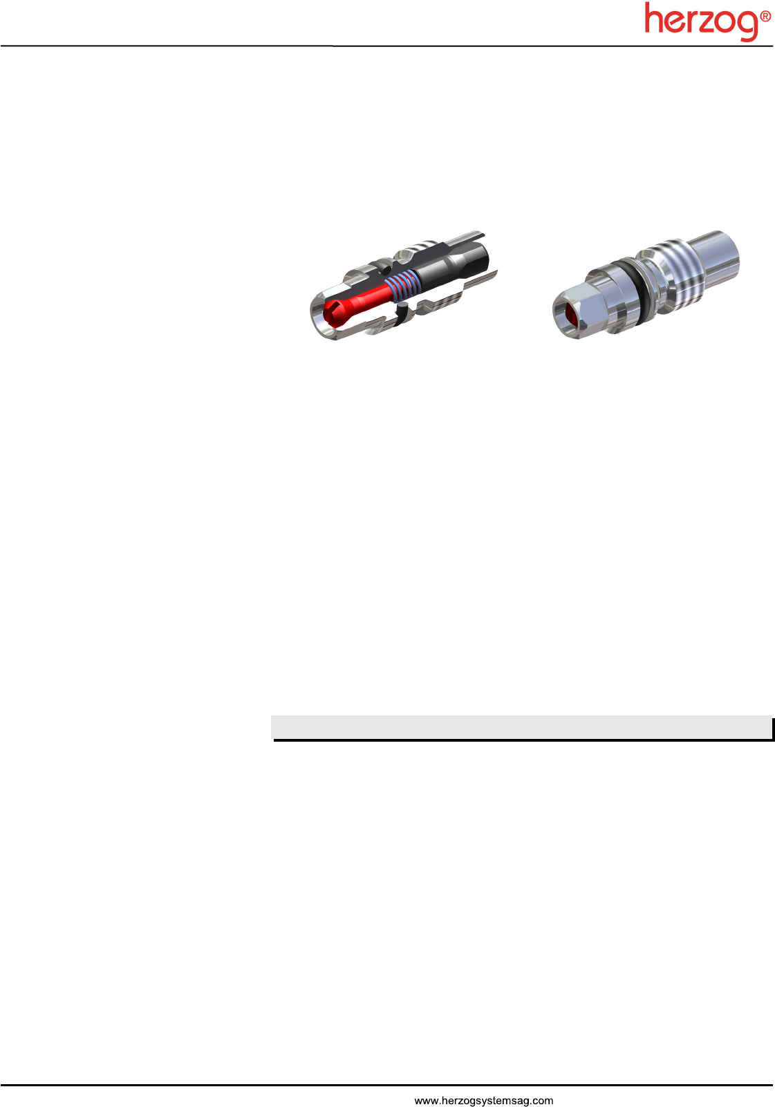
Mold-Injectors for Gas Assisted Injection Molding (GAIM)
Type GKR for back-gassing through the injector
Type GK without back-gassing
Applications:
In the mold, directly at the cavity
Characteristics:
Conical sealing injector based on the non-return / check valve principle
With or without back-gassing
Gassing with maximum flow rate
Index of contents
Chapter Page
Technical Description .................................................................................................. 2
Design and function of the injector ............................................................................. 2
Advantages of Herzog injectors .................................................................................. 2
Installation variation .................................................................................................... 3
Injector bore dimensions ............................................................................................ 4
GK & GKR service set instructions ............................................................................. 5
Dimension sheet for orders or enquiries ..................................................................... 6

GIT, mold injectors
herzog systems ag
Tel. +41 71 394 19 69
Fax. +41 71 394 19 60
info@herzogsystemsag.com
Seite 2 von 3
Version 06/2021
Technical description
Gas injection technology
With gas injection technology, gas is injected into the plastic melt usually at the end of the
injection process. The injected gas displaces the melt depending on the injector’s
location.
Short shot, cavity is partially filled with plastic melt. The plastic melt is pressed against
the mold wall with the injected fluid.
Full shot, entire cavity is filled with plastic melt. The injected fluid forces the melt into an
adjoining cavity.
Full shot back pressure procedure, entire cavity is filled with plastic melt. The injected
fluid forces the melt through the sprue bushing back into cylinder vestibule.
Advantages
Cycle time reduction
Contact force reduction
Increased part rigidity
Weight reduction
Remove part distortion
Improved surface quality
Eliminate sunken areas
Design and function of the injector
One or more injectors are installed directly in the mold, depending on the size and
geometry of the molded part as well as the viscosity of the melt.
The regulated gas, usually nitrogen, is fed through bores in the mold to the injector and
through this into the molded part. The back-gassing or gas pressure release goes
through the same injector (type GKR) back to the gas feed.
The gassing of the cavity is only possible when the gas injection pressure is higher than
the opposing pressure in the cavity. The gas injection pressure moves the pin which
opens the injector completely, allowing for high volumes to be achieved.
The back-gassing goes through cross-shaped surfaces on the sealing area of the pin.
The gap is large enough to allow the gas to flow through, but small enough to prevent the
melt from seeping in.
Maintenance of the injector can be carried out simply and quickly when the mold is open.
Advantages of Herzog injectors
Small dimensions
Back-gassing (gas pressure release) with type GKR
Ensures high process stability
Self cleaning function
Low maintenance
Assembly / disassembly at the mold interface level
Operating temperature range: -30°C to 180°C

GIT, mold injectors
herzog systems ag
Tel. +41 71 394 19 69
Fax. +41 71 394 19 60
info@herzogsystemsag.com
Seite 3 von 3
Version 06/2021
Interface block
Conduit
Mounting Injector
Cavity
P
Installation variation
Installed directly in the mold
The injector opening is directly in the mold.
Gassing occurs by means of drill holes in the mold plate.
Injector bore dimensions
P
Spacing tube
Locking nut
ø6 H6
Fit length 4
0,4
5
10,5 / M6
12,5 / ø5
5
max. ø3,5
90°
Insert - sealing
10
Using a mounting and conduit
The injector opening is in a mounting which is allowed into the mold.
A conduit runs from the injector mounting through the mold to the interface block.
Upgrading from GB to GK(R) type injectors
Existing GB injector bore may need to be re-worked according to the above drawing in
order to fit the GK(R) injector correctly. Please pay special attention to the bevelled edge
and the insert sealing.

GIT, mold injectors
herzog systems ag
Tel. +41 71 394 19 69
Fax. +41 71 394 19 60
info@herzogsystemsag.com
Seite 4 von 3
Version 06/2021
Torque wrench adjusting
Install / remove injector
Assembly / disassembly
Cleaning the injector casing
GK & GKR service set instructions
Attention!
Counter tool must be fully
inserted into the pin slit.
Heat the injector to approx. 80°C
to make loosening easier.
1. Clean and degrease pin and thread
2. Apply only little glue (using a toothpick) to insert thread
3. Assembly injector. Excess glue collects inside the insert. Attention! Glue must not
run into the injector
4. Drying time: 6 hours
5. When disassembling: Heat the injector to approx. 80°C to make loosening easier
Screw retention (glueing)
0.4 Nm
2.0 Nm
Clockwise = tighten
Anticlockwise = loosen
Pin O-ring Injector casing Spring Insert
Cavity
Apply only little glue to thread!
1. 2.
2.0 Nm
Max. 0.4 Nm
1. 2. 3.
click
Detailed instructions in installation and servicing manual: Mold injector for Gas
Injection Technology (GIT) - Instructions - Service Set. See www.herzog-ag.com

GIT, mold injectors
herzog systems ag
Tel. +41 71 394 19 69
Fax. +41 71 394 19 60
info@herzogsystemsag.com
Seite 5 von 3
Version 06/2021
Dimension sheet for enquiry or order GIT mold injector GK & GKR
Note
Technical modifications reserved
We need additional information for requirements, which vary from our standard range e.g. drawing sample. Our customer services will
be pleased to help you
Standard dimensions / Characteristics
Installation thread M6
Injector opening in molded part Ø 4.6mm
Injector length from cavity 5mm or 10mm
Back-gassing through the injector (GKR) Standard
Operating temperature range -30°C to 180°C
Please indicate
Injector length from cavity in mm 5 10
Without back-gassing through the injector (GK)
*Service set GK & GKR
* We recommend using our specially designed tool for installation and cleaning
Service set
Injector M6, 5mm
Injector M6, 10mm
Company:
Contact person:
Street:
Tel.:
City / Zip:
Fax:
Land:
E-Mail:
Upgrading from GB to GK(R) type injectors
Min. 10 bar gas pressure is required to overcome the spring force and open the GK(R) injector
Gas flow rate of GK(R) must be regulated (max. throughput 12kg/h)
