
CONTEXT02B
INCREASE PRODUCTION • REDUCE MAINTENANCE • REDUCE DOWNTIME • REDUCE SCRAP
CONTINUOUS EXTRUSION
PROCESS IMPROVEMENTS
NEEDLE CYLINDERS
KNOCKOUT CYLINDERS
phdinc.com (800) 624-8511

www.phdinc.com
•
(800) 624-8511
2
CONTEXT02B
We understand
Focused on the specific needs of the plastic packaging industry,
PHD has worked with a wide range of continuous extrusion
OEMs and user accounts to produce a variety of improved
solutions for the industry.
Our components are the actuators of choice. Designed for long
life, PHD products keep your blow molding lines running while
increasing productivity and reducing downtime and scrap.
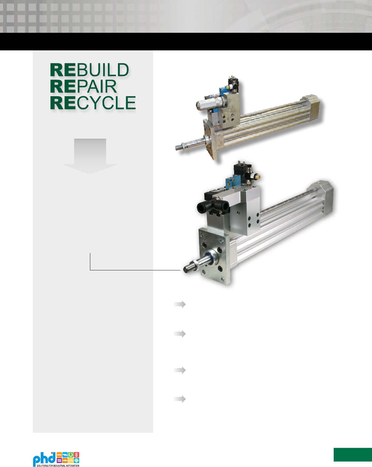
We also offer the added benefit of our rebuild program which
refurbishes your existing PHD components, enabling even
longer service life and savings.
© Copyright 2019, by PHD, Inc. All Rights Reserved. Printed in the U.S.A.
your unique
requirements
We offer a wide variety of direct replacement components.
Our drop-in components save you money by reducing costly
production downtime and maintenance costs.
Many of our components provide up to twice the life of the
original unit. This means longer run time for higher production
and higher profits.
With longer life,
reduced maintenance,
and reduced downtime
Easy Drop-in
Excellent delivery saves you money by getting you back to
business faster.
FASTER
delivery than
competitor
Superior Delivery
PHD offers a variety of components already designed
to fit unique requirements. If your application
requires a modified component from outside our
large database of designs, our team is ready to help.
We welcome special requests, regardless of quantity
or frequency of order. See page 14.
Special
Requirements
Unique Solutions
Our products can be rebuilt and put back in service
for continued savings. Plus you will receive a “like
new” warranty. See page 15 for more information.
Return
to Service
Rebuild Program
To request more literature, visit
www.phdinc.com/resources/inforequest/

www.phdinc.com
•
(800) 624-8511
3
CONTEXT02B
Any marks or names referenced herein are either registered trademarks or trademarks of their respective owners. No
association with or endorsement of any company, organization, or product is intended or should be inferred.
Replacement Reference Chart & Contents
NEEDLE CYLINDERS PAGE
Series BCT 4
Series BCN 11
Other Unique Solutions 14
KNOCKOUT CYLINDERS PAGE
Series CV Style 14
Series AV Style 14
Special Rod Style 14
ML304949
ML310701
ML306733

www.phdinc.com/bct
•
(800) 624-8511
4
CONTEXT02B
BCT
Needle Cylinder
Major Benefits
• Direct OEM solution used in continuous extrusion
wheels are available in three bore sizes and provide
superior blow pressure and exhaust
• Non-rotating shaft to keep needle tip in
correct orientation
• BCT2 (High Flow) version increases run time
between cleaning of “plate out” material
• Standard NPT ports for extend, retract and blow
• Internal shock pads standard on extend and retract
• Lubricated internally at factory for life of cylinder
using lubricant per FDA Regulation 21CFR 178.3570
• Option -H96 for mirrored porting and non-
rotating shaft, designed to help eliminate
machine interferences
• Cylinders are easily field repairable to maximize
your investment
Self-lubricating nitrile piston
seal provides long life
Non-rotating
hardened steel shaft
Rugged mechanically joined
piston and rod assembly
Self-lubricating nitrile rod
seals provide long life
Built-in shock pads are standard,
absorbing impact energy and
eliminating metal to metal contact
Hard chrome-plated steel
piston rods provide maximum
wear resistance for long life
Aluminum bushings
with PTFE filled hardcoat
provide maximum wear
resistance for long life
Standard NPT porting
for extend and retract
Clear anodized extruded body
NPT manifold
porting
Composite bushing
BCT1
(Manifold)
NPT end porting for
higher flow requirements
and increased time
interval between cleaning
BCT2
(High Flow)
BCT1 (Manifold)
BCT2 (High Flow)
BCT Needle
Cylinder
Continuous
Extrusion Wheel

www.phdinc.com/bct
•
(800) 624-8511
5
CONTEXT02B
ORDERING DATA: SERIES BCT NEEDLE CYLINDER
x
TO ORDER, SPECIFY:
Product Line, Series, Product Type, Build Type,
Design No., Bore Size, Stroke, Cylinder Options
NOTES:
1) Standard Needle Cylinder ordering number is as follows:
BCT1-1-50 x 35
2) -W1 option needs to be specified for flange to be attached to unit
-
1C 32T
H96
OPTIONS
W1
-
Attached Flange - 2.0 x 2.0 Square Mount Pattern
(for Ø 32 and Ø 50 only)
H96
-
Mirror Port and Non-Rotating Shaft
25
PRODUCT LINE
B - Blow Molding
B
SERIES
C - Cylinder
1
DESIGN NO.
1 - Imperial
BORE SIZE (mm)
32
40
50
--
BUILD TYPE
1 - Standard-Manifold
2 - High Flow
STROKE
Contact PHD for other strokes
STANDARD STROKE (mm)
25
20, 40
35
BORE
32
40
50
PRODUCT TYPE
T - Compact
Non-Rotating
SPECIFICATIONS SERIES BCT
OPERATING PRESSURE 20 psi min to 150 psi max at zero load [1.4 bar min to 10 bar max] air
STROKE TOLERANCE ±0.031 in [0.8 mm]
TEMPERATURE LIMITS -20 to +180°F [-28 to +82°C]
VELOCITY 20 in/sec [0.5 m/sec] typical min, zero load at 100 psi [7 bar]
LIFE EXPECTANCY 30 million linear inches [762000 linear meters] min
LUBRICATION Lubrication per FDA Regulation 21CFR 178.3570
MAINTENANCE Field repairable
CYLINDER FORCE AND WEIGHT
BORE
ROD
DIRECTION
OUTLET ROD DIAMETER EFFECTIVE AREA BCT1 BASE WEIGHT BCT2 BASE WEIGHT ADDER PER 5 mm OF STROKE
mm in in mm in² mm² lb kg lb kg lb kg
32 1.260
Extend 0.750 19.1 0.805 519
0.62 0.23 0.59 0.22 0.07 0.03
Retract 0.625 15.9 0.904 583
40 1.575
Extend 0.750 19.1 1.506 972
0.69 0.26 0.64 0.24 0.13 0.05
Retract 0.625 15.9 1.641 1059
50 1.969
Extend 0.750 19.1 2.603 1679
1.03 0.38 0.97 0.36 0.10 0.04
Retract 0.750 19.1 2.603 1679
CYLINDER FORCE CALCULATIONS
Imperial Metric
F = P x A F = 0.1 x P x A
F = Cylinder Force lbs N
P = Operating Pressure psi bar
A = Effective Area
(Extend or Retract)
in
2
mm
2
ENGINEERING DATA: SERIES BCT NEEDLE CYLINDER
www.phdinc.com/bct
•
(800) 624-8511
6
CONTEXT02B
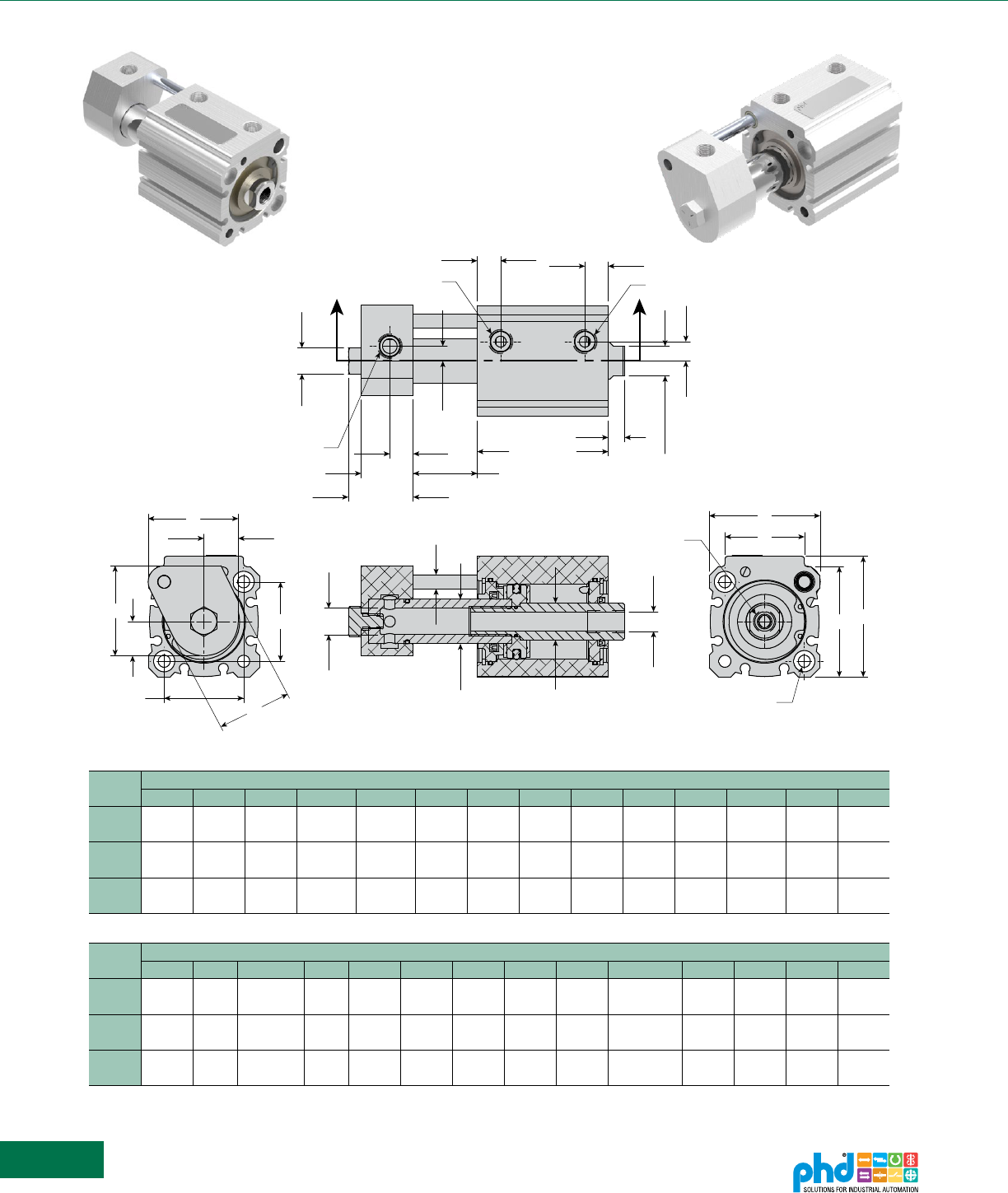
DIMENSIONS: SERIES BCT1 NEEDLE CYLINDER
BORE
DIMENSIONS
A B C D1 D2 E F G H J K K1 L M
32
1.519 0.579 1.250 0.750 0.625 1.870 1.339 0.437 0.330 1.224 0.394 0.250 0.394 0.394
[38.6] [14.7] [31.8] [19.1] [15.9] [47.5] [34.0] [11.1] [8.4] [31.1] [10.0] [6.4] [10.0] [10.0]
40
1.699 0.600 1.250 0.750 0.625 2.205 1.574 0.437 0.330 1.148 0.394 0.349 0.394 0.394
[43.2] [15.2] [31.8] [19.1] [15.9] [56.0] [40.0] [11.1] [8.4] [29.2] [10.0] [8.9] [10.0] [10.0]
50
1.876 0.626 1.250 0.750 0.750 2.598 1.968 0.437 0.330 1.292 0.394 0.438 0.470 0.470
[47.7] [15.9] [31.8] [19.1] [19.1] [66.0] [50.0] [11.1] [8.4] [32.8] [10.0] [11.1] [11.9] [11.9]
BORE
DIMENSIONS
N P R THREAD S T U V W Y Z THREAD AA BB CC DD
32 1/8 NPT
0.326
1/4 NPT 10-24
0.394 0.276 0.500 2.037 1.340
3/8-24 x
0.625
0.236 0.875 0.098 1.094
[8.3] [10.0] [7.0] [12.7] [51.7] [34.0] [6.0] [22.2] [2.5] [27.8]
40 1/8 NPT
0.365
1/4 NPT 10-24
0.394 0.276 0.500 2.363 1.420
3/8-24 x
0.625
0.236 0.875 0.175 1.094
[9.3] [10.0] [7.0] [12.7] [60.0] [36.1] [6.0] [22.2] [4.4] [27.8]
50 1/4 NPT
0.476
1/4 NPT 1/4-20
0.394 0.315 0.625 2.795 1.600
1/2-20 x
0.750
0.236 0.875 0.108 1.094
[12.1] [10.0] [8.0] [15.9] [71.0] [40.6] [6.0] [22.2] [2.7] [27.8]
DIMENSIONS IN [ ] ARE mm
A
A
B
B
F
F
C
R PORT (BLOW)
N PORT (RETRACT)
N PORT (EXTEND)
M
L
J + STROKE
CC + STROKE
K
U
BB
T WRENCH FLAT
V WRENCH FLAT
0.189 [4.8] LONG
P
K1
DD
Z THREAD
Y
E
W
E
2X THRU & C BORE FOR S
SOCKET HEAD CAP SCREW
(BOTH ENDS)
Ø AA
Ø D1
Ø D2
Ø HØ G
All dimensions are reference only unless specifically toleranced.

www.phdinc.com/bct
•
(800) 624-8511
7
CONTEXT02B
DIMENSIONS: SERIES BCT2 NEEDLE CYLINDER
BORE
DIMENSIONS
A B C D1 D2 E F G H J K L M
32
1.856 0.751 1.250 0.750 0.625 1.870 1.339 0.437 0.330 1.224 0.375 0.394 0.394
[47.1] [19.1] [31.8] [19.1] [15.9] [47.5] [34.0] [11.1] [8.4] [31.1] [9.5] [10.0] [10.0]
40
1.856 0.751 1.250 0.750 0.625 2.205 1.574 0.437 0.330 1.148 0.375 0.394 0.394
[47.1] [19.1] [31.8] [19.1] [15.9] [56.0] [40.0] [11.1] [8.4] [29.2] [9.5] [10.0] [10.0]
50
2.036 0.666 1.250 0.750 0.750 2.598 1.968 0.437 0.330 1.292 0.375 0.470 0.470
[51.7] [16.9] [31.8] [19.1] [19.1] [66.0] [50.0] [11.1] [8.4] [32.8] [9.5] [11.9] [11.9]
BORE
DIMENSIONS
N P R THREAD S T U V W Y Z THREAD AA BB CC
32 1/8 NPT
0.326
1/4 NPT 10-24
0.632 0.276 0.500 2.037 1.340
3/8-24 x 0.625
0.236 0.702 0.098
[8.3] [16.1] [7.0] [12.7] [51.7] [34.0] [6.0] [17.8] [2.5]
40 1/8 NPT
0.326
1/4 NPT 10-24
0.632 0.276 0.500 2.363 1.420
3/8-24 x 0.625
0.236 0.702 0.098
[8.3] [16.1] [7.0] [12.7] [60.0] [36.1] [6.0] [17.8] [2.5]
50 1/4 NPT
0.476
1/4 NPT 1/4-20
0.632 0.315 0.625 2.795 1.600
1/2-20 x 0.750
0.236 0.702 0.067
[12.1] [16.1] [8.0] [15.9] [71.0] [40.6] [6.0] [17.8] [1.7]
DIMENSIONS IN [ ] ARE mm
R PORT (BLOW)
Ø AA
Ø D1 Ø D2
Ø HØ G
A
A
B
B
F
C
F
Z THREAD
Y
E
W
E
2X THRU & C BORE FOR S
SOCKET HEAD CAP SCREW
(BOTH ENDS)
N PORT (RETRACT)
N PORT (EXTEND)
M
L
J + STROKE
CC + STROKE
K
U
BB
T WRENCH FLAT
0.219 [5.6] LONG
V WRENCH FLAT
0.189 [4.8] LONG
P
All dimensions are reference only unless specifically toleranced.

www.phdinc.com/bct
•
(800) 624-8511
8
CONTEXT02B
OPTIONS: SERIES BCT NEEDLE CYLINDER
This option attaches a mount plate with a 2" x 2" mounting hole pattern to
the cylinder and includes all fasteners. For Ø 32 and Ø 50 bore sizes only.
ATTACHED MOUNTING FLANGE
OPTION 2" x 2" HOLE PATTERN
W1
DIMENSIONS IN [ ] ARE mm
4X Ø L
A
D
Ø C
B
A
B
D
A
Ø C
B
A
B
Ø C
B
B
A
A
D
G
F
E
2X H THD
E
F
G
K
J
G
F
E
2X H THD
J
K
BCTx-1-32
4X Ø L
A
D
Ø C
B
A
B
D
A
Ø C
B
A
B
Ø C
B
B
A
A
D
G
F
E
2X H THD
E
F
G
K
J
G
F
E
2X H THD
J
K
BCTx-1-50
All dimensions are reference only unless specifically toleranced.
BORE
DIMENSIONS
A B C D E F G H THD J K L
32
2.500 2.000 1.247 0.375 0.224 0.125 0.375 — — — 0.281
[63.5] [50.8] [31.7] [9.5] [5.7] [3.2] [9.5] — — — [7.1]
50
2.750 2.000 1.247 0.375 0.375 0.125 1.562 1/4-20 1.625 0.338 —
[69.9] [50.8] [31.7] [9.5] [9.5] [3.2] [39.7] 1/4-20 [41.3] [8.6] —

www.phdinc.com/bct
•
(800) 624-8511
9
CONTEXT02B
NON-ROTATING SHAFT
EXTEND PORT
RETRACT PORT
BLOW PORT
K1
EE
P
NON-ROTATING SHAFT AND PORTS
MIRRORED OVER CENTERLINE OF CYLINDER
NON-ROTATING SHAFT
RETRACT PORT
EXTEND PORT
BLOW PORT
K1
P
EE
OPTIONS: SERIES BCT NEEDLE CYLINDER
This option mirrors the ports and non-rotating shaft over the centerline of
the cylinder to allow for additional machine clearance in some instances.
MIRROR PORT AND
NON-ROTATING SHAFT OPTION
H96
BORE
DIMENSIONS
K1 P EE
32 0.250 [6.4] 0.326 [8.3] 0.579 [14.7]
40 0.349 [8.9] 0.365 [9.3] 0.600 [15.2]
50 0.438 [11.1] 0.476 [12.1] 0.626 [15.9]
DIMENSIONS IN [ ] ARE mm
BORE
DIMENSIONS
P EE
32 0.326 [8.3] 0.579 [14.7]
40 0.365 [9.3] 0.600 [15.2]
50 0.476 [12.1] 0.626 [15.9]
DIMENSIONS IN [ ] ARE mm
BCT1
STANDARD UNIT
BCT2
STANDARD UNIT
BCT1
-H96 OPTION
BCT2
-H96 OPTION
All dimensions are reference only unless specifically toleranced.
NON-ROTATING SHAFT
EXTEND PORT
RETRACT PORT
BLOW PORT
EE
P
NON-ROTATING SHAFT AND PORTS
MIRRORED OVER CENTERLINE OF CYLINDER
NON-ROTATING SHAFT
RETRACT PORT
EXTEND PORT
BLOW PORT
P
EE

www.phdinc.com/bct
•
(800) 624-8511
10
CONTEXT02B
PARTS LIST & REPAIR KITS: SERIES BCT NEEDLE CYLINDER
KIT DESCRIPTION KIT NUMBER COLOR CODE*
Seal Kit Full unit description and -H9000
Repair Kit Full unit description and -H9010
* Color code designates parts to be included in kit
32 mm Bore Flange Kit
KIT DESCRIPTION KIT NUMBER COLOR CODE*
-W1 Option Full unit description and -H2000
* Color code designates parts to be included in kit
50 mm Bore Flange Kit
KIT DESCRIPTION KIT NUMBER COLOR CODE*
-W1 Option Full unit description and -H2000
* Color code designates parts to be included in kit
KEY PART DESCRIPTION 32 mm 40 mm 50 mm
1 Body Assembly Full unit description and -H2400
2 Outlet Rod Bushing 74049 73872 73873
3 Inlet Rod Bushing 88457 88519 73873
4 O-Ring Seal 3642-027-1 3642-028-1 3642-029-1
5 Outlet Rod Seal 18521-016 18521-016 18521-007
6 Inlet Rod Seal 18521-007 18521-007 18521-007
7 Retaining Ring 1987-073 1987-079 1987-085
8 Piston and Rod Assembly Full unit description and -H1000
9 Manifold Full unit description and -H6400
10 O-Ring Seal 1950-016-1 1950-016-1 1950-016-1
11 Hex Head Bolt 57021-025 57021-025 57021-025
12 Piston Seal 74042-008 74042-009 74042-010
13 Outlet Shock Pad 74029 74029 74030
14 Inlet Shock Pad 88452 88452 74030
15 Non-Rotating Shaft 17831-102 17831-102 17831-102
16 Non-Rotating Plate 88458 86738 86739
17 Nut 3204-084 3204-084 3204-084
18 Flange Sold as part of Flange Kit
19 Cylinder to Flange SHCS Sold as part of Flange Kit
20 Flange Mounting SHCS Sold as part of Flange Kit
1
13
8
BCT1 UNITS
14
11
9
15
BCT1 UNITS
BCT1 UNITS
BCT1 UNITS
17
15
16
BCT2 UNITS
BCT2 UNITS
8
BCT2 UNITS
-W1 OPTION
-W1 OPTION
-W1 OPTION
-W1 OPTION
-W1 OPTION
4
10
12
4
6
3
7
2
5
7
18
19
19
20
20
= LOCTITE 242 THREAD LOCKER
= LOCTITE R/C 680
= LUBRICANT PER FDA
REGULATION 21CFR 178.3570
BORE
ID
ID

www.phdinc.com/bcn
•
(800) 624-8511
11
CONTEXT02B
Needle Cylinder Replacement
Major Benefits
• Direct replacement for continuous extrusion blow molding
needle cylinders.
• Provides significantly longer life and reduces maintenance
and downtime.
• Internal needle orientation stud provides anti-rotational
movement and allows the needle to be infinitely adjustable
without increasing package length.
• Unique modular design provides a variety of design
configurations without sacrificing delivery and price.
• Male rod ends have piloted ends to reduce concentricity
issues with attached needles.
• Consult PHD for other custom needle cylinders and blow
molding actuators to meet your automation requirements.
3 port cylinder shown,
Consult PHD for 2 port
polyurethane lip seals
provide long life and
easy replacement
carbon-filled teflon composite
wear ring supports piston and
protects piston seals
stainless steel anti-rotational
stud provides adjustable
needle orientation
internal lubrication reservoir
with food grade lubricant
increases cylinder life
shock pads on extend and
retract reduce impact force
and increase cylinder life
engineered polymer
bushing is easy to replace
deep exhaust
channels increase
exhaust flow
optional mounting flanges
optional rod ends increase flow
rates and allow for easy and
precise needle attachment
BCN
Needle Cylinder

www.phdinc.com/bcn
•
(800) 624-8511
12
CONTEXT02B
1T13305825 25 TMO26x -ML --
TO ORDER SPECIFY:
ML#, Port Configuration,
Mounting Style, Design No.,
Bore Size, Stroke, and Options.
MOUNTING STYLE
N - Nose Mount
T1 - Flange Style 1
U - Universal Mount
DESIGN NO.
1 - Imperial
5 - Metric
STROKE
19 - 19 mm (0.748 in)
26 - 26 mm (1.024 in)
BORE SIZE
25 mm
PORT CONFIGURATION
3 - 3 Port, 12 mm Rod
5 - 3 Port, 10 mm Rod
Consult PHD for 2 Port units
OPTIONS
T30 - Female Rod End
TMO - Male Rod End - High Flow
Extended thread length
TRO - Oversize Female Rod End
Other configurations are available. Contact PHD for options.
ORDERING DATA: SERIES BCN NEEDLE CYLINDER
ENGINEERING DATA: SERIES BCN NEEDLE CYLINDER
SPECIFICATIONS IMPERIAL (1) METRIC (5)
TYPE Blow Mold Needle Cylinder
SERIES BCN
BORE SIZE 0.984 in 25 mm
BORE AREA 0.761 in² 4.91 cm²
THEORETICAL OUTPUT 66.2 lb @ 87 psi 294.5 N @ 6 bar
OPERATION Double Acting
OPERATING PRESSURE RANGE 7.5 - 150 psi 0.5 - 10 bar
AMBIENT TEMPERATURE -18.4° to 176° F -28° to 80° C
LUBRICATION; FOOD GRADE FDA Regulation 21CFR 178.3570
PORT SIZE 1/8 NPT [1/8 BSPP]
STROKE TOLERANCE +0.059/-0.000 +1.5/-0.000
WEIGHT @ 25 mm STROKE 1.1 lb 0.50 kg
BUMPERS Polyurethane, Extend, and Retract
HEAD Anodized Aluminum
CYLINDER BODY Anodized Aluminum
PISTON ROD Chrome Plated Stainless Steel
ROD BEARING Engineered Polymer
PISTON & ROD SEALS Polyurethane
PISTON Hardcoated PTFE Aluminum

www.phdinc.com/bcn
•
(800) 624-8511
13
CONTEXT02B
3 PORT CONFIGURATION
2X M4 x 0.7 x 0.472 DP
5/16-24 THD (DESIGN 1)
M8 x 1.25 THD (DESIGN 5)
3X 1/8 NPT (DESIGN 1)
3X BSPP PORT (DESIGN 5)
BLOW PORT
11 mm WRENCH FLAT
ROD END TO ACCEPT
5/32 NEEDLE
1.407
[35.7]
EXTENDED
0.341
[8.7]
D
C
B
A
0.843
[21.4]
0.863
[21.9]
1.250
[31.8]
0.122
[3.1]
0.125
[3.2]
1.614
[41]
0.750
[19.1]
0.159
[4]
0.141
[3.6]
0.317 0.001
[8.052
0.025]
2X .375
[9.5]
Ø .998
[25.3]
4X Ø .281
[7.1]
1.250
[31.8]
2X .325
[8.3]
.114
[2.9]
2X .189
[4.8]
.100
[2.5]
.125
[3.2]
.375
[9.5]
T1 Mounting Style
T2 Mounting Style
1.500
[38.1]
1.930
[49]
1.500
[38.1]
1.930
[49]
62
ϒ
2X .375
[9.5]
Ø 1.250
[31.8]
Ø
.998
[25.3]
3X Ø .281
[7.1]
1.398
[35.5]
2X 45
ϒ
6X .325
[8.3]
6X .114
[2.9]
6X .189
[4.8]
.100
[2.5]
.125
[3.2]
.375
[9.5]
T3 Mountng Style N Mounting Style
2.500
[63.5]
2.000
[50.8]
2X .375
[9.5]
Ø 1.247
[31.7]
1.250
[31.8]
4X
Ø .281
[7.1]
.375
[9.5]
.125
[3.2]
.100
[2.5]
2X .189
[4.8]
2X .114
[2.9]
.325
[8.3]
1.250
[31.8]
Ø 1.614
[41]
.375
[9.5]
2X .114
[2.9]
2X .189
[4.8]
2X .325
[8.3]
Ø .871
[22.1]
.125
[3.2]
.750
[19.1]
Ø .6251
[15.9]
2X .375
[9.5]
Ø
.998
[25.3]
4X Ø .281
[7.1]
1.250
[31.8]
2X .325
[8.3]
.114
[2.9]
2X .189
[4.8]
.100
[2.5]
.125
[3.2]
.375
[9.5]
T1 Mounting Style
T2 Mounting Style
1.500
[38.1]
1.930
[49]
1.500
[38.1]
1.930
[49]
62ϒ
2X .375
[9.5]
Ø
1.250
[31.8]
Ø
.998
[25.3]
3X
Ø
.281
[7.1]
1.398
[35.5]
2X 45
ϒ
6X .325
[8.3]
6X .114
[2.9]
6X .189
[4.8]
.100
[2.5]
.125
[3.2]
.375
[9.5]
T3 Mountng Style N Mounting Style
2.500
[63.5]
2.000
[50.8]
2X .375
[9.5]
Ø 1.247
[31.7]
1.250
[31.8]
4X
Ø .281
[7.1]
.375
[9.5]
.125
[3.2]
.100
[2.5]
2X .189
[4.8]
2X .114
[2.9]
.325
[8.3]
1.250
[31.8]
Ø
1.614
[41]
.375
[9.5]
2X .114
[2.9]
2X .189
[4.8]
2X .325
[8.3]
Ø .871
[22.1]
.125
[3.2]
.750
[19.1]
Ø .6251
[15.9]
DIMENSIONS: SERIES BCN NEEDLE CYLINDER
CONFIGURATION STROKE Ø A B C D
3
19, 26, 30 0.472 [12] 4.632 [118] 4.160 [106] 1.501 [38]
35, 39 0.472 [12] 5.537 [141] 5.065 [129] 2.052 [52]
5
19, 26, 30 0.394 [10] 4.632 [118] 4.160 [106] 1.501 [38]
35, 39 0.394 [10] 5.537 [141] 5.065 [129] 2.052 [52]
B THREAD X C DP MIN
D
A
B THREAD x C DP MIN.
D
A
TR0 - Oversize
Female Rod End
T30 - Female Rod End TM0 - High Flow
Male Rod End
0.190
[4.8]
5/16-24 THD (DESIGN 1)
M8 x 1.25 THD (DESIGN 5)
0.172
[4.4]
ROD END TO ACCEPT
3/16 NEEDLE
0.843
[21.4]
0.750
[19.1]
CONFIGURATION Ø A B C D
3
0.472 3/8-24 0.687 1.507
[12] [M10 x 1.5] [17.4] [38.3]
5
0.394 5/16-24 4.160 1.407
[10] [M8 x 1.0] [105.7] [35.7]
CONFIGURATION Ø A B C D
3
0.472 5/16-24 0.687 1.407
[12] [M8 x 1.0] [17.4] [35.7]
All dimensions are reference only unless specifically toleranced.

www.phdinc.com
•
(800) 624-8511
14
CONTEXT02B
KNOCKOUT
NEEDLE
OTHER NEEDLE & KNOCKOUT CYLINDERS
ML304949
ML310701
ML306733
More needle & knockout
actuators are available.
PHD has designed direct replacements for various continuous
extrusion blow molding needle and knockout cylinders.
In addition, PHD offers the service of our Unlimited Unique Solutions
group. With Unique Solutions, we have the ability to design specific
needle and knockout cylinder replacements that will fit your particular
machine. Benefits include significantly longer life and reduced
maintenance and downtime. PHD unique modular designs provide a
variety of configurations without sacrificing delivery or price.
PHD needle cylinders offer an internal needle orientation stud which
provides anti-rotational movement and allows the needle to be
infinitely adjustable without increasing package length.
Male rod ends have piloted ends to reduce concentricity issues with
attached needles.
Optimized mold-mounted knockout cylinder designs meet your unique
needs while eliminating mechanical or machine mounted knockouts,
thus improving the process and product consistency.
Contact PHD for more needle and knockout
cylinder solutions.
• Most quotes delivered within eight working hours
• Dedicated application assistance
• 24 hours a day, 7 days a week service
• Fast delivery and competitive pricing
• CAD files available prior to ordering
• Geared towards short-run requests
• All units receive an “ML” number when
ordered. This number, along with all
specifications, is kept on permanent
record at PHD for future reference
and reorders.
PHD Series CV Style
PHD Series AV Style
UNIQUE SOLUTIONS
®
To request a free brochure, visit
www.phdinc.com/resources/inforequest/
Special Rod Style
www.phdinc.com
•
(800) 624-8511
15
CONTEXT02B
Rebuild Program
Plastic Packaging Components such
as Stretching Cylinders, Transfer
Arms, Blow Nozzles, Filler Cylinders,
Slip Sheet Grippers, and Eject Slides
are rebuildable.
Get a 12 Month
“Like New”
Warranty
PHD’s rebuild program can save
your facility training, additional work
load, possible tool requirements,
and facility space to perform the
rebuilds. In addition, you will receive
a 12 month “like new” warranty.
REBUILD IT
YOURSELF OR
ALLOW PHD?
PHD’s Rebuild Program refurbishes
your existing PHD products with all
new wear items.
Rebuilt units offer the same PHD quality
that you’re used to, but for a fraction
of the cost of a new unit, reducing your
total cost of ownership.
Rebuilt units are placed back into service,
thus reducing your total cost and saving
valuable components from scrap.
All PHD factory rebuilt units receive a
12 month “like new” warranty.
Return your old
units for rebuilding
Before:
After: This stretching
cylinder was rebuilt and
returned to service.

www.phdinc.com
•
(800) 624-8511
16
CONTEXT02B
BCK Stretching
Cylinders
‘K’ Style spare components
Simplied pneumatic system
Eject Cylinders
ML309880 and ML310656
‘K’ Style spare components
Provides rapid repeatable ejection
function due to MAC valve design
and PHD cylinder.
High kinetic energy capacity
Provides faster delivery times than
OEM product
In many cases lower cost solution
than OEM product
Intended for high speed
part rejection
Transfer Arm Head
ML311628
‘K’ Style spare component
‘K’ STYLE
‘S’ STYLE
Slip Sheet Gripper
Modular assembly consisting of
a clamp, slide, and transition plate
Clamp provides a wide opening
so slip sheets are not missed
Quick installation and
easy maintenance
Fill Line Eject Slide
ML309590
Repeatable ejection
High kinetic energy capacity
Uses proven PHD thruster
slide technology
Cam Follower
Wheels
Competitive pricing
Longer life than OEM
Available in variety of material
BCS Stretching
Cylinders
‘S’ Style Series1, Series2, and
Universal spare components
X27 PHD check valve option
BCZ Nozzle
Cylinders
‘S’ Style Series2 and Universal
spare components
Valve manifold assembled
to cylinder available as standard
BST Transfer Arm Preferential Head
BST1
Transfer Arm
‘S’ Style Series1 spare component
Signicantly more robust and
precise than other transfer arms
Designed to operate over
20 million cycles
BST2
Transfer Arm
‘S’ Style Series2 spare component
Vertical height adjustment
eliminates need for shims
Designed to operate over
20 million cycles
Preform/
Bottle Eject Slide
‘S’ Style Series2 spare component
Consistent preform/bottle ejection
Minimizes stress on
transfer arm jaws
To request more literature, visit
www.phdinc.com/resources/inforequest/
OTHER SOLUTIONS
6/19 10959
