
World Headquarters
Victrex plc
Victrex Technology Centre
Hillhouse International
Thornton Cleveleys
Lancashire FY5 4QD
United Kingdom
Tel: +44 (0) 1253 897700
Fax: +44 (0) 1253 897701
Email: [email protected]
Americas
Victrex USA Inc.
3A Caledon Court
Greenville, SC 29615
USA
Tel: + (1) 800 VICTREX
Tel: + (1) 864 672 7335
Fax: + (1) 864 672 7328
Email: [email protected]
Europe
Victrex Europa GmbH
Hauptstr. 11
65719 Hofheim/Ts.
Germany
Tel: + (49) 6192 964949
Fax: + (49) 6192 964948
Email: [email protected]
Asia-Pacific
Victrex plc
Hanai Building 6F
1-2-9 Shiba Koen
Minato-Ku
Tokyo 105 -0011
Japan
Tel: +(81) 35777 8737
Fax: +(81) 35777 8738
Email: [email protected]
Victrex plc believes that the information contained in this brochure is an accurate description of the typical characteristics and/or uses of the product or
products, but it is the customer's responsibility to thoroughly test the product in his specific application to determine its performance, efficacy and safety
for each end-use product, device or other application. Suggestions of uses should not be taken as inducements to infringe any particular patent. The
information and data contained herein are based on information we believe reliable. Mention of a product in this documentation is not a guarantee of
availability. Victrex plc reserves the right to modify products, specifications and/or packaging as part of a continuous program of product development.
©Victrex USA 604/1.5M
▲ World Headquarters
▲ Sales Offices
Distributors
www.victrex.com
A Global Company
Victrex plc is an innovative world-leader in high performance materials.
It has manufacturing plants and research facilities in the UK, and sales
and distribution centers serving more than 30 countries worldwide
▲
▲
▲HQ
▲
▲
▲
▲
▲
▲
▲
▲
▲
▲
▲
▲
▲▲
▲
▲
▲
▲
▲
▲

A comprehensive review of the processing
guidelines of VICTREX
®
PEEK
™
high performance polymer
PROCESSING GUIDE

www.victrex.com

1
TABLE OF CONTENTS
Page
INTRODUCTION
Process Preparation and Handling of VICTREX PEEK . . . . . . . . . . . . . . . . . . .3
Drying . . . . . . . . . . . . . . . . . . . . . . . . . . . . . . . . . . . . . . . . . . . . . . . . . . . . . . . . .3
Re-Work . . . . . . . . . . . . . . . . . . . . . . . . . . . . . . . . . . . . . . . . . . . . . . . . . . . . . . . .3
Thermal Stability . . . . . . . . . . . . . . . . . . . . . . . . . . . . . . . . . . . . . . . . . . . . . . . . .3
Processability . . . . . . . . . . . . . . . . . . . . . . . . . . . . . . . . . . . . . . . . . . . . . . . . . . . .3
Purging Injection Molders and Extruders . . . . . . . . . . . . . . . . . . . . . . . . . . . . .4
An Overview of Start-Up Purging . . . . . . . . . . . . . . . . . . . . . . . . . . . . . . . . . . .4
An Overview of Shut-Down Purging . . . . . . . . . . . . . . . . . . . . . . . . . . . . . . . . .4
Materials of Construction for VICTREX PEEK Processing Equipment . . . . . . .5
INJECTION MOLDING
Machine Design . . . . . . . . . . . . . . . . . . . . . . . . . . . . . . . . . . . . . . . . . . . . . . . . . .5
Barrel Temperatures . . . . . . . . . . . . . . . . . . . . . . . . . . . . . . . . . . . . . . . . . . . . . .5
Barrel Capacity . . . . . . . . . . . . . . . . . . . . . . . . . . . . . . . . . . . . . . . . . . . . . . . . . .5
Nozzles and Shut-Off Systems . . . . . . . . . . . . . . . . . . . . . . . . . . . . . . . . . . . . . .5
Injection and Clamping Pressures . . . . . . . . . . . . . . . . . . . . . . . . . . . . . . . . . . .5
Screw Design . . . . . . . . . . . . . . . . . . . . . . . . . . . . . . . . . . . . . . . . . . . . . . . . . . . .6
Mold Design . . . . . . . . . . . . . . . . . . . . . . . . . . . . . . . . . . . . . . . . . . . . . . . . . . . .6
Mold Temperature . . . . . . . . . . . . . . . . . . . . . . . . . . . . . . . . . . . . . . . . . . . . . . .6
Melt Flow . . . . . . . . . . . . . . . . . . . . . . . . . . . . . . . . . . . . . . . . . . . . . . . . . . . . . . .6
Gating . . . . . . . . . . . . . . . . . . . . . . . . . . . . . . . . . . . . . . . . . . . . . . . . . . . . . . . . .7
Hot Runner Systems . . . . . . . . . . . . . . . . . . . . . . . . . . . . . . . . . . . . . . . . . . . . . .7
Shrinkage and Tolerances . . . . . . . . . . . . . . . . . . . . . . . . . . . . . . . . . . . . . . . . . .7
Operating Conditions . . . . . . . . . . . . . . . . . . . . . . . . . . . . . . . . . . . . . . . . . . . . .8
Injection Pressures and Screw Speed . . . . . . . . . . . . . . . . . . . . . . . . . . . . . . . . .9
Troubleshooting . . . . . . . . . . . . . . . . . . . . . . . . . . . . . . . . . . . . . . . . . . . . . . . . .9
EXTRUSION
Machine Design . . . . . . . . . . . . . . . . . . . . . . . . . . . . . . . . . . . . . . . . . . . . . . . . .11
Barrel Temperatures . . . . . . . . . . . . . . . . . . . . . . . . . . . . . . . . . . . . . . . . . . . . .11
Barrel Capacity and Residence Time . . . . . . . . . . . . . . . . . . . . . . . . . . . . . . . .11
Screw Design . . . . . . . . . . . . . . . . . . . . . . . . . . . . . . . . . . . . . . . . . . . . . . . . . . .11
Wire and Cable Coating . . . . . . . . . . . . . . . . . . . . . . . . . . . . . . . . . . . . . . . . . .11
Die and Crosshead Design . . . . . . . . . . . . . . . . . . . . . . . . . . . . . . . . . . . . . . . .11
Wire and Cable Crystallinity . . . . . . . . . . . . . . . . . . . . . . . . . . . . . . . . . . . . . . .11
Extruder Size and Control . . . . . . . . . . . . . . . . . . . . . . . . . . . . . . . . . . . . . . . .11
Sheet Manufacture . . . . . . . . . . . . . . . . . . . . . . . . . . . . . . . . . . . . . . . . . . . . . .12
Die Design . . . . . . . . . . . . . . . . . . . . . . . . . . . . . . . . . . . . . . . . . . . . . . . . . . . . .12
Thin Film and Sheet Crystallinity . . . . . . . . . . . . . . . . . . . . . . . . . . . . . . . . . . .12
Monofilament . . . . . . . . . . . . . . . . . . . . . . . . . . . . . . . . . . . . . . . . . . . . . . . . . .12
Monofilament Orientation . . . . . . . . . . . . . . . . . . . . . . . . . . . . . . . . . . . . . . . .13
COMPRESSION MOLDING
Basic Process . . . . . . . . . . . . . . . . . . . . . . . . . . . . . . . . . . . . . . . . . . . . . . . . . . .14
Equipment Requirements . . . . . . . . . . . . . . . . . . . . . . . . . . . . . . . . . . . . . . . . .14
Compression Molding Characteristics . . . . . . . . . . . . . . . . . . . . . . . . . . . . . . .14

2
Page
POWDER COATING
Electrostatic Spray and Fluidized Bed Coating . . . . . . . . . . . . . . . . . . . . . . . . .15
Dispersion Spray Coating . . . . . . . . . . . . . . . . . . . . . . . . . . . . . . . . . . . . . . . . . .15
FINISHING OPERATIONS
Machining . . . . . . . . . . . . . . . . . . . . . . . . . . . . . . . . . . . . . . . . . . . . . . . . . . . . . .15
Prototype Performance . . . . . . . . . . . . . . . . . . . . . . . . . . . . . . . . . . . . . . . . . . .15
Annealing . . . . . . . . . . . . . . . . . . . . . . . . . . . . . . . . . . . . . . . . . . . . . . . . . . . . . .16
An Overview of Annealing for Optimum Crystallinity . . . . . . . . . . . . . . . . . .16
An Overview of Annealing to Remove Stresses . . . . . . . . . . . . . . . . . . . . . . . .16
An Overview of Annealing to Remove Thermal History and Shrinkage . . . .16
Adhesive Bonding . . . . . . . . . . . . . . . . . . . . . . . . . . . . . . . . . . . . . . . . . . . . . . . .17
Adhesive Types . . . . . . . . . . . . . . . . . . . . . . . . . . . . . . . . . . . . . . . . . . . . . . . . . .17
Surface Preparation . . . . . . . . . . . . . . . . . . . . . . . . . . . . . . . . . . . . . . . . . . . . . .17
Welding . . . . . . . . . . . . . . . . . . . . . . . . . . . . . . . . . . . . . . . . . . . . . . . . . . . . . . . .17
Vacuum Metallization . . . . . . . . . . . . . . . . . . . . . . . . . . . . . . . . . . . . . . . . . . . .17
Coloring VICTREX PEEK . . . . . . . . . . . . . . . . . . . . . . . . . . . . . . . . . . . . . . . . . . .17
POLYMER SPECIFICATIONS AND APPROVALS
Aerospace/Miltary . . . . . . . . . . . . . . . . . . . . . . . . . . . . . . . . . . . . . . . . . . . . . . . .18
Automotive . . . . . . . . . . . . . . . . . . . . . . . . . . . . . . . . . . . . . . . . . . . . . . . . . . . . .18
Flammability Rating . . . . . . . . . . . . . . . . . . . . . . . . . . . . . . . . . . . . . . . . . . . . . .18
Food and Beverage . . . . . . . . . . . . . . . . . . . . . . . . . . . . . . . . . . . . . . . . . . . . . .19
Industrial . . . . . . . . . . . . . . . . . . . . . . . . . . . . . . . . . . . . . . . . . . . . . . . . . . . . . . .19
Wire and Cable . . . . . . . . . . . . . . . . . . . . . . . . . . . . . . . . . . . . . . . . . . . . . . . . . .19

150
200 250 300 350 450400
Shear Viscosity / Pa s
Shear Viscosit
y
/ Poise
10
07
10
06
10
05
10
04
10
06
10
05
400 500 600 700 800
10
04
10
03
Tem
p
erature / °C
Temperature / °F
VICTREX 450G
POLYAMIDE-IMIDE
POLYCARBONATE
NYLON 6/6
LDPE (MFI 2)
RIGID PVC
SOFT PVC
3
INTRODUCTION
VICTREX PEEK is a linear aromatic semi-crystalline ther-
moplastic. It is widely regarded as the highest perfor-
mance material capable of being processed on conven-
tional thermoplastic equipment.
VICTREX PEEK and compounds are supplied in the form
of pellets, powder or ultrafine powder. Pellets are gen-
erally recommended for injection molding, extrusion,
monofilament and wire coating operations. Powder is
used for extrusion compounding, while fine powders
are generally used for coating processes and compres-
sion molding.
PROCESS PREPARATION AND HANDLING OF
VICTREX PEEK
VICTREX PEEK is supplied in a sealed polyethylene bag
inside a heavy-duty cardboard box or a pallet sized box.
It is strongly recommended that the materials remain
sealed in the original packaging during subsequent
transportation and storage. When material is required,
the boxes should be opened in a clean environment and
care taken to avoid contamination. Any remaining mate-
rial should be re-sealed as soon as possible and stored in
a dry place. As long as Victrex raw materials are kept
sealed, dry, in their original box and are not left in direct
sunlight they may be stored in excess of 10 years.
DRYING
Although VICTREX PEEK materials are supplied nomi-
nally dry, the pellet form of the polymer typically
absorbs 0.5% w/w atmospheric moisture. For best
results, powder and pellets should be dried to less than
0.02% w/w moisture (dew point of -40°). This is easily
achieved by placing the material in an air circulating
oven for a minimum of 3 hours at 150°C (302°F) or 2
hours at 160°C (320°F). The material should be spread
out in trays in layers about 2.5 cm (1 in) deep. Care
must be taken during drying or any other secondary
handling operations not to introduce sources of conta-
mination. Do not dry other materials in the same oven
as VICTREX PEEK unless there is suitable isolation from
extraneous contamination.
RE-WORK
It is common practice with most thermoplastic materials
to re-work ground runners and sprues with virgin
material to enhance production efficiency. VICTREX
PEEK may also be re-worked in this way. However, the
level of re-work may influence the quality of the mold-
ing and increase the chances of cross-contamination.
Extraneous material, even at low levels, will have a seri-
ous effect on molding quality due to the high process-
ing temperatures used for VICTREX PEEK. It is recom-
mended that re-work be restricted to a maximum of
30% w/w for unfilled polymer and 10% w/w for filled
compounds.
THERMAL STABILITY
VICTREX PEEK and compounds are thermally stable at
processing temperatures. If any delay in melt processing
causes the polymer residence time to increase up to
one hour, the material can be maintained at 360°C
(680°F) with no appreciable degradation. However, if
the delay is more than one hour, the barrel tempera-
tures should be reduced to 340°C (644°F). VICTREX PEEK
materials are stable at this temperature for several
hours, although barrel temperatures should be raised
again to continue processing. If the delay is likely to
result in a polymer residence time greater than 3 hours,
the barrel should be purged (see Purging Injection
Molders and Extruders, page 4). After any increase in
residence time, it is advisable to discard the initial
moldings produced on re-starting.
PROCESSABILITY
The melting temperature of VICTREX PEEK is 343°C
(649°F). The melt is stable and workable with most con-
ventional process equipment between 360°C and 400°C
(680°F and 752°F). A comparative plot of melt viscosity
versus temperature (over the stable melt range) for a
range of conventional
engineering polymers is shown
in Figure 1.
Figure 1: Shear Viscosity Versus Temperature for a Range
of Engineering Thermoplastics
The data in Figure 1 show that, although VICTREX
PEEK has one of the highest processing temperatures,
typical viscosities of VICTREX 450G at those tempera-
tures are similar to rigid PVC or polycarbonate melts.
The viscosity has been shown to be shear rate and
temperature sensitive. Polymer melts are usually clas-
sified by measuring their viscosity over a range of
shear stresses or shear rates at constant temperature.
The viscosities of VICTREX PEEK grades are plotted
versus shear stress over two decades of shear rate in
Figures 2, 3 and 4.

The upper family of curves in Figure 2 represents typical
melt viscosities of VICTREX 450G at various temperatures.
The middle family of curves represents typical melt viscosities
of VICTREX 381G and the lower curve represents the viscosi-
ty behavior of VICTREX 150G/151G. From this data it is clear
that the effect of increasing temperature is to reduce the
viscosity of the melt. These values of melt viscosity are used
to classify natural VICTREX PEEK into low (VICTREX 150G/
151G), medium (VICTREX 381G) and standard (VICTREX
450G) viscosity grades.
PURGING INJECTION MOLDERS AND
EXTRUDERS
VICTREX PEEK and compounds should ideally be
processed on completely clean equipment. For extrud-
ers and injection molders this will mean removing the
screw and barrel for cleaning. If the removal of the
screw and barrel are not possible, then purging is
essential. The ideal purge materials are those which are
stable at 380°C (716°F), i.e., polyethersulphone and
polyetherimide. Low MFI polyethylene = 0.3 MFI may
Shear Viscosity / Pa s
Shear Viscosit
y
/ Poise
10
05
10
04
10
03
10
02
10
06
10
05
10
04
10
04
10
03
10
02
10
01
10
01
10
02
Shear Stress / psi
Shear Stress / Pa
VICTREX 450G
VICTREX 150/151G
1000s
-1
100s
-1
VICTREX 381G
400°C (752°F)
380°C (716°F)
360°C (680°F)
{
{
Figure 2: Shear Viscosity Versus Shear Stress
for Natural VICTREX PEEK
be used at such temperatures. However, these materials
will partially degrade and adequate provision must be
made for the resultant fumes. Also, there are commer-
cially available purging compounds which are designed
to be used at VICTREX PEEK processing temperatures.
Consult the purge material manufacturer's Material
Safety Data Sheets (MSDS) for any purge material used.
AN OVERVIEW OF START-UP PURGING
All traces of other polymers must be removed from the
equipment before VICTREX PEEK materials are processed.
(a) Purging should take place at the temperature at
which the material to be removed is normally
processed.
(b) Purge is fed through the screw until there is no
visible trace of the material to be removed.
(c) Stop purge feeding and allow the screw to empty.
(d) Set the barrel heaters to reach VICTREX PEEK pro-
cessing temperatures.
(e) When processing temperatures are obtained, feed
VICTREX PEEK into the screw and extrude until a
clean melt develops.
AN OVERVIEW OF SHUT-DOWN PURGING
VICTREX PEEK must be removed from processing
equipment before other materials are processed.
(a) Empty the barrel of VICTREX PEEK materials.
(b) Feed purge through the screw until there is no
visible trace of the material.
(c) Reduce the settings of all the barrel zones to a
sta ble purge temperature (e.g., 250°C (482°F)).
(d) Continue to feed purge into screw until the actual
barrel temperature is below 300°C (572°F).
(e) Stop purge feeding and allow the screw to empty.
Note: This advice is based on our general experience with
typical processing equipment. Special care must be
taken with larger extruders or injection molders as resi-
dence times are increased.
Shear Viscosity / Pa s
Shear Viscosit
y
/ Poise
10
05
10
04
10
03
10
02
10
06
10
05
10
04
10
04
10
03
10
02
10
01
10
01
10
02
Shear Stress / psi
Shear Stress / Pa
VICTREX
450GL30
VICTREX
150GL30
1000s
-1
10s
-1
400°C (752°F)
380°C (716°F)
360°C (680°F)
{
100s
-1
Figure 3: Shear Viscosity Versus Shear Stress for 30% Glass
Fiber Filled VICTREX PEEK
Figure 4: Shear Viscosity Versus Shear Stress for 30%
Carbon Fiber Filled VICTREX PEEK
Shear Viscosity / Pa s
Shear Viscosit
y
/ Poise
10
05
10
04
10
03
10
02
10
06
10
05
10
04
10
04
10
03
10
02
10
01
10
01
10
02
Shear Stress / psi
Shear Stress / Pa
VICTREX
150CA30
VICTREX
450CA30
1000s
-1
10s
-1
100s
-1
400°C (752°F)
380°C (716°F)
360°C (680°F)
{
4

MATERIALS OF CONSTRUCTION FOR
VICTREX PEEK PROCESSING EQUIPMENT
The problem of machine wear is common to all engi-
neering thermoplastics and can be particularly severe
when extruding or injection molding fiber filled materi-
als. To minimize wear in such processes, screws, dies and
barrels should be hardened. The most common way of
hardening tool steel is to coat with nitride. This tech-
nique provides the surface hardness necessary to resist
excessive wear from the melt. Care must be taken to
ensure that the VICTREX PEEK does not cool and solidi-
fy in contact with the nitride coating. The bond
between the polymer and the nitride coating is often
strong enough to lift the layer from the steel substrate.
The following steels are generally recommended for the
construction of process equipment suitable for VICTREX
PEEK:
• D2 Tool Steel (A martensitic chromium tool steel)
• WEXCO 777
• CMP-10V
• CMP-9V
• S32 219 Stainless Steel
Although not generally required, corrosion resistant
and bi-metallic screws and barrels have proved satisfac-
tory in service. Avoid copper alloys because they can
cause degradation at VICTREX PEEK processing tempera-
tures.
The surface finish of metallic components which are
used in melt transportation should be smooth and high-
ly polished. Increasing the surface roughness of these
components causes the melt to adhere locally to the
metal, which increases residence time and disturbs poly-
mer flow.
5
INJECTION MOLDING
Most standard reciprocating screw injection molding
machines are capable of molding VICTREX PEEK and
compounds. Complex high performance components
can be readily mass produced without the need for
annealing or conventional machining.
MACHINE DESIGN
VICTREX PEEK and compounds based on VICTREX PEEK
can be readily injection molded. However, due to the
high melt temperature, certain design and process vari-
ables need to be considered. These are listed below.
BARREL TEMPERATURES
In order to successfully mold VICTREX PEEK materials,
the cylinder heaters connected to the barrel of the
injection molder must be able to reach 400°C (752°F).
Most injection molding machines are capable of these
temperatures without the need for modification. In the
exceptional cases where modification is required, it is a
simple task to install higher temperature range con-
trollers and ceramic heaters.
In order to achieve correct hopper feeding, the feed
throat should be maintained between 70°C and 100°C
(158°F and 212°F). Thermal conduction along the screw
and barrel to the hopper may reduce the feed efficien-
cy. Thermal control in the feed section may be achieved
by water cooling, but care must be taken to maintain
the rear zone temperature.
BARREL CAPACITY
Residence times must be kept as short as possible due
to the high processing temperatures of VICTREX PEEK.
Ideally, the barrel capacity should be between 2 and 5
times the total shot weight including sprue and run-
ners. If it is necessary to mold VICTREX PEEK on a
machine which has a large number of shots in the bar-
rel, then the rear zone temperature may be reduced by
10°C to 20°C (50°F to 68°F) below the recommended
temperature settings (see Troubleshooting, page 9).
NOZZLES AND SHUT-OFF SYSTEMS
The nozzle of the barrel is in contact with the sprue-
bush for a high percentage of the total cycle time dur-
ing normal operations. The temperature of the sprue-
bush is considerably lower than that of the melt and
the nozzle. VICTREX PEEK has a sharp melting point
and will solidify quickly if the melt temperature is
allowed to fall below 343°C (649°F). Therefore, it is
important to ensure that an adequately large heater is
fitted to the nozzle to prevent freeze-off and “cold
slugging.” Extended nozzles are not generally recom-
mended for use with VICTREX PEEK because they
increase the likelihood of solidification in the nozzle.
Over the recommended process temperatures, the vis-
cosity of VICTREX PEEK is generally still high enough to
allow an open nozzle system. Shut-off nozzles are not
recommended because they frequently contain melt
“dead spots” and restrict injection pressures. If excessive
die drool is encountered, minor melt decompression can
be employed in the process cycle.
INJECTION AND CLAMPING PRESSURES
The injection pressures required for correct component
molding are system dependent. However, in general,
injection pressures rarely exceed 14 MPa (2030 psi) with
secondary holding pressures of 10 MPa (1450 psi).
The projected area of the molding and runner deter-
mines the clamp force required to prevent the mold
from opening under maximum injection pressure. This
typically corresponds to 50-80 MPa (3.6-5.8 Tons in
-2
) for
natural VICTREX PEEK and 65-140 MPa (4.7-10 Tons in
-2
)
for the fiber reinforced compounds. However, parts

6
with thin sections and long flow lengths will require
higher clamping pressures than those with thick sec-
tions and short flow lengths.
SCREW DESIGN
Most general purpose and “nylon” type screws are suit-
able for processing VICTREX PEEK grades. Two such
screws with appropriate length to diameter (L/D) ratios,
are shown in Figure 5.
The minimum recommended L/D ratio screw is 16:1. L/D
ratios between 18:1 and 24:1 are preferred. Long feed sec-
tions are required to prevent compaction of unmelted pel-
lets in the compression section of the screw. The compres-
sion ratio should be between 2:1 and 3:1. Check rings
must always be fitted to the screw tip to ensure develop-
ment of a full and sustained injection pressure. Ring clear-
ance should allow for an unrestricted flow of material on
forward movement of the screw. This typically corre-
sponds to a 3 mm (0.12 in) clearance from the screw tip
diameter for a medium size molding machine.
MOLD DESIGN
VICTREX PEEK and compounds can be readily processed
using many existing molds. However, certain design crite-
ria must be met for successful molding. It is recommend-
ed that the mold cavities and cores have Rockwell hard-
ness 52-54 at VICTREX PEEK processing temperatures.
Contact your local Victrex representative for more infor-
mation.
MOLD TEMPERATURE
The recommended mold temperature range for process-
ing VICTREX PEEK is from 175°C to 205°C (350°F to
400°F). These temperatures are the surface temperature
of the mold and not the set temperature of the control
unit. If an oil heater is used it would be normal for the
set point on the controller to be somewhat higher due
to heat losses (set points of 260°C (500°F) are typical).
Electric cartridge heaters may be used but it is difficult
to control the temperature locally, leading to problem-
atic hot spots in large tools.
These temperatures have been found to give good
mold filling and a high level of crystallinity within the
moldings. Lower mold temperatures will tend to give
moldings with non-uniform color and dark edges/cor-
ners due to decreased crystallinity (amorphous material)
at the molding surface.
It is possible to crystallize amorphous VICTREX PEEK
moldings by using an annealing process subsequent to
molding, however this may lead to distortion and
dimensional changes. Every effort should be made to
mold components with the highest possible crystallinity
by using the mold temperatures recommended above.
MELT FLOW
Sprues should be at least 4 mm (0.16 in) thick and as
short as possible. Larger diameter sprues have been
shown to aid filling in complex molds which feature
long flow lengths and thin sections. VICTREX PEEK com-
ponents require a minimum taper angle of 2° on the
sprue and on the inside of the sprue-bush for successful
de-molding. When possible, a “cold-slug” well should
be incorporated into the sprue design.
VICTREX PEEK molds require circular or trapezoidal run-
ners with large section thickness. Melt flow paths
should be kept as short as possible and sharp changes
of direction should be avoided.
The success of molding components with thin flow sec-
tions is a function of thermal, geometrical and pressure
variables. An approximate guide to the effects of sec-
tion thickness on the resultant flow length is shown in
Figure 6.
The data in Figure 6 were derived from measurements
made on a spiral flow mold with an injection pressure
of 140 MPa (20,300 psi). It is not recommended to
design molds for natural VICTREX PEEK with a section
thickness of less than 1 mm (0.04 in) or 1.5 mm (0.06 in)
for reinforced grades.
Figure 5: Screw Types Recommended for the Processing of
VICTREX PEEK
0
100
200
300
400
500
600
700
800
1 mm (0.04 in) 2 mm (0.08 in) 3 mm (0.12 in)
Channel Depth
0
5
10
15
20
25
30
Barrel Temperature 360°C (680°F)
Barrel Temperature 385°C (725°F)
Flow Length / mm
Flow Len
g
th / in
Figure 6: Flow Length Versus Barrel Temperature for
Natural VICTREX 450G
metering
section
(6 L/D)
metering
section
(5 L/D)
screw tip
screw tip
feed
section
(12 L/D)
feed
section
(9 L/D)
comp.
section
(6 L/D)
comp.
section
(2 L/D)

GATING
The size and style of gating appropriate for a mold will
depend on the melt volume, the number of cavities and
the component geometry required. Most gate designs
are suitable for VICTREX PEEK molding although long
thin flow sections should be avoided. Gates should be
as large as possible. The minimum recommended gate
diameter or thickness is 1 mm (0.04 in) for natural
VICTREX PEEK and 2 mm (0.08 in) for compounds. Sprue
gates should be between 1 - 1.5 times the thickness of the
molding. Submarine or tunnel gates should only be con-
sidered for thin wall or small parts. Advice on suitable
gates for molding VICTREX PEEK is available on request
from Victrex.
HOT RUNNER SYSTEMS
Hot runners and hot sprue bushings have been used
successfully around the world for the injection molding
of VICTREX PEEK for over 15 years. All materials in the
Victrex range are suitable for use with hot runners and
sprues.
The advantages of hot runner systems and hot sprue
bushings are:
• The weight of the sprue and runner system is reduced.
• With direct gated thick walled shapes hot sprue bush-
ings can offer a significant advantage in packing out
thick sections.
• The molding window is often larger.
• While cold runner systems can be recycled, there are
potential issues related to contamination and the
quantity of regrind that can be tolerated within a
molding.
The disadvantages of hot runner and hot sprue systems
are:
• The initial capital costs of such tooling systems are
higher.
• Purging hot runner systems can result in major conta-
mination problems.
• Overall maintenance costs for a hot runner tool are
higher than for a cold runner tool.
If considering the use of hot runner systems the follow-
ing advice is offered:
• Always ensure that the runner system has external
heating with no internal flow restrictions.
• The runner system needs to be able to operate, con-
sistently, at 450°C (842°F).
• Nozzle tips should be generous and sited on the compo-
nent surface, pin gating is not recommended.
• The temperature control of the individual runners needs
to be very good in order to keep the tool balanced.
• Due to the high operating temperatures of hot run-
ner molds for VICTREX PEEK and the consequent ther-
mal expansion it is advisable to have the ‘hot’ section
of the tool manufactured by the hot runner supplier.
7
• For tight toleranced parts it is recommended that the
tool should be a maximum of 4 to 8 cavities.
• As with any process, time is required for a process to
stabilize. The use of hot runners and sprues may lead
to an increase in the settling time of the process.
Purging a hot runner system can lead to problems due
to dead-spots in the material flow path. If using hot
runners it is advisable not to purge the runners with
anything other than VICTREX PEEK. When the produc-
tion run is complete, the runner temperatures should
be reduced in line with the values quoted in our litera-
ture for the barrel of the molding machine.
The cleaning of hot runners can present difficulties and
it is sensible to discuss this with the supplier of the hot
runner system. However, it must be emphasized that
each tool design will have special requirements and the
runner system must be appropriate to the specific tool
design. For further information please contact your
local Victrex representative.
SHRINKAGE AND TOLERANCES
Like all injection moldable thermoplastics, VICTREX
PEEK components shrink while cooling in the mold.
Shrinkage of VICTREX PEEK moldings is due to thermal
contraction and the development of crystalline regions
within the cooling melt.
VICTREX PEEK and compounds are semi-crystalline ther-
moplastics. Many of the outstanding physical properties
which are associated with these materials are a function
of the degree of crystallinity. The level of crystallinity is
highly influenced by melt and mold temperatures.
Using the recommended injection molding conditions
(see Operating Conditions, page 8), VICTREX PEEK parts
should be nominally 30% crystalline.
The mold shrinkage of all VICTREX PEEK grades was eval-
uated using pre-dried materials in a circulated air oven
overnight at 120°C (248°F), as per Victrex recommenda-
tions. The materials were molded into a variable thickness
150 mm x 150 mm (6 in x 6 in) single cavity plaque mold.
Gating was via a fan gate of 2.5 mm (0.1 in) thickness
and 1 mm (0.04 in) land length. Both sides of the mold
were heated with cartridge heaters. Plaques were made
on a 150 tonne injection molding machine. All process
conditions were set according to the grade being inject-
ed following our normal processing procedures. Three
plaques per material/temperature/thickness were chosen
at random during short runs of each material. Three
width and three length measurements were taken from
each plaque approximately 1 week after molding. The
dimensions of the corresponding cavities were measured
when cold. To investigate the effects of a typical post

8
mold treatment two samples for each material/ tempera-
ture/thickness were annealed in an oven set at 220°C
(428°F) for 3 hours, samples were measured on their
return to room temperature. Samples molded with a tool
temperature of 210°C (410°F) were used to give the max-
imum mold shrinkage following annealing.
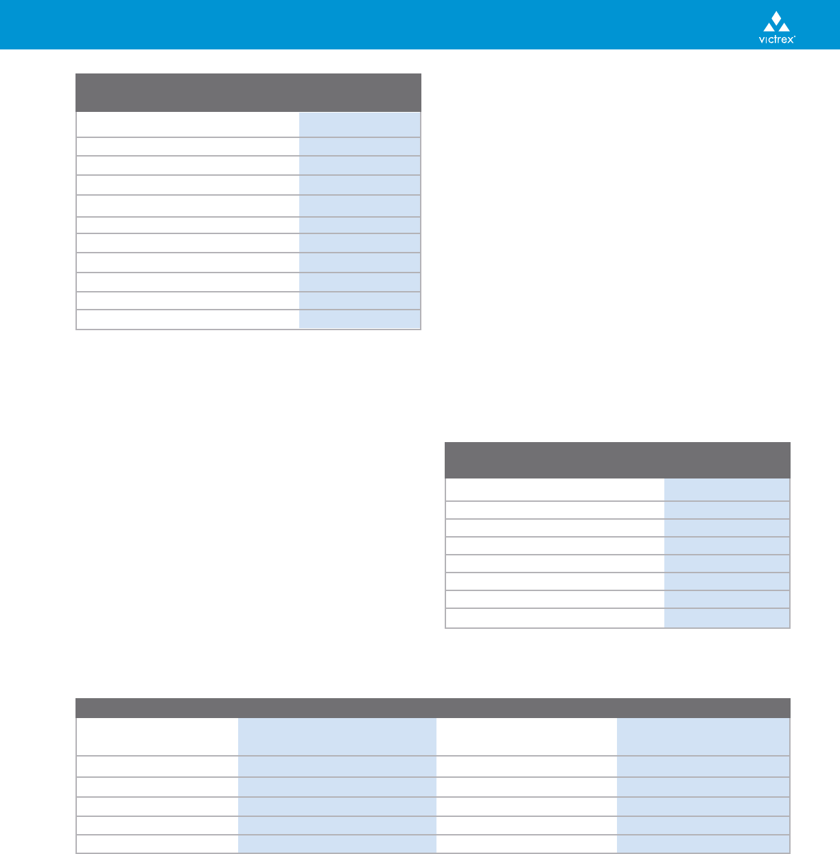
The difference between the “With Flow” and “Across
Flow” shrinkage values in Table 1 represents typical
minimum and maximum values observed in
VICTREX PEEK molding. The fan-gated plaque mold ori-
entates the melt, fibers and crystalline regions, so that a
less orientated molding should exhibit mold shrinkage
values between these two extremes. The annealed shrink-
age values in Table 1 are obtained by post process thermal
treatment in order to reach the maximum degree of crys-
tallinity. These shrinkage values may be expected in com-
ponents which are subsequently used in high temperature
environments.
Most injection molding machines have the facility for a
multi-stage injection. In order to reduce mold shrinkage
and to enhance filling, a second stage packing pressure
should be applied once the mold is full. The potential for
severe mold shrinkage may be prevented at the tool
design stage by minimizing section thickness. Molded
component tolerance may be defined as the dimensional
variation observed in seemingly identical moldings. The
tolerances shown in Table 2 were determined using the
fan-gated test plaques previously described.
% Tolerance (Molded) % Tolerance (Annealed)
Grade With Flow Across Flow With Flow Across Flow
VICTREX
450G 0.05 0.07 0.05 0.07
VICTREX
450GL30 0.07 0.08 0.03 0.05
VICTREX
450FC30 0.04 0.04 0.04 0.06
VICTREX
450CA30 0.05 0.09 0.05 0.11
* This data represents variation from the mean found in 20 samples
Table 2: Typical Tolerance Values for VICTREX PEEK*
OPERATING CONDITIONS
The optimum operating conditions for each individual
injection molding machine will depend on many vari-
ables. This section presents an overview of the practical
aspects of injection molding VICTREX PEEK based on gen-
eral experience. Table 3 shows the recommended temper-
atures required to successfully mold VICTREX PEEK.
Table 1: Typical Mold Shrinkage Values for VICTREX PEEK
170°C (338°F)
210°C (410°F)
Annealed
170°C (338°F)
210°C (410°F)
Annealed
170°C (338°F)
210°C (410°F)
Annealed
170°C (338°F)
210°C (410°F)
Annealed
170°C (338°F)
210°C (410°F)
Annealed
170°C (338°F)
210°C (410°F)
Annealed
170°C (338°F)
210°C (410°F)
Annealed
170°C (338°F)
210°C (410°F)
Annealed
170°C (338°F)
210°C (410°F)
Annealed
170°C (338°F)
210°C (410°F)
Annealed
170°C (338°F)
210°C (410°F)
Annealed
170°C (338°F)
210°C (410°F)
Annealed
170°C (338°F)
210°C (410°F)
Annealed
170°C (338°F)
210°C (410°F)
Annealed
170°C (338°F)
210°C (410°F)
Annealed
170°C (338°F)
210°C (410°F)
Annealed
3 mm
(0.118 in)
6 mm
(0.236 in)
3 mm
(0.118 in)
6 mm
(0.236 in)
3mm
(0.118 in)
6 mm
(0.236 in)
3 mm
(0.118 in)
6 mm
(0.236 in)
3 mm
(0.118 in)
6 mm
(0.236 in)
3 mm
(0.118 in)
6 mm
(0.236 in)
3 mm
(0.118 in)
6 mm
(0.236 in)
3 mm
(0.118 in)
6 mm
(0.236 in)
450G
381G
150/151G
450GL30
150GL30
450CA30
150CA30
450FC30
1.2
1.4
1.6
1.7
2.3
2.3
1.2
1.4
1.4
1.6
2.2
2.3
1.3
1.6
1.8
1.9
2.1
2.3
0.4
0.4
0.4
0.5
0.5
0.5
0.3
0.3
0.4
0.4
0.4
0.4
0.0
0.1
0.1
0.2
0.2
0.3
0.0
0.0
0.0
0.1
0.1
0.1
0.3
0.3
0.4
0.4
0.4
0.4
1.5
1.7
1.9
1.8
2.2
2.4
1.5
1.6
1.8
1.7
2.2
2.3
1.5
1.8
2.0
1.9
2.1
2.3
0.8
0.9
1.0
0.8
0.9
1.0
0.9
1.0
1.2
0.9
1.1
1.1
0.5
0.5
0.7
0.6
0.7
0.7
0.6
0.6
0.7
0.6
0.6
0.7
0.5
0.6
0.8
0.7
0.7
0.7
Mold Flow Across
Grade Thickness Temperature % Flow %

Fault Possible Cause Remedy
Dark Color and/or Low Mold Temperature Increase Mold Temperature
Transparent Edges
Short Moldings Insufficient Material Injected Increase Shot Size
Inadequate Flow of Melt Increase Injection Pressure
Increase Barrel Temperatures
Increase Mold Temperatures
Increase Injection Speed
Incorrect Design Increase Gates, Sprues or Runner Size
Improve Gates, Sprues or Runner Design
Change Position of Gate
Increase Venting
Brittle Moldings Overheating in the Barrel Reduce Barrel Temperatures
Reduce Cycle Time
Decrease Screw Speed
Molded-In Stresses Increase Barrel Temperatures
Reduce Injection Pressure
Increase Cycle Time
Increase Mold Temperatures
Increase Gates, Sprues or Runner Size
Weld Lines Increase Barrel Temperatures
Increase Injection Speed
Increase Mold Temperatures
Change Gate Design or Position
Cold Slug Material Freezing Increase Nozzle Temperature
of Polymer in the Nozzle Thermally Insulate Nozzle
Employ Decompression
Use a Sprue Break
9
Troubleshooting
Rear Temp. Middle Temp. Front Temp. Nozzle Temp.
Grade °C (°F) °C (°F) °C (°F) °C (°F)
VICTREX
150G/151G 350(662) 355(671) 360(680) 365(689)
VICTREX 381G 350(662) 360(680) 365(689) 370(698)
VICTREX 450G 355(671) 365(689) 370(698) 375(707)
VICTREX
450G Black 903 355(671) 365(689) 370(698) 375(707)
VICTREX
150GL30 355(671) 360(680) 370(698) 375(707)
VICTREX
450GL30 360(680) 365(689) 370(698) 375(707)
VICTREX
150CA30 360(680) 370(698) 380(716) 385(725)
VICTREX
450CA30 365(689) 380(716) 390(734) 395(743)
VICTREX
150FC30 355(671) 360(680) 370(698) 375(707)
VICTREX
450FC30 360(680) 365(689) 375(707) 380(716)
Table 3: Recommended Starting Temperatures
for an Injection Molding Machine Prepared for
VICTREX PEEK
INJECTION PRESSURES AND SCREW SPEED
Hydraulic injection pressures of 70 to 140 MPa (10,150
to 20,300 psi) are initially used with hydraulic holding
pressures of 40 to 100 MPa (5,800 to 14,500 psi). A nom-
inal hydraulic back pressure of up to 30 bar (435 psi) is
necessary to create an homogeneous melt and aid con-
sistency of shot size.
A screw speed of between 50 and 100 rpm is optimum
for the transport and melting of VICTREX PEEK.
However, low screw speeds (50-60 rpm) are recom-
mended for the reinforced grades to prevent excessive
fiber breakdown. Screw speeds lower than 50 rpm
should be avoided since this results in longer cycle
times. Screw speeds higher than 100 rpm are not rec-
ommended because they can cause excessive localized
shear heating.
continued

10
Fault Possible Cause Remedy
Voids and Insufficient Time or Increase Injection Pressure
Surface Sinking Pressure in Mold Increase Holding Time
Reduce Barrel Temperatures
Incorrect Mold Design Increase Gates, Sprues or Runner Size
Increase Holding Pressure
Streaking Overheated Material Reduce Barrel Temperatures
Reduce Nozzle Temperature
Reduce Residence Time
Reduce Injection Speed
Reduce Screw Speed
Damp Material Dry Material
Dead Spots in Barrel Streamline Barrel and Nozzle
Clean Screw, Barrel and Nozzle
Check for Damages, Pitting, etc.
Burn Marks Air Trapped in Cavity Reduce Injection Pressure
Reduce Injection Speed
Improve Venting of Cavity
Change Gate Position, Size or Type
Flashing or Inadequate Locking Force Reduce Injection Pressure
Mold Opening Reduce Injection Speed
Reduce Cylinder Temperature
Reduce Mold Temperature
Reduce Speed Setting
Increase Locking Force
Incorrect Mating or Re-Grind and Re-Align the Mating Surfaces
Bending of the Mold Install Heavy Backing Plates
Check for Foreign Matter Between the Plates
Warping or Temperature Difference Adjust Temperature so It Is the Same
Distortion in the Mold on Both Halves of the Mold
Lack of Section Symmetry Consider Re-Design of Cavity, Runners
and Gates
Use a Temperature Differential Between the
Two Halves of the Mold to Compensate
Use a Cooling Jig
Increase Cooling Time
Early Ejection Increase Cooling Time
Reduce Mold Temperatures
Add More Ejector Pins
Orientation of Fibers Change Gate Position
in Material Reduce Injection Speeds
Insufficient Rigidity Change Design of Components
(e.g., Add Ribs, etc.)
Increase Section Thickness
Jetting Material Entering the Cavity Reduce Injection Speed
too Quickly Change Position and/or Type of Gate
Melt too Cold Increase Melt Temperature
Excessive Processing Conditions Reduce Tool Temperature
Shrinkage Increase Injection Pressure
Increase Holding Pressure
Gate too Small Increase Gate Size
Surface Frosting Insufficient Injection Speed Increase Injection Speed
(Reinforced Grades) Increase Mold Temperatures
Increase Barrel Temperatures
Over-Shearing the Melt Decrease Screw Speed
Troubleshooting

11
EXTRUSION
Many polymer processing techniques are essentially an
extrusion operation employing specific downstream
equipment. These techniques include wire coating, pro-
file extrusion, film, sheet and monofilament production.
MACHINE DESIGN
VICTREX PEEK and compounds are readily extruded
using conventional processing technology. There are
specific requirements which are detailed below.
BARREL TEMPERATURES
Cylinder heaters must be capable of reaching 400°C
(752°F) and maintaining set temperatures to within
± 2°C (4°F). Therefore, cast aluminum heaters are not
suitable and should be replaced with either high tem-
perature alloy or ceramic heaters. Cylinder heaters
should cover all exposed metal surfaces to ensure an
even temperature distribution. Areas which cannot be
heated directly should be covered with high tempera-
ture thermal insulation to prevent the formation of
“cold spots.”
BARREL CAPACITY AND RESIDENCE TIME
The size and the output of the extruder should be
matched to obtain a short residence time, typically 5 to
10 minutes. There should be no “dead spots” i.e., gaps
around flanges or badly fitting blanking plugs. All
internal surfaces should be cleaned and polished
before extrusion commences.
SCREW DESIGN
The materials in the VICTREX PEEK grade range are
compatible with most conventional screw designs. The
only screw specifically not recommended is a continu-
ous compression “PVC” type. This screw has virtually
no feed section which results in the compacting of
polymer, leading to excessive torque. For a more
detailed overview of screw design, see Screw Design,
page 6.
WIRE AND CABLE COATING
VICTREX PEEK is widely used in the wire and cable
industry. Applications include primary insulation,
sheathing and as top coat material for wires and cables.
DIE AND CROSSHEAD DESIGN
VICTREX PEEK insulation is generally applied using a
pressure die or a “tube-on” system. Pressure dies allow
a specific thickness of coating to be metered directly
onto the conductor as it is pulled through the die.
Tube-on dies extrude the polymer outside the
crosshead and the conductor is drawn through the die
and melt. The melt is drawn and adheres to the con-
ductor, forming an insulating layer of the desired thick-
ness. The “draw-down” is expressed as a ratio of the
cross sectional area of the annulus to that of the final
coating. The recommended draw-down ratio for natur-
al VICTREX PEEK is between 3:1 and 10:1. Tube-on die
systems are more frequently used as they allow thinner
coatings of VICTREX PEEK to be applied.
The crosshead design for tube-on systems is not critical
to the process. However, the preferred design is a sin-
gle flow splitter which redirects the melt through 90°
while maintaining good stream-lined flow. Although
more complex flow splitters have proved satisfactory in
service, these systems are more difficult to clean.
WIRE AND CABLE CRYSTALLINITY
Many of the outstanding physical properties of natural
VICTREX PEEK result from its semi-crystalline morphology.
In wire and cable coating, the melt is drawn from the
die crosshead and allowed to cool in the air for approx-
imately 1 meter. While cooling, the color of natural
VICTREX PEEK changes from transparent dark brown to
an opaque grey. This change in color is due to cooling
and crystallization of the surface of the insulation.
Once this transition has taken place, additional water
cooling may be used since crystallization within the bulk
of the molten polymer will not be affected.
The temperature of the conductor may retard crystal-
lization in wire and cable coating operations.
Therefore, whenever possible, it is advisable to heat the
conductor prior to entry into the crosshead. The pre-
heat temperature will depend on the nature and
geometry of the conductor, but excellent results have
been achieved with temperatures in the 120°C to 200°C
(248°F to 392°F) range. If the desired level of crystallinity
cannot be achieved on-line, it is possible to post-crystallize
the insulation by subsequent thermal treatment.
EXTRUDER SIZE AND CONTROL
The residence time of the polymer in the process equip-
ment influences the quality of the final insulation. The
thermal stability of VICTREX PEEK is exceptional, but
gel formation can occur during processing and manifest
itself as a gritty surface on the insulation. The screen
packs disperse these gels very effectively in the melt,
but any gels created downstream will be present in the
extrudate. Therefore, the capacity and throughput of
the extruder should be matched.

12
SHEET MANUFACTURE
Natural VICTREX PEEK may be used to form sheets. The
processing is carried out using a conventional extruder
with suitable die and haul-off equipment, as depicted in
Figure 7.
A general guide to the processing conditions required
to successfully form sheets from VICTREX PEEK is given
in Table 4.
DIE DESIGN
Slot dies are recommended for processing natural
VICTREX PEEK into sheets. These systems should have a
streamlined melt flow with polished interiors to pre-
vent hold-up or die stick-slip. The temperature of the
die lip is crucial for good surface finish and dimensional
control. Die lips should be maintained at 380°C (716°F)
± 2°C (4°F).
THIN FILM AND SHEET CRYSTALLINITY
Thin sheet [500 µ (< 0.02 in)] may be produced in either
semi-crystalline or amorphous form by controlling the
temperature of the casting drums. A drum temperature
of 50°C (122°F) will produce an amorphous transparent
film, while a 170°C (338°F) temperature will give
opaque semi-crystalline film. As the thickness of the film
increases [500 µ (< 0.02 in)], it becomes more difficult to
control the degree of crystallinity. If necessary, the level
of crystallinity within films can be optimized through
post process thermal treatment.
MONOFILAMENT
VICTREX PEEK may be processed to form monofilament
using an extruder with downstream haul-off and draw
facilities. Extruders used for the production of monofil-
ament are generally fitted with gear pumps. These
ensure that an accurately metered supply of melt is fed
to the die at constant pressure. Other non-metered sys-
tems have proved satisfactory in service. A typical
monofilament production line is depicted in Figure 8.
The post-extruder processing depicted in Figure 8 can
be considered in two distinct parts: melt orientation
and relaxation. During melt orientation the extrudate is
air and water cooled at a haul-off velocity of V
1
. The
filament is drawn at a velocity V
2
through an oven
which is set above the glass transition of the material.
The difference in velocities V
1
and V
2
serves to draw
the polymer, reducing the diameter and orienting the
filament.
During melt relaxation, the polymer is “heat set” by
passing through a second oven (velocity V
3
) which is
close to the melt temperature of the material. The dif-
ference in velocities V
2
and V
3
serves to relax the poly-
mer, increasing the diameter of the monofilament.
Typical values of temperature and velocity for the pro-
duction of a 0.4 mm (0.016 in) diameter monofilament
from a 40 mm (1.57 in) diameter single screw extruder
are given in Table 5.
S
Water Quench
Temperature
T
1
V
1
Drawing Oven Heat Setting Oven
Figure 8: A Schematic Representation of Monofilament
Production Equipment
T
2
V
2
V
3
T
3
Figure 7: Sheet Producing Equipment
Screw 32 mm (1.26 in) Diameter Screw
Die 300 mm (11.81 in) Slot die
Screw Speed 40 rpm
Filters 2 layers of 400# woven stainless steel
mesh plus supporting mesh fitted into
the breaker plate
Rear Middle Front
Cylinder
Temperatures 340°C (644°F) 375°C (707°F) 375°C (707°F)
Die Lips 380°C (716°F)
Die Temperatures 380°C (716°F)
Table 4: Typical Conditions for Extruding Sheets
Using VICTREX PEEK
Slot
Die
Three
Roll
Stack
Extruder
Melt Temperature 375°C (707°F)
Filter Pack 3 x 200#
Die to Water Surface Distance (S) 700 mm (27.5 in)
Water Quench Temperature T
1
60°C (140°F)
Draw Down Ratio V
2
:V
1
3.5 : 1
Drawing Oven Temperature T
2
200°C (392°F)
Heat Setting Oven Temperature T
3
280°C (536°F)
Draw Relaxation V
3
:V
2
0.95 : 1
Output 3.1 kg h
-1
(6.8 lb h
-1
)
Die (16 Hole) 1.12 mm (0.044 in)
Monofilament Diameter 0.4 mm (0.016 in)
Table 5: Typical Monofilament Production Conditions
for a Single Screw Extruder
Energy to Break 1.24 J (0.91 ft lbs)
Tensile Load at 2% Elongation 1.18 kg (2.6 lbs)
Tensile Load at 5% Elongation 1.77 kg (3.9 lbs)
Tensile Load at 10% Elongation 2.66 kg (5.86 lbs)
Tensile Load at Break 5.81 kg (12.8 lbs)
Elongation to Break 22.0%
Knot Strength 2.42 kg (5.34 lbs)
Shrinkage in Air at 200°C (392°F) 3.5%
Table 6: Properties of a 0.5 mm (0.02 in) Monofilament
Prepared as Specified in Table 5
Test Tensile Stress (yield) Tensile Stress (break) Modulus
Temperature MPa (psi) MPa (psi) GPa (psi)
23°C (73°F) 110 (16,000) 325 (47,100) 6.9 (1,000,000)
100°C (212°F) 70 (10,200) 280 (40,600) 5.7 (827,000)
150°C (302°F) 45 (6,500) 250 (36,300) 5.3 (769,000)
250°C (482°F) 20 (2,900) 120 (17,400) 0.9 (131,000)
300°C (572°F) 6 (870) 90 (13,100) 0.25 (36,300)
Table 7: Retention of Monofilament Properties at Elevated Temperatures
13
MONOFILAMENT ORIENTATION
The physical properties of natural VICTREX PEEK can be
modified by solid state orientation. If the filament is to
be oriented in a second stage process, it must be
quenched upon leaving the die so that it becomes
amorphous. However, care must be taken not to cool
the filament too rapidly or voids will form. Air cooling
followed by immersion in a water bath or direct immer-
sion into a heated water bath have both proven suc-
cessful in service. The optimum distance from the die to
the water bath and the temperature of the water
depend on the thickness of the filament. However, a
small diameter [0.25 mm (0.01 in)] filament would typi-
cally require a 100 to 200 mm (4 to 8 in) air cooling fol-
lowed by a water quench at 20°C to 50°C (68°F to
122°F). If the monofilament temperature is too high,
then the water in the bath will boil locally causing mar-
ring on the polymer surface.
VICTREX PEEK will be oriented using either a single stage
(Figure 8) or a two stage draw where the filament is
necked at 120°C (248°F) and then drawn at 200°C (392°F).
The properties which develop in the drawn filament will
be dependent on the level of draw-down. Draw-down
ratios between 2.5:1 and 3:1 are recommended. Above
3:1, the knot strength of the filament decreases rapidly.
The maximum sustainable draw-down that has been
achieved using VICTREX PEEK is 3.8:1.
When orientation is developed in the monofilament, it
is necessary to heat set it under tension. Heat setting is
usually carried out at a temperature approaching the
melting point of the polymer (typically 6 seconds at
280°C (536°F) under a draw relaxation of 0.95:1). The
resultant monofilament is tough, highly oriented, and
has a controlled diameter which will retain its set form
above the glass transition temperature of the material.
Typical physical properties of such monofilaments are
shown in Tables 6 and 7.

14
COMPRESSION MOLDING
The following information is only a guide to produce
compression molded parts based on historical informa-
tion and data generated over several years. Processors
may well have to modify their conditions i.e. pressures
and temperatures according to the parts being produced.
BASIC PROCESS
The polymer, which will be generally VICTREX 450PF
(bulk density <0.6 g cm
-3
) grade fine powder needs to
be pre-dried for 3 hours at 150°C (302°F) or overnight
at 120°C (248°F), to try and avoid the problems of
porosity/bubbles. Normal VICTREX PEEK powder or
pellets can be compression molded but granular bound-
ary marks will always be evident and will be a weak
point in the molding. Drying the polymer in the mold
itself is acceptable but drying times may need to be
adjusted depending on the depth of material. The
mold tools themselves should be pre-dried at around
150°C (302°F) before use. A small amount (2-3%) of
PTFE lubricant grade powder compounded into the
VICTREX PEEK may aid part ejection.
The dried polymer with ~ 102% of the theoretical
weight of polymer required to form the component is
compacted in the mold with a pressure of between 350
to 700 bar (5000 and 10,000 psi) to enable the trapped
air in the mold to escape before the mold is heated up.
The heating of the mold can be accomplished by
preferably internal and external heater bands or if
heater bands are not available an air-circulating oven
can be used. Prior to heating the mold, the pressure
should be “backed off” to 140 bar (2000 psi).
The temperature of the mold is raised to 390 - 400°C
(734 - 752°F) as fast as the heaters will allow until the
polymer is fully molten. The pressure should be held for
15 minutes for every 25 mm (1 in) section thickness.
Some flashing may occur but this is normal.
The molding is then cooled down at a rate of approxi-
mately 40°C (72°F) per hour while still under pressure
until the part has reached <150°C (302°F) when the
part can be ejected. The use of thermocouples should
be used to monitor cooling rate.
EQUIPMENT REQUIREMENTS
Press: Should be capable of delivering sufficient pres-
sure. Typically up to 700 bar (10,000 psi).
Molds: Should be corrosion resistant metals. Good
results have been obtained with Stavax, Duplex
(Ni/Chromium) and hard chrome plated stainless steel,
also P20 hard tool steel with a Rockwell hardness of 50
has been used with success. Mild steel and steels con-
taining copper should not be used. Mold surfaces in the
line of draw should be polished to aid ejection.
A mold release agent is recommended such as one of
the Frekote products (without silicon) to aid ejection.
Clearance between sliding parts should be between
0.075 and 0.125 mm (0.003 and 0.005 in). PTFE, alu-
minum, steel (20-30 Rockwell) sealing rings have been
used with effect between the punch plate and the
molten polymer.
Internal and external heater bands are preferable but a
hot air circulating oven capable of achieving at least
400°C (752°F) can be used. Care should be taken to
avoid thermal degradation of the polymer.
COMPRESSION MOLDING CHARACTERISTICS
Properties of compression molded VICTREX PEEK parts
differ from injection molded parts. As a general rule
the compression molded parts are more crystalline,
have a higher modulus and tensile strength, are harder
but have a lower ductility and can be more brittle.
Milled fibers (glass and carbon) may be compounded into
VICTREX PEEK for compression molding albeit with loss of
anisotropy, lower strength, different C.T.E. and different
tribological properties than injection molded parts.
Very thick sections may be subject to cracking and a post
processing thermal treatment (annealing) should be used
to relieve stresses. See Victrex literature on annealing.
Close tolerances cannot be achieved directly therefore
components must be machined. See Victrex literature
on machining. The outer and inner surfaces of mold-
ings may be discolored due to the mold release agent
and being in contact with the tooling, these surfaces
should be skimmed to remove the discoloration.
POWDER COATING
VICTREX PEEK in fine powder form may be used to coat
metal substrates. Thick coats of up to 2 mm (0.078 in)
can be applied by electrostatic spraying or fluidized
bed coating. Coatings as thin as 25 µ (0.001 in) may be
obtained using dispersion techniques.
Regardless of whether a part is coated by the electro-
static or dispersion process, the appearance of the coat-
ing can be modified via the last heat cycle. Three sur-
face finishes are possible; standard crystalline (air
cooled), amorphous (quenched in cold water*) or gloss
(quenched in cold water and subsequently annealed to
achieve a gloss finish).
* Parts that are quenched can generate steam and localized boiling water.

15
ELECTROSTATIC SPRAY AND FLUIDIZED BED
COATING
Electrostatic spray and fluidized bed coating are both
methods of transporting solid VICTREX PEEK powder
onto the heated surface of the metal substrate. Once
the fine powder comes into contact with the metal, the
particles adhere to the surface and eventually form a
cohesive layer.
Electrostatic spray techniques generally involve the air
transportation of fine powder to the nozzle of an elec-
trostatic spray gun. A large potential difference is
applied between the nozzle and the substrate, which
serves to direct the jet of fine powder. Fluidized bed
techniques use pressurized gases to circulate a given
mass of fine powder material in a fixed volume. A con-
trolled cloud of powder is created into which the heat-
ed substrate may be lowered.
Before coating, substrates should be prepared by grit
blasting and degreasing in appropriate solvents. This
will remove contamination and properly prepare the
surface of the metal for polymer adhesion. The metal
substrate should be heated to between 400°C and
420°C (752°F and 788°F) and the fine powder coating
applied. Oxidation will reduce the surface energy of
the metal and lead to poor adhesion. Therefore, freshly
prepared surfaces are recommended for the best
results and exposure of the heated metal to oxygen
should be minimized or avoided, if possible.
After the final coating the part should be placed into
the oven for final “flow-out” of the VICTREX PEEK
coating and then removed from the oven and allowed
to cool. The degree of crystallinity within the coating
may be controlled by the cooling regime imposed.
Amorphous layers are frequently post conditioned to
reach the optimum level of crystallinity by placing the
component in an air circulating oven at 200°C (392°F)
for 30 minutes.
When coating components with a large thermal mass,
slower cooling rates will cause the development of
high levels of crystallinity which may cause cracking of
the coating. Levels of crystallinity can be controlled by
ensuring that the coating is cooled at an appropriate
rate, for example, by the use of a cool air flow. Water
quenching may lead to thermal shock and is not recom-
mended.
DISPERSION SPRAY COATING
VICTREX PEEK-based coatings in a range of 25 to 100 µ
(0.001 to 0.004 in) thickness can be applied using dis-
persions of VICTREX PEEK fine powder in an aqueous
medium. Dispersions can be used to coat stainless and
carbon steels, aluminum, castings and ceramics. Since
they are based on high-flow VICTREX PEEK, dispersions
are ideal for coating complex geometries and provide
superior coverage around holes, deep draws and recesses.
Like other types of VICTREX PEEK-based coatings, dis-
persion coatings have very low wear and friction prop-
erties, superior chemical and steam resistance, excellent
mechanical properties (hardness, creep resistance, etc.)
as well as low extractable content and good purity.
FINISHING OPERATIONS
Components made from VICTREX PEEK and compounds
may be used in a number of finishing operations such
as machining, bonding, coloring or metallization.
MACHINING
Often, for prototype designs or short production runs,
it is not economically viable to manufacture an injec-
tion molding tool. Under such circumstances, it is com-
mon to machine VICTREX PEEK materials to form com-
ponents. VICTREX PEEK may be machined and finished
using the same techniques and equipment as for other
engineering thermoplastics. However, due to the excel-
lent physical properties and wear characteristics of
these materials, it is necessary to use carbide or dia-
mond tipped tools and bits.
Machining and finishing operations on polymeric materi-
als can release molded-in or residual stresses. Before
machining, components formed from VICTREX PEEK
should be annealed to relieve stress. An annealing proto-
col is detailed in the section on Annealing. During
machining or finishing, further stresses may be built-up
within the material by localized heating at the cutting
point. Therefore, if a large amount of machining and
finishing is to be carried out on a component, a second
annealing procedure prior to finishing is recommended.
The thermal conductivity of all polymeric materials is
lower than that of metals, so heat build-up during
machining is rapid. A cooling fluid should be used to
remove some of the heat generated by working the mate-
rial. Water is generally recommended for use with all the
VICTREX PEEK based materials. A summary of the suggest-
ed machining guidelines is shown in Table 8 (page 16) .
PROTOTYPE PERFORMANCE
Prototype components are generally the best way to
evaluate the performance of a material under a certain
set of application-specific conditions. However, the
physical performance of a machined component will
differ slightly from that of a seemingly identical injec-
tion-molded component. This phenomenon may be
explained in terms of the inherent physical conse-
quences of a molding procedure, including the produc-
tion of skin/core effects and fibre orientation.

16
ANNEALING
Components formed from VICTREX PEEK can be
annealed to increase levels of crystallinity, remove any
thermal history, limit subsequent dimensional changes
at high temperatures, or to remove stresses. The appro-
priate annealing procedure will depend on the objec-
tive of the process.
AN OVERVIEW OF ANNEALING FOR
OPTIMUM CRYSTALLINITY
Increasing crystallinity within a component may be nec-
essary if a brown amorphous skin is observed (this can
also be eliminated by increasing mold temperature), or
enhanced strength and chemical resistance is required.
(a) Dry the component for a minimum of three hours at
150°C (302°F).
(b) Allow the component to heat up at 10°C (18°F) per
hour until an equilibrium temperature of 200°C
(392°F) is reached.
(c) The holding time for components is dependent on
section thickness. It is recommended that annealing
temperatures are held for at least 4 hours.
(d) Allow the component to cool at 10°C (18°F) per
hour until the system falls below 140°C (284°F).
(e) Switch off the oven and allow the component to
cool down to room temperature.
Annealing temperatures close to 300°C (572°F) have
been used to maximize mechanical performance
(strength and modulus) and chemical resistance.
However, these effects may be accompanied by embrit-
tlement and surface oxidation because of the high
annealing temperature.
AN OVERVIEW OF ANNEALING TO REMOVE
STRESSES
Injection molding or machining operations may add
stresses to a component. These stresses reduce the
physical performance of devices and may be removed
by annealing the sample as described above, with a
holding temperature up to 250°C (482°F).
AN OVERVIEW OF ANNEALING TO REMOVE
THERMAL HISTORY AND SHRINKAGE
Dimensional stability over a wide temperature range
may be crucial to some applications. Components may
be annealed to remove distortion effects or thermal
history.
(a) Dry the component for a minimum of three hours
at 150°C (302°F).
(b) Allow the component to heat up at 10°C (18°F) per
hour until an equilibrium temperature which
exceeds the normal service temperature is reached.
(c) The holding time for components is dependent on
section thickness. It is generally recommended that
temperatures are maintained for at least 4 hours.
(d) Allow the component to cool at 10°C (18°F) per
hour until the system falls below 140°C (284°F).
(e) Switch off the oven and allow the component to
cool down to room temperature.
Units VICTREX PEEK Reinforced VICTREX PEEK Compounds
TURNING
Cutting Speed m min
-1
(ft min
-1
) 300 (984) 120-180 (394-590)
Feed mm rev
-1
(in rev
-1
)0.4 (0.016) 0.2 (0.008)
Relief Angle ° 5 5
Top Rake Angle ° 6-12 6 - 12
Cutting Depth mm (in) 6.5 (0.25) 7.5 (0.29)
Coolant None None
MILLING
Cutters - Standard or Carbide Tip Carbide Tip or Diamond Tip
Cutter Speed m min
-1
(ft min
-1
) 590-754 (180-230) 78-110 (256-361)
Coolant - Water/Oils Water/Oils
DRILLING
Cutting Speed m min
-1
(ft min
-1
) 120 (394) 75-120 (246-394)
Feed mm rev
-1
(in rev
-1
) 0.05-0.20 (0.002-0.008) 0.05-0.20 (0.002-0.008)
Lip Angle ° 118 118
Clearance Angle ° 12 12
Coolant - Water/Oils Water/Oils
REAMING
Runners - Spiral Flute Spiral Flute
Speed rev min
-1
100-200 100-200
Coolant - Water/Oils Water/Oils
Table 8: Guidelines for the Machining and Finishing of VICTREX PEEK

17
IF - adhesive failure at the adhesive / substrate interface
CF - cohesive failure of the adhesive, leaving adhesive on both sides of the substrate
SF - the adhesive is of sufficient strength to cause failure within the VICTREX PEEK substrate
ICF - mixed mode failure with fracture propagation switching between interfacial and cohesive failure
ADHESIVE BONDING
VICTREX PEEK and compounds may be bonded using a
variety of common adhesives. For specific adhesive
applications please contact Victrex for recommendation.
ADHESIVE TYPES
Most adhesive types are compatible with the VICTREX
PEEK-based materials. Epoxy, cyanoacrylate, anaerobic
and silicone adhesives have been shown to successfully
bond VICTREX PEEK. A list of typical adhesives and
their corresponding bond strengths is shown in Table 9.
From the data shown in Table 9 it is clear that some of
the epoxy systems tested give superior bond strengths
to other conventional adhesives.
SURFACE PREPARATION
Surfaces which are to be joined by an adhesive bond
should be clean, dry and free from grease and other
contamination.
There are a variety of surface treatments available
which increase the strength of adhesive bonds made
with VICTREX PEEK. A comparison of bond strengths
achieved using the most common of these techniques is
made in Table 10. For these measurements VICTREX
450G samples were bonded together in a single over-
lap shear geometry with a two-component epoxy from
Ciba (AV138M/HV998) and using a 15 minute 100°C
(212°F) curing cycle.
WELDING
VICTREX PEEK may be bonded using conventional ther-
moplastic welding techniques. However, these materi-
als have exceptionally high melt temperatures, and
considerable amounts of energy must be put into the
interface to achieve a good bond. Satisfactory results
have been obtained using hot plate, friction and near-
field ultrasonic welding.
Bond Strength/MPa (psi)
Untreated 0.7 (102)
Roughening 2.1 (305)
Acid Etch 5.5 (798)
Excimer Laser 5.6 (812)
UV Lamp 5.0 (730)
Plasma Chamber 5.0 (722)
Table 10: Comparison of Surface Preparation Techniques
for Adhesive Bonds to VICTREX 450G
VACUUM METALLIZATION
VICTREX PEEK materials may be used as substrates in a
thermoplastic metallization process. Care should be
taken when injection molding or machining such com-
ponents to ensure a good surface finish. A poor finish
will result in a non-uniform coating. Substrates must be
clean, dry and free of contamination before the appli-
cation of the metal coating.
COLORING VICTREX PEEK
VICTREX PEEK is available in a natural grey color or as a
black material. The color is modified by its constituents,
i.e., carbon reinforced materials are black in color while
glass fiber reinforced materials are a light grey.
VICTREX PEEK may be colored using a masterbatch
additive.
Failure Stress / MPa (psi)
Adhesive Type Manufacturer 23°C 120°C 150°C 200°C
S-4215 RA Acrylic tape ATP Adhesive Systems 0.2 (29) CF 0.03 (4.3) CF - -
Araldite AV138M + HV 998 Epoxy Huntsman 5.5 (800) IF + CF 3.4 (500) CF - -
Araldite AV 119 Epoxy Huntsman 41.8 (6000) SF 4 (575) CF 1.5 (225) IF + CF -
HAF 8401 Nitrile rubber Tesa AG 47.3 (6850) SF 2.4 350) IF 1.9 (275) IF -
phenolic resin
Duralco 4460 Epoxy Cotronics Corp. 1.7 (250) ICF - 0.5 (75) CF 0.4 (58) IF +CF
Duralco 4703 Epoxy Cotronics Corp. 16.7 (2400) SF - 3.4 (500) CF 1 (145) CF
EPO-TEK 353 ND Epoxy Epoxy Technology 36.2 (5250) SF - 3.1 (450) CF 1 (145) IF + CF
Duralco 4525 Epoxy Cotronics Corp. 3.3 (475) CF - - 0.6 (87) CF
Table 9: Bond Strength of Various Adhesives with VICTREX PEEK-Based Materials

18
POLYMER SPECIFICATIONS AND APPROVALS
VICTREX PEEK and compounds are recognized or approved by the following bodies:
AEROSPACE/MILITARY
FAR 25-853 VICTREX 381G, 450G, 450GL30 and 450CA30 meet the fire, smoke and toxicity standard
FAR 25-853 for aircraft cockpit use.
ATS 1000.001 VICTREX 381G and 450G meet the fire, smoke and toxicity standard ATS 100.001 for optical
density and toxicity of fumes from burning.
SP-R-0022A VICTREX 450G meets the NASA standard SP-R-0022A for vacuum stability of polymeric
materials in spacecraft applications.
BMS 8-317A VICTREX PEEK unfilled glass and carbon filled polymers can be supplied to Boeing specification
BMS 8-317A for use in aircraft applications.
MIL-P-46183 VICTREX PEEK and compounds can be supplied to the military specification MIL-P-46183.
Staining Test VICTREX 381G complies with the Boeing Aircraft staining test.
#DMSRR 1018 VICTREX CA30 complies with the Rolls Royce standard #DMSRR 1018.
75-T-2-3007-4-1 VICTREX CA30 meets the Deutsche Aerospace/Airbus standard 75-T-2-3007-4-1.
MS29.02.03 VICTREX 450GL30 can be supplied to Sundstrand Aerospace materials specification MS29.02.03
JAR 25.853 VICTREX 381G meets the fire, smoke and toxicity standard JAR 25.853 for flame resistance.
S26 4625 VICTREX 381G meets the fire, smoke and toxicity standard S26 4625 for non-flaming smoke
generation.
VPRM85-10A VICTREX 381G meets the fire, smoke and toxicity standard VPRM85-10A for peak and total
heat release when heated.
299-947-362 All grades of VICTREX PEEK can be supplied to Bell Helicopter specification 299-947-362.
P6240 All grades of VICTREX PEEK can be supplied to General Dynamics specification P6240.
HS13534 VICTREX 450FC30 can be supplied to Hamilton Standard (United Technologies) specification
HS13534.
AUTOMOTIVE
WSK-M 4D-838-A VICTREX 150G and 450G can be supplied to the Ford worldwide specification WSK-M 4D-838-A.
WSS-M-4D X1-X1 VICTREX 150FC30 can be supplied to the Ford worldwide specification WS-SM 4D X1-X1.
MS DB406, Rev C VICTREX 150FC30 can be supplied to DaimlerChrysler material specification MS DB406, Rev C.
FLAMMABILITY RATING
UL94 V-0 VICTREX 450G and compounds (E161131) VICTREX 450GL30 and 450CA30 have an UL94 V-0
rating at .057 in (1.45 mm) thickness.

19
FOOD AND BEVERAGE
21CFR 177.2415 All grades of unfilled VICTREX PEEK have been manufactured and tested to be compliant
with the requirements of FDA regulation 21CFR 177.2415 for use in food contact applica-
tions. Victrex plc accepts no responsibility for the compliance of the final material if other
substances have been added during subsequent processing stages. End users and
processors should note that it is the responsibility of the manufacturer of the food contact
article to assure compliance of the extractive limitations of 21CFR 177.2415.
Sanitary Standard 3-A All unfilled grades of VICTREX PEEK comply with Sanitary Standard 20-21 as multiple-use
plastic materials for use as product contact surfaces for dairy equipment.
EEC 93/9/EEC VICTREX 150P, 380P, 450P, 151G, 381G and 450G complies with an EEC directive 93/9/EEC for
plastic in contact with foodstuffs.
WRCA BS 6920 VICTREX 450G, 450GL30, 450CA30, and 450FC30 meet the Water Research Council Approval
BS 6920 Report M100216/(A-D) for non-metallics in contact with water for human con-
sumption.
INDUSTRIAL
WS-340, Rev. A. VICTREX 450G meets Whitey (Swagelok Valve) material specification WS-340, Rev. A.
WIRE AND CABLE
61-12 VICTREX 450G passes the UK defense standard 61-12 (Part 18, issue 2) as a type 2 wire. This
is a standard for limited fire hazard equipment.
RME 620A VICTREX 450G is approved to London Transport Specification RME 620A for cable covering
in railway rolling stock.
ST 808 VICTREX 450G has been approved by French Railways Standard ST 808.
E/TSS/EX5/6053 VICTREX 450G has been approved by the Central Electricity Generating Board Standard
E/TSS/EX5/6053, issue 3.
EDF HN 3280 VICTREX 450G coated wires pass the French Electricity Generating Board to specification
EDF HN 3280.

20
NOTES

www.victrex.com
