
PCB TERMINAL BLOCKS
PROVIDE VALUABLE ELECTRONIC
INTERCONNECTIONS

Sponsored by
PCB Terminal Blocks Provide Valuable Electronic Interconnections
Designing PCBs with terminal blocks requires
an understanding of the types of terminal
blocks available, the best way for them to
be packaged for delivery, and how to solder
them to reduce the potential for failure.
The printed circuit board (PCB) was introduced almost
90 years ago and has since seen immense changes and
improvements, bringing sophistication to the electronics
world. Printed circuit boards come in a multitude of
sizes and shapes to fit the ever-growing application base
for digital technologies. Multilayer printed circuit boards
have been assembled since the 1960s, and for most
electronic equipment, more than one PCB is used.
Early PCBs were populated with electronic components
such as transistors, diodes, resistors, and capacitors,
all having their own leads. PCBs used a through-hole
arrangement where a hole was placed in the center of a
solder pad, which allowed for the component lead to be
inserted. Once the leads were in place, the components
could be soldered to the pad on the opposite side of the
board using a number of dierent methods, including
manual soldering.
As technologies advanced, digital electronic chips were
developed with a band of pins along their outside edge,
which were oen short enough that they didn’t go
through the board. By the late 1960s, chip manufacturers
were designing and manufacturing surface-mounted
components designed to be mounted directly to the PCB,
allowing for increased manufacturing automation (see
Figure 1). Although through-hole and surface-mounted
technologies can both be used to populate a PCB,
most boards incorporate primarily surface-mounted
components. At the moment, the exception to this rule
would be larger components such as transformers and
heat-sink power electronics.
PCBs are made using substrates and laminates. The
substrate is the base material for the board, typically
some type of fiberglass or fabric that has been
reinforced with resin, creating a sti surface to house
the components so they’ll be able to withstand some
measure of shock and vibration without breaking. The
laminate is a copper clad material that is fused to the
substrate using heat and pressure, and then the copper
is etched away to form the conductive circuitry of the
PCB. Once finished, multiple PCBs can be joined to
create a multilayer board.
Interconnecting PCBs with the outside world requires
connector and terminal block manufacturers to provide
a wide array of products. Dierent industries need
dierent types of interconnections depending on the
specific needs of the application, and there are dierent
mounting methods to consider.
PCB Terminal Blocks
Printed circuit board terminal blocks should oer
highly dependable connections without the need for
wire lugs. For example, you might want to use tubular
screw clamps or box clamps for light duty applications
and screw-cage clamps for heavy-duty applications.
Figure 1: By the late 1960s, chip manufacturers were
designing surface-mounted components that attached directly
to the board for increased manufacturing automation.

Sponsored by
PCB Terminal Blocks Provide Valuable Electronic Interconnections
Although it is recommended that you use ferrules—
especially for export applications or when fine stranded
wires must be terminated—users can also simply strip
and insert the wire and then tighten the screw. Be sure
to use board-mounted terminal blocks that meet or
exceed most international standards and are accepted
worldwide.
The two primary types of PCB terminal blocks are screw
clamp and spring clamp designs. Screw terminal blocks
are simple to use; just insert the wire into the open
clamp, tighten the screw, and remove your screwdriver
for a reliable and safe connection. The benefit of
using a screw-type terminal block is that it can be
eectively manufactured for a wide variety of sizes
and configurations while oering the maximum in wire
eiciency and reliability to the user.
Be sure that the terminal block you select is able to
handle the physical stress of multiple wires mounted in
the same general location without putting undue stress
on the PCB. Terminal blocks must be sturdy and tough
and made from high-impact materials such as polyamide
PA66 and self-extinguishing plastics regardless of where
they are mounted. Note that most terminal blocks
are color-coded so that the user can easily determine
ground wires from hot wires and control wires.
Spring clamp terminal blocks take less time to wire
during installation. Through the use of a narrow
screwdriver or by hand while using a lever, users need
only to open a pre-loaded stainless steel spring. The
wire is then inserted into an opening in the spring leg.
Once the screwdriver is removed or the lever closed,
spring force presses the conductor against a copper-tin
plated clamp housing for a highly reliable connection.
The terminal blocks can be used with solid or stranded
wire for a very secure connection.
Another spring clamp terminal block design is made
specifically for single wire connections and allows the
wire to be pushed directly into the spring block without
using a screwdriver—for a tool-less connection—to
complete the operation. Push-in spring clamp terminal
blocks are growing in popularity based on their ease of
use (see Figure 2).
Figure 2: Illustrated are the three primary types of terminal block design.

Sponsored by
PCB Terminal Blocks Provide Valuable Electronic Interconnections
With spring clamp terminal blocks in general,
conductors can be terminated securely in mere seconds,
independently of one another and with absolute
reliability. This easy installation reduces wiring time by
over 50% while delivering a reliable, maintenance-free
connection independent of operator skill. Not only are
these terminal blocks versatile, oering a reliable gas-
tight connection, but they are vibration proof, having no
screw to loosen during operation.
These types of terminal blocks are particularly easier to
use with small wires than screw type terminal blocks.
They provide a fail proof and safe connection with no
torque requirements. Like other terminal blocks, spring
clamp devices accept wires with or without ferrules to
provide a completely maintenance free operation.
PCB terminal block design and manufacturing has come
a long way in the past few years due to the advancements
in materials and the needs of specific applications. Many
manufacturers oer a full line of components that fit the
broadest uses in the industry. For example, Altech has
expanded their PCB terminal block line to oer standard
single- and double-level fixed and pluggable terminal
blocks in metric and U.S. pin spacings and a wider array
of products within each pin spacing.
Mounting Types
PCB terminal blocks that are designed for fixed
mounting should oer users high densities with
maximum flexibility. Altech oers a line of PCB terminal
blocks with a modular construction that simplifies
ordering and reduces the need for extensive inventory.
Two- and three-pole modules can be interlocked to
create multipole assemblies or the company can
provide tailored assemblies to your specifications. The
company’s fixed mounted terminal blocks are available
with box clamps including wire protector or screw-
cage li type clamp operations that oer several wire
entry options to make installation and repair easy and
accessible. Li-type clamps are used in applications with
heavy-duty requirements while wire protector versions
are for cost sensitive applications.
The company’s pluggable terminal blocks are header
and plug combinations designed to speed and simplify
board replacement and reduce costly downtime. The
two-piece plug and header design requires no special
tools to operate. Headers are soldered into the board
and accept the plugs, which are easily removed for
fast, convenient board or device replacement when
necessary.
Single-mold designs are available for maximum strength.
Modular designs are also available, which are assembled
from two- and three-pole modules when a user needs
maximum flexibility to meet changing requirements.
Header configurations include vertical and horizontal,
single- and double-level with closed or open ends.
Pluggable PCB terminal blocks come with either screw
or spring clamp connection technology.
Figure 3: Pluggable terminal blocks come in header and
plug combinations designed to speed and simplify board
replacement.

Sponsored by
PCB Terminal Blocks Provide Valuable Electronic Interconnections
When choosing screw technology connection types,
consider your application and maintenance needs.
When your application calls for the highest reliability
and frequent wire terminations, screw-cage li type
clamps are a solid choice. As the clamp is tightened, the
nickel-plated cage rises, pressing the wire firmly against
the busbar, ensuring a solid connection. On the other
hand, with box clamp wire protector designs, tightening
the screw presses the conductor directly against the
bottom of the clamp. These systems are a great choice
for cost-sensitive, lighter-duty applications.
PCB terminal blocks feature precision-formed or
machined metal parts, which are electrolytically plated.
Nickel or tin-plated brass cage clamps or tubes, stainless
steel wire protectors and springs, and tin-plated
solder pins satisfy the most demanding requirements.
Housings are precision-molded from self-extinguishing
UL-94 V0 polyamide, providing excellent strength and
temperature resistance. Each clamp style is oered in
metric and inch pin spacing.
Depending on the company’s products you work with,
most manufacturers have some sort of markings to
identify terminal inputs. Altech oers their users to order
hot stamp, inkjet, and laser imprinting for permanent
marking of large quantities or custom marked terminals.
Otherwise, standard marking is consecutive numbers,
le to right. Custom imprints are also available for
specific customer needs (see Figure 4).
Packaging Options for Automated
Assembly of PCB Terminal Blocks
Special packaging is oen available for terminal blocks
so customers can easily fit the products into their
particular production methodology. There are three
basic types we’ll consider here: tube packaging, tray
packaging, and tape and reel packaging. Early on, in
integrated circuit manufacturing, hard plastic tubes
were used to deliver components, including terminal
blocks (see Figure 5). Multiple tubes can be stacked and
transported within a facility or shipped while keeping
the components safe. These long tubes allow for gravity
feed systems where the components are easily available
for automatic placement machines.
Tape and reel packaging means that terminal blocks are
set into specially designed pockets in a long piece of
Figure 4: This photo illustrates the marking capabilities
available to the customer.
Figure 5: Tube packaging is most oen used for gravity feed
automation systems.

Sponsored by
PCB Terminal Blocks Provide Valuable Electronic Interconnections
plastic tape (see Figure 6). The tape is sealed to keep the
components in place and then wound around a central
reel. This protects the terminal blocks from damage
during storage. Tape and reel packaging helps to feed
components into automated machinery, which can
operate much faster than other methods. Tape and reel
packaging also eliminates orientation errors in how the
components enter the system.
Tray packaging, like the name suggests, is when the
terminal blocks are available in trays (see Figure 7). This
form of packaging is designed to work with pick-and-
place machines. Trays are covered with a thin plastic to
isolate components from the outside environment. This
protection helps maintain component durability during
shipping and receiving. The added durability allows for
lower levels of production loss. Tube and tray packaging
of components allows for the safe storage and transport
of larger parts that do not fit comfortably in a tape and
reel operation.
Pros and Cons of Reflow and Wave
Soldering
For many manufacturers, reflow soldering is the most
common method of PCB soldering. The process first
applies solder paste made of a precise mixture of flux
and solder. Once applied, the PCB is placed into a reflow
oven where hot air is raised to a predetermined level
where the solder paste melts and forms the solder joints.
This process can be applied to specific parts of the PCB
as well. Reflow soldering preheats the PCB to eliminate
thermal shock during the soldering process, which
doesn’t require a lot of monitoring.
Wave soldering is most oen used when engineers need
to solder a large number of PCBs simultaneously. The
process begins by applying flux to the components that
need to be soldered. The flux cleans the metal prior to
soldering. Like reflow, a preheating cycle ensures that
thermal shock is avoided. A “wave” of solder then moves
across the PCB, soldering the components to the board.
A cooling cycle is used to permanently bond the solder in
place. If temperatures inside the wave soldering machine
are not correctly maintained, a number of failures can
occur. If the oven is too hot, the PCBs can develop cracks,
but if the soldering oven is not hot enough, cavities on
the PCB may result in conductivity issues and structural
weakness. Wave soldering machines do save a lot of
Figure 6: Tape and reel packaging is used to feed components
into automated machinery, providing a much faster deliver
than other methods.
Figure 7: Tray packaging is designed to work with pick-and-
place machines and allows for safe storage and transport of
larger parts.
Sponsored by
PCB Terminal Blocks Provide Valuable Electronic Interconnections
time, initiate less warpage of PCBs, and are oen more
aordable, depending on your company’s needs.
Like the selection of any component, understanding
what’s available, how the product is packaged and
delivered (depending on your manufacturing process)
and how the product is installed, are all important
decisions. This is especially true for PCB terminal blocks.
The more engineers know about the whole process and
the needs of the user, the better decision they can make
on product type from the very beginning.
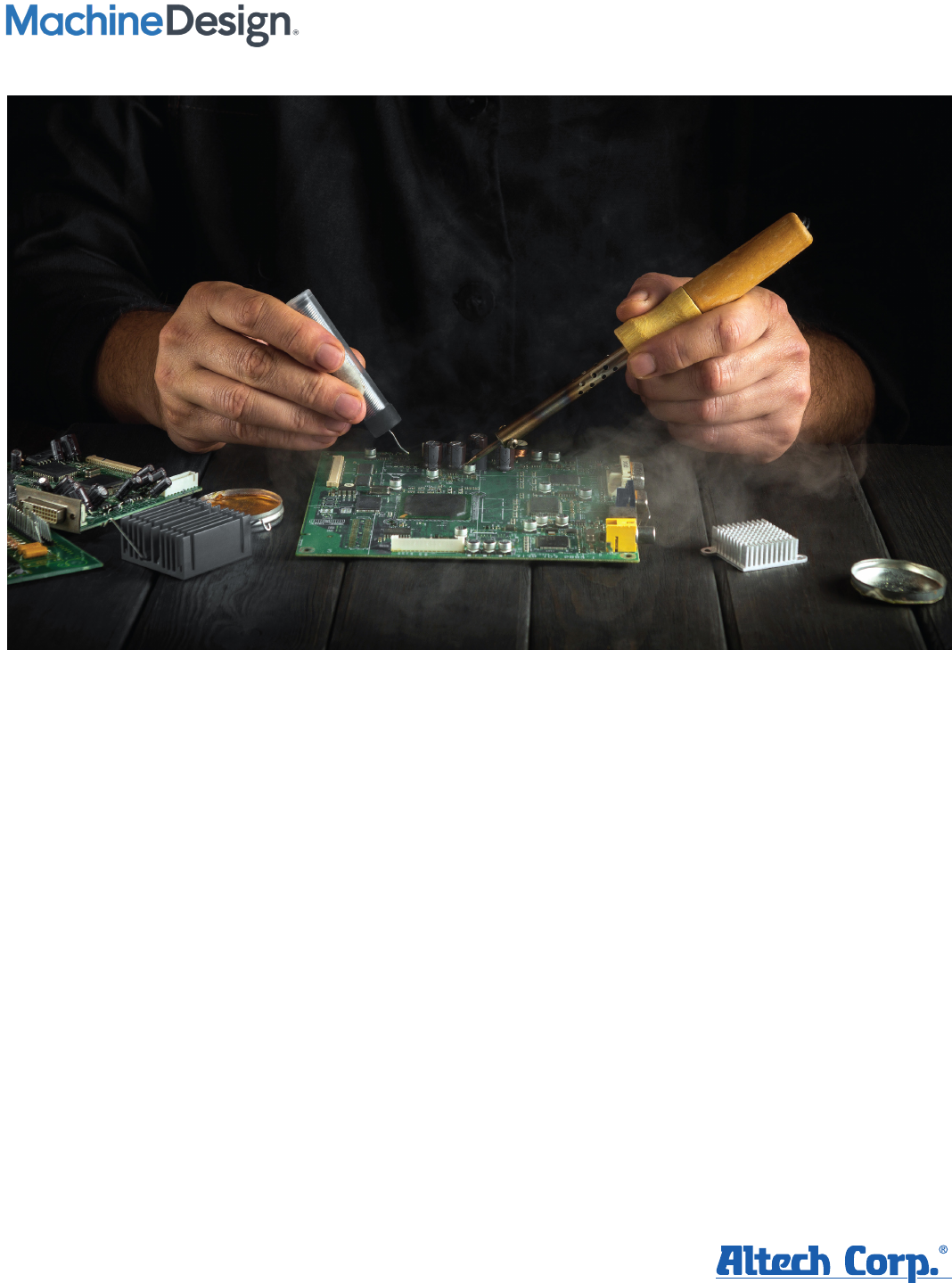
Figure 8: Besides automated soldering solutions, manual soldering if oen necessary when a PCB component needs to be
replaced.
