
TRF No.: IEC 61010_H Page 1 of 123 TRF originator: VDE
MS-0005049_en Revision 1
Test Report issued under the responsibility of:
TEST REPORT
IEC 61010-1: 2010
Safety requirements for electrical equipment for measurement, control, and laboratory use
Part 1: General requirements
Report Number. ................................ :
02072255.013
Date of issue ...................................... :
07/26/2013
Total number of pages ...................... :
123 Pages (including Attachments)
Applicant’s name .............................. :
SRI Instruments, Inc.
Address .............................................. :
6440 Sunset Corporation Drive, Las Vegas, NV 89120, USA
Test specification:
Standard ............................................. :
IEC 61010-1: 2010 (3
rd
Edition) / EN 61010-1: 2010 (3
rd
Edition)
UL 61010-1:2012, CAN/CSA-C22.2 No. 61010-1-12
Test procedure ................................... :
cTUVus
Non-standard test method .................. :
N/A
Test Report Form No. ...................... :
IEC61010_1H
TRF Originator ................................... :
VDE Testing and Certification Institute
Master TRF ........................................ :
2011-11
Copyright © 2011 Worldwide System for Conformity Testing and Certification of Electrotechnical Equip
ment
and Components (IECEE), Geneva, Switzerland. All rights reserved.
This publication may be reproduced in whole or in part for non-commercial purposes as long as the IECEE is acknowledged as copyright owner
and source of the material. IECEE takes no responsibility for and will not assume liability for damages resulting from the reader's interpretation
of the reproduced material due to its placement and context.
If this Test Report Form is used by non-IECEE members, the IECEE/IEC logo and the reference to the CB Scheme
procedure shall be removed.
This report is not valid as a CB Test Report unless signed by an approved CB Testing Laboratory and ap-
pended to a CB Test Certificate issued by an NCB in accordance with IECEE 02.
Test item description ....................... :
Gas Chromatography Systems
Trade Mark ......................................... :
Manufacturer ...................................... :
Same as Applicant
Model/Type Reference ....................... :
110, 310, 410, 8610C, 8610D, 8610V
Ratings ............................................... :
AC 115V, 50/60Hz, 1725VA

Report No.: 02072255.013
TRF No.: IEC 61010_H Page 2 of 123 TRF originator: VDE
MS-0005049_en Revision 1
Testing procedure and testing location:
CB Testing Laboratory:
TÜV Rheinland of North America Inc.
Testing location / address ............................:
12 Commerce Road
Newtown, CT 06470
Associated CB Laboratory:
Testing location/ address ..............................:
Tested by (name + signature) ......... : Ricardo Felix
Approved by (name + signature) .... : Uwe Meyer
Testing procedure: TMP
Testing location/ address ............................ :
Tested by (name + signature) ......... :
Approved by (name + signature) .... :
Testing procedure: WMT
Testing location / address ............................:
Tested by (name + signature) ......... :
Witnessed by (name + signature) ... :
Approved by (name + signature) .... :
Testing procedure: SMT
Testing location / address ............................:
Tested by (name + signature) ......... :
Approved by (name + signature) .... :
Supervised by (name + signature) .. :
Testing procedure: RMT
Testing location / address ............................:
Tested by (name + signature) ......... :
Approved by (name + signature) .... :
Supervised by (name + signature) .. :

Report No.: 02072255.013
TRF No.: IEC 61010_H Page 3 of 123 TRF originator: VDE
MS-0005049_en Revision 1
List of Attachments (including a total number of pages in each attachment):
Document No. Documents included / attached to this report (description)* Page
Numbers**
TABLE 1 List of safety relevant components 1
TABLE 2 List of test equipment used 1
ATTACHMENT 1
National Differences 22
ATTACHMENT 2
Photo-documentation 7
ATTACHMENT 3
Transformer Schematic and Specificatins 9
*Attachments located at the end of this report.
**Number of pages for each document indicated instead
Summary of testing:
The product fulfils the requirements of IEC 61010-1:2010 [3
rd
Edition] and EN 61010-1: 2010 (3
rd
Edition),
as well as of UL 61010-1:2012 and CAN/CSA-C22.2 No. 61010-1-12
Test Report History:
This report may consist of more than one report and is valid only with additional or previous issued reports:
Ref. No.: 02072255.011 Item
Tests performed (name of test and test clause): Testing location:
All testing indicated below was performed as part of the
original evaluation according to report number
02072255.011, no additional testing was performed for
this upgrade of standard.
TÜV Rheinland of North America Inc.
12 Commerce Road
Newtown, CT 06470
4.4: Single Fault Condition
5.1.3 c): Inputs
5.3: Durability of Markings
6.3.1 Permissible Limits of Accessible Parts:
Normal Condition
6.3.2 Permissible Limits of Accessible Parts:
Single Fault Condition
6.5.2.3 Tighting torque test
6.5.2.4 Bonding Impedance
6.7.1 Clearance and Creepage Distances
6.8 Dielectric Strength
6.10.2 Cord anchorage test
6.10.3 Capacitance Discharge
10.1.3/.3 Temperature Measurements

Report No.: 02072255.013
TRF No.: IEC 61010_H Page 4 of 123 TRF originator: VDE
MS-0005049_en Revision 1
Summary of compliance with National Differences:
List of countries addressed: All EC countries are covered by the report. National Differences
for Canada and United
States are addressed in Attachment 1.
Copy of marking plate:
The artwork below may be only a draft. The use of certification marks on a product must be authorized by the re-
spective NCBs that own these marks.
[check box used for the actual rating and market]

Report No.: 02072255.013
TRF No.: IEC 61010_H Page 5 of 123 TRF originator: VDE
MS-0005049_en Revision 1
Test item particulars ......................................... :
Type of item ........................................................ :
Measurement / Control / Laboratory
Description of equipment function ...................... :
See ‘General Product Description’ below
Connection to MAINS supply ................................ : Permanent / Detachable Cord Set / Non De
tachable Cord
Set / None
Overvoltage category .......................................... :
II
POLLUTION DEGREE ............................................. :
2
Means of protection ............................................ : Class I (PE connected) / Class II (isolated)
Environmental rating ........................................... :
Normal / Extended (Specify):
Equipment mobility .............................................. :
Portable / Hand-held / Floor-standing / Fixed / Built in
Operating conditions ........................................... : Continuous / Short-time / Intermittent
Overall size of the equipment (W x D x H) ......... : 110: 216mm x 343mm x 368 mm
410, 8610C, 8610D, 8610V: 200mm x 350mm x 430mm
310: 317mm x 343mm x 368 mm
Mass of the equipment (kg) ................................ :
<18
Marked degree of protection to IEC 60529 ........ :
IPX0
Possible test case verdicts:
– test case does not apply to the test object ...... : N/A
– test object does meet the requirement ............ : P (Pass)
– test object does not meet the requirement ...... : F (Fail)
Testing
Date of receipt of test item .................................. : 09/04/2012
Date (s) of performance of tests ......................... : 09/07/2012 – 09/17/2012
General remarks:
The test results presented in this report relate only to the object tested.
This report shall not be reproduced, except in full, without the written approval of the Issuing testing laboratory.
"(See Attachment #)" refers to additional information appended to the report.
"(See Form A.xx)" refers to a table appended to the report.
Throughout this report a comma / point is used as the decimal separator.
Manufacturer’s Declaration per sub-clause 6.2.5 of IECEE 02:
The application for obtaining a CB Test Certificate includes more than one
factory location and a declaration from the Manufacturer stating that the
sample(s) submitted for evaluation is (are) representative of the products
from each factory has been provided ............................................................... :
Yes Not Applicable
When differences exist; they shall be identified in the General product information section.
Name and address of factory (ies) ................ :
SRI Instruments, Inc.
6440 Sunset Corporation Drive, Las Vegas, NV 89120, USA

Report No.: 02072255.013
TRF No.: IEC 61010_H Page 6 of 123 TRF originator: VDE
MS-0005049_en Revision 1
General product information:
The Chromatography series consist of the following models: 110, 310, 410, 8610C, 8610D, 8610V. These Gas
Chromatographs and data systems are used in laboratory environment to detect and analyze gases. The power rat-
ing is a maximum value based on the maximum amount of heaters installed.
Model number 8610C was selected for all testing herein as it represents the maximum configuration of models.
An optional vacuum pump can be connected to the Gas Chromatographs, however such pump was connected to
the optional AC-outlet for testing purpose but it has not been part of the investigation.
The maximum operating ambient temperature is rated with 40˚C.
There are no parts or materials that are frequently touched and held for a longer period of time. There-fore no parts
or materials are relevant for PAH evaluation.

Report No.: 02072255.013
IEC 61010-1 and/or EN 61010-1
Clause Requirement – Test Result – Remark Verdict
TRF No.: IEC 61010_H Page 7 of 123 TRF originator: VDE
MS-0005049_en Revision 1
4.4 TESTING IN SINGLE FAULT CONDITIONS
P
4.4.1 Fault tests See Form A.1 and A.2 P
4.4.2 Application of SINGLE FAULT CONDITIONS P
4.4.2.1 SINGLE FAULT CONDITIONS not covered by 4.4.2.1 to
4.4.2.14
All covered by 4.4.2.1 to 4.4.2.12 N/A
4.4.2.2 PROTECTIVE IMPEDANCE None relied upon for safety N/A
4.4.2.3 PROTECTIVE CONDUCTOR See 6.3.2 P
4.4.2.4 Equipment or parts for short-term or intermittent
operation
Continuous operation N/A
4.4.2.5 Motors Certified fans used
Motor was tested, refer to Form A.1
P
– stopped while fully energized
See above P
– prevented from starting
See above P
– one phase interrupted (multi-phase)
See above P
4.4.2.6 Capacitors No capacitors provided within auxiliary
windings or AC motor
N/A
4.4.2.7 MAINS transformers Mains transformer has been tested
within appliance. Same transformer is
used for 115V and 230V-version but
different wiring to accommodate volt-
age. Transformer is wired in produc-
tion.
P
4.4.2.7.2 Short circuit
(see Forms A.39)
P
4.4.2.7.3 Overload
(see Forms A.40)
P
4.4.2.8 Outputs AC outlet for Vacuum pump is protect-
ed by one fuse in phase and has been
properly tested, Form A.1 and A.2
P
4.4.2.9 Equipment for more than one supply Single supply per unit N/A
4.4.2.10 Cooling (see Form A.26A)
Blocked vents and locked fan rotor
P
– air holes closed
P
– fans stopped
P
– coolant stopped
No coolant N/A
– loss of cooling liquid
See above N/A
4.4.2.11 Heating devices Heating devices have been properly
evaluated and tested within application,
see Form A.1 and A.2
P
– timer overridden
No timer N/A

Report No.: 02072255.013
IEC 61010-1 and/or EN 61010-1
Clause Requirement – Test Result – Remark Verdict
TRF No.: IEC 61010_H Page 8 of 123 TRF originator: VDE
MS-0005049_en Revision 1
– temperature controller overridden
No temperature control used where
safety is relied upon
[Temperature control:
600W heater at top, thermocouple with
feedback loop, 0-crossing triac, getting
close to the set-up it flickers at 34Hz. ->
feels open save, fails close, supervi-sory
circuit thermocouple 425degC]
N/A
4.4.2.12 Insulation between circuits and parts Circuits comply with par. 9.1 P
4.4.2.13 Interlocks Interlock is used for functional purpos-
es only, no further evaluation or testing
deemed necessary
N/A
4.4.2.14 Voltage selectors Two voltage settings possible, the
transformer is wired internally for the
correct voltage, the corresponding rat-
ing and certification mark for the actual
setting is guaranteed at manufacturing
site, no further testing deemed neces-
sary.
N/A
4.4.3 Duration of tests (see Form A.1) —
4.4.4 Conformity after application of fault conditions (see Form A.1; A.6, A.18) P
5 MARKING AND DOCUMENTATION
P
5.1.1 General P
Required equipment markings —
- Visible from the exterior; or
Markings are visible from the exterior
or when the lid / main cover is opened,
see below
P
- Visible after removing cover or opening door
Additional warning symbols are visible
once enclosure to main compartments
is opened
(ISO 3864 No. B3.1)
No doors
N/A
- Visible after removal from a rack or panel
Not so mounted in intended use N/A
Not put on parts which can be removed by an
operator
Safety related markings are not put on
parts which can be removed by an
OPERATOR
P
Letter symbols (IEC 60027) used
V, HZ, VA P
Graphic symbols (IEC 61010-1: Table 1) used
Comply with Table 1 P
5.1.2 Identification —
Equipment is identified by: P

Report No.: 02072255.013
IEC 61010-1 and/or EN 61010-1
Clause Requirement – Test Result – Remark Verdict
TRF No.: IEC 61010_H Page 9 of 123 TRF originator: VDE
MS-0005049_en Revision 1
a) Manufacturer’s or supplier’s name or trademark
P
b) Model number, name or other means Chromatograph Family, specific model
number clearly identified on units
P
Manufacturing location identified Single manufacturing location N/A
5.1.3 MAINS supply See below P
Equipment is marked as follows: P
a) Nature of supply: —
1) a.c. RATED MAINS frequency or range of
frequencies .................................................. :
RATED MAINS frequency 50/60Hz is pro-
vided on label
P
2) d.c. with symbol 1 AC powered equipment N/A
b) RATED supply voltage(s) or range ....................... :
AC 115V (North America configuration)
AC 230V (European configuration)
P
c) Max. RATED power (W or VA) or input current ... :
1725VA P
The marked value not less than 90 % of the
maximum value
The measured power consumption
value was less than rated power (see
Form A.3)
P
If more than one voltage range: —
Separate values marked; or No voltage range but two voltage set-
tings possible, transformer is wired in-
ternally for the correct voltage, the cor-
responding rating and certification
mark for the actual setting is guaran-
teed.
P
Values differ by less than 20 % See above, requirement does not apply N/A
d) OPERATOR-set for different RATED supply volt-
ages:
—
Indicates the equipment set voltage No such operator setting N/A
PORTABLE EQUIPMENT indication is visible from
the exterior
No such operator setting N/A
Changing the setting changes the indication No such operator setting N/A
e) Accessory MAINS socket-outlets accepting
standard
MAINS plugs are marked:
—
With the voltage if it is different from the MAINS
supply voltage .................................................... :
IEC60320 mains plug is referenced ad-
jacent to the outlet, description of volt-
age and max. current rating provided
P
For use only with specific equipment Provided on label adjacent to outlet P
If not marked for specific equipment it is
marked with:
P

Report No.: 02072255.013
IEC 61010-1 and/or EN 61010-1
Clause Requirement – Test Result – Remark Verdict
TRF No.: IEC 61010_H Page 10 of 123 TRF originator: VDE
MS-0005049_en Revision 1
The maximum RATED current or power; or See above P
Symbol 14 with full details in the documentation No further symbol necessary N/A
5.1.4 Fuses N/A
OPERATOR replaceable fuse marking (see also
5.4.5) ........................................................................ :
Non-operator-replaceable circuit
breakers and fuses provided
N/A
5.1.5 TERMINALS, connections and operating devices See below P
5.1.5.1 General —
Where necessary for safety, indication of purpose
of
TERMINALS, connectors, controls and indicators
marked
Connectors are marked with indication
of purpose
P
If insufficient space, symbol 14 used Not required N/A
Push-buttons and actuators of emergency stop
devices and indicators:
See above
—
used only to indicate a warning of danger or
See above N/A
the need for urgent action
See above N/A
coloured red
See above N/A
coded as specified in IEC 60073
See above N/A
Supplementary means of coding provided, if
meaning of colour relates (see IEC 60073):
See above N/A
to safety of persons; or
See above N/A
safety of the environment
See above N/A
5.1.5.2 TERMINALS See below P
MAINS supply TERMINALS identified Non-detachable mains cord provided.
Internal terminals provided as part of
circuit breaker and EMI filter, used for
the internal distribution of mains power.
No further marking deemed necessary
P
Other TERMINAL marking ........................................... :
See below P
a) FUNCTIONAL EARTH TERMINALS (symbol 5 used) No functional earth N/A
b) PROTECTIVE CONDUCTOR TERMINALS: See below P
Symbol 6 is placed close to or on the TERMINAL;
or
Provided P
Part of appliance inlet No appliance inlet N/A
c) TERMINALS of control circuits (symbol 7 used) No measuring and control circuits
which are in the scope of this standard
N/A
d) HAZARDOUS LIVE TERMINALS supplied from the
interior
Auxiliary AC outlet for the vacuum
pump is properly marked
P
Standard MAINS socket outlet; or None provided N/A

Report No.: 02072255.013
IEC 61010-1 and/or EN 61010-1
Clause Requirement – Test Result – Remark Verdict
TRF No.: IEC 61010_H Page 11 of 123 TRF originator: VDE
MS-0005049_en Revision 1
RATINGS marked; or Auxiliary AC output for the vacuum
pump is properly marked
P
Symbol 14 used See above N/A
5.1.6 Switches and circuit breakers See below N/A
If disconnecting device, off position clearly marked Plug on power cord is regarded as dis-
connecting device. Nevertheless,
mains switch is marked with symbols 9
and 10.
P
If push-button used as power supply switch:
Push-button not used as power supply
switch.
N/A
Symbol 9 and 15 used for on-position
See above N/A
Symbol 10 and 16 used for off-position
See above N/A
Pair of symbols 9, 15 and 10, 16 close together
See above N/A
5.1.7 Equipment protected by DOUBLE INSULATION or
REINFORCED INSULATION
See below P
Protected throughout (symbol 11 used) Not Class II equipment N/A
Only partially protected (symbol 11 not used) Only partially protected for accessible
conductive parts not connected to pro-
tective earth (symbol 11 not used)
P
5.1.8 Field-wiring TERMINAL boxes No field wiring terminal boxes N/A
If
TERMINAL or ENCLOSURE exceeds 60 °C:
See below N/A
Cable temperature RATING marked ........................ : See above N/A
Marking visible before and during connection or be-
side
TERMINAL
See above N/A
5.2 Warning markings See above P
Visible when ready for NORMAL USE
Symbol
provided on cover. As
well as hot surface symbol IEC 417 No.
5041 on the upper enclosure and other
internal parts; all warning markings for
hot surface were found adequate for
the product and application in question
P
Are near or on applicable parts See above P
Symbols and text correct dimensions and colour: See above —
a) symbols min 2,75 mm and text 1,5 mm high
and contrasting in colour with background
Proper size used P
b) symbols and text moulded, stamped or
engraved in material min. 2,0 mm high and
Separate labels used on the product P
0.5 mm depth or raised if not contrasting in
colour
See above P

Report No.: 02072255.013
IEC 61010-1 and/or EN 61010-1
Clause Requirement – Test Result – Remark Verdict
TRF No.: IEC 61010_H Page 12 of 123 TRF originator: VDE
MS-0005049_en Revision 1
If necessary marked with symbol 14 See above P
Statement to isolate or disconnect if access by us-
ing a tool to
HAZARDOUS LIVE parts is permitted
No operator accessible parts at haz-
ardous live
N/A
5.3 Durability of markings P
The required markings remain clear and legible in
NORMAL USE
The required markings remain clear
and legible in NORMAL USE (see Form
A.3)
P
5.4 Documentation See below P
5.4.1 General See below P
Equipment is accompanied by documentation for
safety purposes for
OPERATOR or RESPONSIBLE
BODY
Operating instructions are all available
online depending upon configuration of
the actual gas chromatography system
P
Safety documentation for service personnel author-
ized by the manufacturer
See above P
Documentation necessary for safe operation is pro-
vided in printed media or
See above P
in electronic media if available at any time P
Documentation includes: —
a) Intended use Provided in user manual (operating in-
structions)
P
b) Technical specification Provided in user manual P
c) Name and address of manufacturer or supplier Provided in user manual and on prod-
uct
P
d) Information specified in 5.4.2 to 5.4.6 See below clause 5.4.2 P
e) Information to mitigate residual RISK
(see also subclause 17)
P
f) Accessories for safe operation of the equip-
ment specified
Sufficient information provided in in-
structions
P
g) Guidance provided to check correct function of
the equipment, if incorrect reading may cause a
HAZARD from harmful or corrosive substances
or
HAZARDOUS live parts
No such equipment which needs fur-
ther instructions or guidance to check
correction function the equipment
N/A
h) Instructions for lifting and carrying No handle or grips N/A
Warning statements and a clear explanation of
warning symbols:
—
Provided in the documentation; or Not measuring equipment N/A
Information is marked on the equipment Not measuring equipment N/A
5.4.2 Equipment RATINGS See below P
Documentation includes: —

Report No.: 02072255.013
IEC 61010-1 and/or EN 61010-1
Clause Requirement – Test Result – Remark Verdict
TRF No.: IEC 61010_H Page 13 of 123 TRF originator: VDE
MS-0005049_en Revision 1
a) Supply voltage or voltage range ........................ :
AC 115 (NRTL)
AC 230 (GS)
P
Frequency or frequency range ........................... :
50/60Hz P
Power or current RATING .................................... :
1725VA P
b) Description of all input and output connections
in accordance to 6.6.1 a)
Description of all connections provided
in user manual and on product
P
c) RATING of insulation of external circuits in ac-
cordance to 6.6.1 b)
No special insulation is required: exter-
nal circuits are SELV except for auxilia-
ry AC outlet for vacuum pump which is
not considered as such
N/A
d) Statement of the range of environmental condi-
tions (see 1.4)
Provided in manual:
Indoor use (defined as laboratory
benchtop device)
Altitude up to 2500m
Temperature 10ºC to 40ºC
Maximum relative humidity 80% (non-
condensing)
MAINS supply voltage fluctuations up
to ±10% of the nominal voltage
Transient over voltages Over voltage
Category II
NOTE: The nominal level of transient
over voltages is impulse withstand
(over voltage) category II of IEC 60364-
4-44
Applicable Pollution Degree II
P
e) Degree of protection (IEC 60529) Not required: IPX10 N/A
f) If impact rating less than 5 J: Metal enclosure, not less than 5 J —
IK code in accordance to IEC 62262 marked or
N/A
symbol 14 of table 1 marked, with
N/A
RATED energy level and test method stated
N/A
5.4.3 Equipment installation See below P
Documentation includes instructions for: —
a) Assembly, location and mounting requirements Provided in user manual P
b) Protective earthing Instruction to connect equipment to
earthed socket outlet only provided in
manual
P
c) Connections to supply No special instructions required N/A
d) PERMANENTLY CONNECTED EQUIPMENT: See below N/A

Report No.: 02072255.013
IEC 61010-1 and/or EN 61010-1
Clause Requirement – Test Result – Remark Verdict
TRF No.: IEC 61010_H Page 14 of 123 TRF originator: VDE
MS-0005049_en Revision 1
1) Supply wiring requirements Not PERMANENTLY CONNECTED
EQUIPMENT
N/A
2) If external switch or circuit-breaker, re-
quirements and location recommendation
Not PERMANENTLY CONNECTED
EQUIPMENT
N/A
e) Ventilation requirements No special requirements N/A
f) Special services (e.g. air, cooling liquid) No special requirements N/A
g) Instructions relating to sound level Not required: equipment does not pro-
duce considerable amount of sound.
N/A
5.4.4 Equipment operation See below P
Instructions for use include:
a) Identification and description of operating con-
trols
None affecting safety other than for
ON/OFF switch marked “I/O” as evi-
dent
N/A
b) Positioning for disconnection Instruction not to position equipment so
that it is difficult to operate the dis-
counting device (appliance coupler) is
provided on label, see page 4
P
c) Instructions for interconnection Connection of computer via standard
signal cables (e.g. USB) is properly de-
scribed in the manual
P
d) Specification of intermittent operation limits No such limits N/A
e) Explanation of symbols used Provided in user manual P
f) Replacement of consumable materials No consumable materials P
g) Cleaning and decontamination
Minimal cleaning required which has no
safety relevant impact
P
h) Listing of any poisonous or injurious gases and
quantities
No poisonous or injurious gases N/A
i) RISK reduction procedures relating to flamma-
ble liquids (see 9.5)
No flammable liquids
(hydrogen gas has been considered)
N/A
j) RISK reduction procedures relating burn from
surfaces permitted to exceed limits of 10.1
Proper warnings and labels are provid-
ed on the equipment, see photographs
P
Additional precautions for IEC 60950 conforming
equipment in regard to moistures and liquids
Product not considered ‘IEC60950 con-
forming equipment’
N/A
A statement about protection impairment if used in
a manner not specified by the manufacturer
Provided in user manual P
5.4.5 Equipment maintenance and service See below P
Instructions for RESPONSIBLE BODY include: —
Instructions sufficient in detail permitting safe
maintenance and inspection and continued safety:
Provided in user manual P

Report No.: 02072255.013
IEC 61010-1 and/or EN 61010-1
Clause Requirement – Test Result – Remark Verdict
TRF No.: IEC 61010_H Page 15 of 123 TRF originator: VDE
MS-0005049_en Revision 1
Instruction against the use of detachable MAINS
supply cord with inadequate rating
No detachable power cord N/A
Specific battery type of user replaceable batteries No batteries N/A
Any manufacturer specified parts Instructions provided in the user man-
ual
P
Rating and characteristics of fuses Replaceable fuse for power outlet is
properly described on fuse holder, ad-
jacent to AC-outlet
P
Instructions include following subjects permitting safe
servicing and continued safety:
Servicing of the product is done by the
manufacturer
P
a) Product specific RISKS may affect service
personnel
No such additional risks which may af-
fect service personnel
N/A
b) Protective measures for these RISKS See above N/A
c) Verification of the safe state after repair See above, safe state after repair is
guaranteed by hipot and ground conti-
nuity test.
P
5.4.6
Integration into systems or effects resulting from
special conditions
No such integration into systems or
other special conditions
N/A
Aspects described in documentation
See above N/A
6 PROTECTION AGAINST ELECTRIC SHOCK P
6.1 General (see Form A.4 and A.5) P
6.1.1 Requirements —
Protection against electric shock maintained in
NORMAL CONDITION and SINGLE FAULT CONDITION
See clause 6.4 and 6.5 P
ACCESSIBLE parts not HAZARDOUS LIVE
ACCESSIBLE parts not HAZARDOUS LIVE in
NORMAL CONDITION and SINGLE FAULT
CONDITION
P
Voltage, current, charge or energy below the limits in
NORMAL CONDITION and in SINGLE FAULT CONDITION
between:
See clause 6.3.1 and 6.3.2 P
ACCESSIBLE parts and earth
See above P
Two
ACCESSIBLE parts on same piece of the
equipment within a distance of 1,8 m
See above P
Conformity is checked by the determination of 6.2
and 6.3 followed by the tests of 6.4 to 6.11
Considerations applied P
6.1.2 Exceptions No exceptions applied N/A
Following
HAZARDOUS LIVE parts may be accessible
to an
OPERATOR:
See above N/A

Report No.: 02072255.013
IEC 61010-1 and/or EN 61010-1
Clause Requirement – Test Result – Remark Verdict
TRF No.: IEC 61010_H Page 16 of 123 TRF originator: VDE
MS-0005049_en Revision 1
a) parts of lamps and lamp sockets after lamp
removal
See above N/A
b) parts to be replaced by operator only by the use
of tool and warning marking
See above N/A
Those parts not HAZARDOUS LIVE 10 s after interrup-
tion of supply
See above
N/A
Capacitance test if charge is received from internal
capacitor
See above
N/A
6.2 Determination of ACCESSIBLE parts
See below
P
6.2.1 General No access to hazardous parts with
jointed test finger applied with force
10N (see Form A.6)
P
Unless obviously determination of accessible parts
as specified in 6.2.2 to 6.2.4
See above —
6.2.2 Examination —
- with jointed test finger (as specified B.2)
See below P
- with rigid test finger (as specified B.1) and a force
of 10 N
No access to hazardous parts with
jointed test finger applied with force
10N (see Form A.4)
P
6.2.3 Openings above parts that are HAZARDOUS LIVE No such openings N/A
- test pin with length of 100 mm and 4 mm in diame-
ter applied
6.2.4 Openings for pre-set controls No such openings N/A
- test pin with length of 100 mm and 3 mm in diame-
ter applied
6.3 Limit values for ACCESSIBLE parts See below P
6.3.1 Levels in NORMAL CONDITION Values in NORMAL CONDITION NOT
EXCEEDED
(SEE FORM A.5)
P
a) Voltage limits less than 33 V r.m.s. and 46,7 V
peak or 70 V d.c.
See above P
for wet locations voltage limits less than 16 V
r.m.s. and 22,6 V peak or 35 V d.c.
Not intended for wet locations N/A
Voltages are not
HAZARDOUS LIVE the levels of:
—
b) Current less than 0,5 mA r.m.s. for sinusoidal,
0,7 mA peak non sinusoidal or mixed
frequencies or 2 mA d.c. when measured with
measuring circuit A.1 or A.2 if less than 100 Hz
See 6.3.1 above P
for WET LOCATIONS measuring circuit A.4 used Not intended for wet locations N/A
or ̶

Report No.: 02072255.013
IEC 61010-1 and/or EN 61010-1
Clause Requirement – Test Result – Remark Verdict
TRF No.: IEC 61010_H Page 17 of 123 TRF originator: VDE
MS-0005049_en Revision 1
c) Levels of capacitive charge or energy less: No such energies or charges meas-
ured
N/A
1) 45 µC for voltages up to 15 kV peak or d.c. or
line A of Figure 3
See above N/A
2) 350 mJ stored energy for voltages above 15
kV peak or d.c.
See above N/A
6.3.2 Levels in SINGLE FAULT CONDITION Values in SINGLE FAULT CONDITION not
exceeded (see Form A.6)
P
a) Voltage limits less than 55 V r.m.s. and 78 V
peak or 140 V d.c.
See above P
for WET LOCATIONS voltage limits less than 33 V
r.m.s. and 46,7 V peak or 70 V d.c.
Not intended for wet locations N/A
Voltages are not
HAZARDOUS LIVE the levels of:
—
b) Current less than 3,5 mA r.m.s. for sinusoidal, 5
mA peak non sinusoidal or mixed frequencies or
15 mA d.c. when measured with measuring
circuit A.1 or A.2 if less than 100 Hz
See 6.3.2 above P
for wet locations measuring circuit A.4 used Not intended for wet locations N/A
500 mA r.m.s. when measured with circuit A.3 for
higher frequencies
See above N/A
or —
c) Levels of capacitive charge or energy less line B
of Figure 3
No such energies or charges meas-
ured
N/A
6.4 Primary means of protection (see 6.2, 6.3.1, 6.7, 6.8 and 8.1) P
6.4.1 ACCESSIBLE parts prevented from being HAZARDOUS
LIVE by one or more of following means:
P
a) ENCLOSURES or PROTECTIVE BARRIERS (see 6.4.2) Considerations of b) applied N/A
b) BASIC INSULATION (see 6.4.3) Provided by Basic insulation between
hazardous parts and accessible parts
connected to protective earth
P
c) Impedance (see 6.4.4) Considerations of b) applied N/A
6.4.2 ENCLOSURES or PROTECTIVE BARRIERS Metal enclosure used
(see Form A.15)
P
- meet rigidity requirements of 8.1 See clause 8.1 P
- meet requirements for BASIC INSULATION, if protec-
tion is provided by insulation
Rigid metal enclosure provided P
- meet requirements of 6.7 for CREEPAGE and
CLEARANCES between ACCESSIBLE parts and
HAZARDOUS live parts, if protection is provided by lim-
ited access
See clause 6.7 P
6.4.3 BASIC INSULATION (see Form A.15) P

Report No.: 02072255.013
IEC 61010-1 and/or EN 61010-1
Clause Requirement – Test Result – Remark Verdict
TRF No.: IEC 61010_H Page 18 of 123 TRF originator: VDE
MS-0005049_en Revision 1
- meet CLEARANCE, CREEPAGE DISTANCE and solid in-
sulation requirements of 6.7
P
6.4.4 Impedance No protective impedance N/A
Impedance used as primary means of protection
meets all of following requirements:
N/A
a) limits current or voltage to level of 6.3.2 (see Form A.6) N/A
b) RATED for maximum WORKING VOLTAGE and the
amount of power it will dissipate
N/A
c) CLEARANCE, CREEPAGE DISTANCE between
terminations of the impedance meet
requirements of
BASIC INSULATION of 6.7
(see Form A.15) N/A
6.5 Additional means of protection in case of SINGLE FAULT CONDITION P
6.5.1 ACCESSIBLE parts are prevented from becoming
HAZARDOUS live by the primary means of protection
and supplemented by one of:
—
a) PROTECTIVE BONDING (see 6.5.2) Connection to PE terminal relied upon P
b) SUPPLEMENTARY INSULATION (see 6.5.3) Not Used N/A
c) automatic disconnection of the supply (see
6.5.5)
Not Used N/A
d) current- or voltage-limiting device (see 6.5.6) Not Used N/A
Alternatively one of the single means of protection is
used:
P
e) REINFORCED INSULATION (see 6.5.3) Double insulation or reinforced insula-
tion between mains and SELV main-
tained within isolation transformer pro-
vided with UL Recognized insulation
system (See Separate Construction
Data Form)
P
f) PROTECTIVE IMPEDANCE (see 6.5.4) Double insulation or reinforced insula-
tion between mains and SELV main-
tained within isolation transformer pro-
vided with UL Recognized insulation
system (See Separate Construction
Data Form)
P
6.5.2 PROTECTIVE BONDING (see Forms A.7, A.8, A.9, A.10 or A.11) —
6.5.2.1 ACCESSIBLE conductive parts, may become
HARZARDOUS LIVE in SINGLE FAULT CONDITION:
—
Bonded to the PROTECTIVE CONDUCTOR TERMINAL; or ACCESSIBLE conductive parts bonded to
the
PROTECTIVE CONDUCTOR TERMINAL
P
Separated by conductive screen or barrier bonded to
PROTECTIVE CONDUCTOR TERMINAL
Not used N/A
6.5.2.2 Integrity of PROTECTIVE BONDING See below P

Report No.: 02072255.013
IEC 61010-1 and/or EN 61010-1
Clause Requirement – Test Result – Remark Verdict
TRF No.: IEC 61010_H Page 19 of 123 TRF originator: VDE
MS-0005049_en Revision 1
a) PROTECTIVE BONDING consists of directly con-
nected structural parts or discrete conductors
or both; and withstands thermal and dynamic
stresses
PROTECTIVE BONDING consists of direct-
ly connected structural parts or discrete
conductors or both; and withstands
thermal and dynamic stresses
P
b) Soldered connections: Soldered connections are not used for
bonding
N/A
Independently secured against loosening See above N/A
Not used for other purposes See above N/A
c) Screw connections are secured See above N/A
d) PROTECTIVE BONDING not interrupted; or No operator-removable parts providing
ground continuity other than plug on
power cord used as disconnect device,
AC outlet for vacuum pump not con-
sidered as such
N/A
exempted as removable part carries MAINS SUPPLY
INPUT
connection
See above N/A
e) Any moveable PROTECTIVE BONDING connection
specifically designed, and meets 6.5.2.4
No moveable connections N/A
f) No external metal braid of cables used
(not regarded as
PROTECTIVE BONDING)
No external metal braid of cables used P
g) If MAINS supply passes through: Mains is properly passing through the
equipment and is reliably fixed on AC-
outlet
P
Means provided for passing protective conduc-
tor;
See above, protective conductor in-
spected and tested
P
Impedance meets 6.5.2.4 See above P
h) Protective conductors bare or insulated,
if insulated, green/yellow
Green/yellow used for protective con-
ductors
P
Exceptions: —
1) earthing braids; No earthing braids used N/A
2) internal protective conductors etc.; Terminal meets 6.5.2.3 P
Green/yellow not used for other purposes Green/yellow not used for purposes
other than bonding
P
TERMINAL suitable for connection of a PROTECTIVE
CONDUCTOR, and meets 6.5.2.3
Terminal meets 6.5.2.3 P
6.5.2.3 PROTECTIVE CONDUCTOR TERMINAL See below P
a) Contact surfaces are metal Contact surfaces are metal P
b) Appliance inlet used Non-detachable power cord used N/A

Report No.: 02072255.013
IEC 61010-1 and/or EN 61010-1
Clause Requirement – Test Result – Remark Verdict
TRF No.: IEC 61010_H Page 20 of 123 TRF originator: VDE
MS-0005049_en Revision 1
c) For rewireable cords and PERMANENTLY
CONNECTED EQUIPMENT
, PROTECTIVE
CONDUCTOR TERMINAL
is close to MAINS supply
TERMINALS
No rewireable cords and not
PERMANENTLY CONNECTED EQUIPMENT
N/A
d) If no MAINS supply is required, any PROTECTIVE
CONDUCTOR TERMINAL
:
Protective conductor terminal is re-
quired only for mains supply
N/A
Is near TERMINALS of circuit for which protective
earthing is necessary
See above N/A
External if other TERMINALS external See above N/A
e) Equivalent current-carrying capacity to MAINS
supply
TERMINALS
By inspection of power cord related
adequately for application
P
f) If plug-in, makes first and breaks last By inspection P
g) If also used for other bonding purposes,
PROTECTIVE CONDUCTOR:
Not used for other bonding purposes N/A
Applied first; See above N/A
Secured independently; See above N/A
Unlikely to be removed by servicing See above N/A
h) PROTECTIVE CONDUCTOR of measuring circuit: No measuring circuit provided N/A
1) Current RATING equivalent to measuring cir-
cuit
TERMINAL;
See above N/A
2) PROTECTIVE BONDING: See above N/A
Not interrupted See above N/A
i) FUNCTIONAL EARTH TERMINALS allow independ-
ent connection
No functional earth connection N/A
j) If a binding screw used for PROTECTIVE
CONDUCTOR TERMINAL
:
No binding screw N/A
Suitable size for bond wire By inspection P
Not smaller than M 4 (No. 6) By inspection P
At least 3 turns of screw engaged By inspection P
Passes tightening torque test See Form A.8 P
k) Contact pressure not capable being reduced by
deformation of materials
By inspection P
6.5.2.4 Impedance of PROTECTIVE BONDING of plug-
connected equipment
Impedance does not exceed 0.1 Ω
(see Form A.9)
P
Impedance between PROTECTIVE CONDUCTOR
TERMINAL and each ACCESSIBLE part where
PROTECTIVE BONDING is specified, is:
—
less than 0,1 Ohm; or See above P

Report No.: 02072255.013
IEC 61010-1 and/or EN 61010-1
Clause Requirement – Test Result – Remark Verdict
TRF No.: IEC 61010_H Page 21 of 123 TRF originator: VDE
MS-0005049_en Revision 1
less than 0,2 Ohm if equipment is provided with
non detachable cord
See above P
6.5.2.5 Bonding impedance of PERMANENTLY CONNECTED
EQUIPMENT
No
PERMANENTLY CONNECTED
EQUIPMENT
N/A
6.5.2.6 Transformer PROTECTIVE BONDING screen (see Form A.11) N/A
Transformer provided with screen for protective
bonding:
No such screen provided N/A
screen bonding consists of directly connected
structural parts or discrete conductors or both;
and withstands thermal and dynamic stresses
(see 6.5.2.2 a)
N/A
screen bonding with soldered connection (see
6.5.2.2 b) is:
N/A
- Independently secured against loosening
N/A
- Not used for other purposes
N/A
6.5.3 SUPPLEMENTARY and REINFORCED INSULATION Double insulation or reinforced insula-
tion between mains and SELV main-
tained within isolation transformer pro-
vided with UL Recognized insulation
system (See Separate Construction
Data Form)
P
Meet CLEARANCE, CREEPAGE DISTANCE and solid in-
sulation requirements of 6.7
(See table A.15) P
6.5.4 PROTECTIVE IMPEDANCE PROTECTIVE IMPEDANCE not used N/A
Limits current or voltage to level of 6.3.1 in NORMAL
and to level of 6.3.2 in
SINGLE FAULT CONDITION
See above N/A
CLEARANCE, CREEPAGE DISTANCE between termina-
tions of the impedance meet requirements of
DOUBLE
or REINFORCED INSULATION of 6.7
See above N/A
The protective impedance consists of one or more of
the following:
—
a) appropriate single component suitable for safety
and reliability for protection, it is:
See above N/A
1) RATED twice the maximum WORKING VOLTAGE See above N/A
2) resistor RATED for twice the power dissipation
for maximum
WORKING VOLTAGE
See above N/A
b) combination of components See above N/A
Single electronic device not used as PROTECTIVE
IMPEDANCE
N/A
6.5.5 Automatic disconnection of the supply Automatic disconnection of the supply
is not used
N/A

Report No.: 02072255.013
IEC 61010-1 and/or EN 61010-1
Clause Requirement – Test Result – Remark Verdict
TRF No.: IEC 61010_H Page 22 of 123 TRF originator: VDE
MS-0005049_en Revision 1
a) RATED to disconnect the load within time speci-
fied in Figure 2
See above N/A
b) RATED for the maximum load conditions of the
equipment
See above N/A
6.5.6 Current- or voltage-limiting devices No such components used, input fuse is
not considered as such
(see Form A.13)
N/A
Device complies with all of: See above N/A
a) RATED to limit the current or voltage to the level
of 6.3.2
See above, (see Form A.6) N/A
b) RATED for the maximum working voltage; and See above N/A
RATED for the maximum operational current if
applicable
See above N/A
c) CLEARANCE, CREEPAGE DISTANCE between termi-
nations of the impedance meet requirements of
SUPPLEMENTARY INSULATION of 6.7
(see Form A.14, A.15) N/A
6.6 Connections to external circuits Automatic disconnection of the supply
is not used
N/A
6.6.1 Connections do not cause ACCESSIBLE parts of the
following to become
HAZARDOUS LIVE in NORMAL
CONDITION
or SINGLE FAULT CONDITION:
Inspected
Signal on signal port to external com-
puter is SELV
P
- the external circuits See above P
- the equipment See above P
Protection achieved by separation of circuits; or See above, separation guaranteed by
isolation transformer and proper insula-
tion on PCBs
P
Short circuit of separation does not cause a HAZARD See above P
Instructions or markings for each terminal include: No further instructions or markings N/A
a) RATED conditions for TERMINAL See above N/A
b) Required RATING of external circuit insula-
tion
See above N/A
6.6.2 TERMINALS for external circuits No such terminals N/A
TERMINALS which receive a charge from an internal
capacitor are not
HAZARDOUS LIVE after 10 s of inter-
rupting supply connection
See above N/A
6.6.3 Circuits with TERMINALS which are HAZARDOUS LIVE No such terminals provided, AC outlet
is a standard outlet for a vacuum pump
not considered as such
N/A
These circuits are: —
Not connected to ACCESSIBLE conductive parts; or See above N/A

Report No.: 02072255.013
IEC 61010-1 and/or EN 61010-1
Clause Requirement – Test Result – Remark Verdict
TRF No.: IEC 61010_H Page 23 of 123 TRF originator: VDE
MS-0005049_en Revision 1
Connected to ACCESSIBLE conductive parts, but are
not
MAINS CIRCUITS and have one TERMINAL contact
at earth potential
See above N/A
No ACCESSIBLE conductive parts are HAZARDOUS
LIVE
See above N/A
6.6.4 ACCESSIBLE TERMINALS for stranded conductors No ACCESSIBLE TERMINALS for stranded
conductors
N/A
No risk of accidental contact because: See above N/A
Located or shielded See above N/A
Self-evident or marked whether or not connect-
ed to
ACCESSIBLE conductive parts
See above N/A
ACCESSIBLE TERMINALS will not work loose See above N/A
6.7
Insulation requirements (see Form A.14)
P
6.7.1 The nature of insulation
Creepage and clearance as well as sol-
id insulation used throughout the
equipment
P
6.7.1.1 Insulation between ACCESSIBLE parts or between
separate circuits consist of
CLEARANCES, CREEPAGE
DISTANCES and solid insulation if provided as
protection against a
HAZARD
See above, accessible parts are
properly separated (double or rein-
forced insulation is used within the
transformer and on PCBs)
P
6.7.1.2 CLEARANCES P
Required
CLEARANCES reflecting factors of 6.7.1.1 All factors considered as per clause,
operating altitude of max. 2000m
assumed
(see Form A.14, A.15)
P
Equipment rated for operating altitude greater than
2000 m correction factor of Table 3 of 61010-1
applied
See above
P
6.7.1.3 CREEPAGE DISTANCES See above P
Required
CREEPAGE reflecting factors of 6.7.1.1 a) to
d)
(see Form A.14, A.15)
—
CTI material group reflected by requirements
Material Group IIIb assumed P
CTI test performed
See above N/A
6.7.1.4 Solid insulation
—
Required CLEARANCES reflecting factors of 6.7.1. 1 a)
to d)
Not relied upon
(see Form A.14, A.15)
N/A
6.7.1.5 Requirements for insulation according to type of
circuit
(see Form A.14, A.15)
P
a) 6.7.2
MAINS circuits of OVERVOLTAGE CATEGORY II
up to nominal supply voltage of 300 V
Considered, see 6.7.2 below
P

Report No.: 02072255.013
IEC 61010-1 and/or EN 61010-1
Clause Requirement – Test Result – Remark Verdict
TRF No.: IEC 61010_H Page 24 of 123 TRF originator: VDE
MS-0005049_en Revision 1
b) 6.7.3
Secondary circuits separated from circuits
defined in a) by transformer
Considered, see 6.7.3 below
P
c) K.1
MAINS circuits of OVERVOLTAGE CATEGORY III
and IV or
OVERVOLTAGE CATEGORY II over 300 V
See above, OVIII/IV not considered
N/A
d) K.2
Secondary circuits separated from circuits
defined in a) by transformer
See above
N/A
e) K.3
Circuits having one or more of:
N/A
1) maximum TRANSIENT OVERVOLTAGE is limited
to known level below the level of
MAINS CIRCUIT
See above
N/A
2) maximum TRANSIENT OVERVOLTAGE above the
level of
MAINS CIRCUIT
See above
N/A
3) WORKING VOLTAGE is the sum of more than
one circuit or a mixed voltage
See above
N/A
4) WORKING VOLTAGE includes recurring peak
voltage, may include non-sinusoidal or non-
periodic waveform
See above
N/A
5) WORKING VOLTAGE with a frequency above
30 kHz
See above
N/A
6.7.2 Insulation for MAINS CIRCUITS of OVERVOLTAGE
CATEGORY II with a nominal supply voltage up to
300 V
Insulation guaranteed within isolation
transformer (mains transformer) and
between Primary to Secondary on AC
Distribution Board and between Primary
to Chassis GND on Heater Board
—
6.7.2.1 CLEARANCES and CREEPAGE DISTANCES (see Form A.14, A.15) P
Values for MAINS CIRCUITS of table 4 are met See above P
Coatings to achieve reduction to POLLUTION DEGREE I
comply with requirements of Annex H
Not relied on coatings N/A
6.7.2.2 Solid insulation No solid insulation N/A
6.7.2.2.1 Withstands electrical and mechanical stresses in
normal use and all
RATED environmental conditions
of 1.4
See Clause 6.8.3 P
Equipment passed voltage tests of 6.8.3 with values
of Table 5
(see Form A.18) P
Complies as applicable: —
a)
ENCLOSURE or PROTECTIVE BARRIER of Clause 8
See clause 8 P
b) moulded and potted parts requirements of
6.7.2.2.2
See clause 6.7.2.2.2 P
c) inner layers of printed wiring boards
requirements of 6.7.2.2.3
See clause 6.7.2.2.3 P
d) thin-film insulation requirements of 6.7.2.2.4
See clause 6.7.2.2.4 P
6.7.2.2.2 Moulded and potted parts —

Report No.: 02072255.013
IEC 61010-1 and/or EN 61010-1
Clause Requirement – Test Result – Remark Verdict
TRF No.: IEC 61010_H Page 25 of 123 TRF originator: VDE
MS-0005049_en Revision 1
Conductors between same two layers are separated
by at least 0,4 mm after moulding is completed
No moulded or potted parts P
6.7.2.2.3 Inner insulation layers of printed wiring boards —
Separated by at least 0,4 mm between same two
layers
P
REINFORCED INSULATION have adequate electric
strength; one of following methods used:
P
a) thickness at least 0,4 mm
Proper thickness of PCB guaranteed P
b) insulation is assembled of minimum two
separate layers, each
RATED for test voltage of
Table 5 for
BASIC INSULATION
See above, one layer considered N/A
c) insulation is assembled of minimum two
separate layers, where the combination is rated
for test voltage of Table 5 for
REINFORCED
INSULATION
See above N/A
6.7.2.2.4 Thin-film insulation —
Conductors between same two layers are separated
by applicable
CLEARANCES and CREEPAGE DISTANCES
of 6.7.2.1
No thin film insulation used, transformer
is an approved component
N/A
REINFORCED INSULATION have adequate electric
strength; one of following methods used:
See above N/A
a) thickness at least 0,4 mm
N/A
b) insulation is assembled of min two separate
layers, each
RATED for test voltage of Table 5 for
BASIC INSULATION
N/A
c) insulation is assembled of min three separate
layers, where the combination of two layers
passed voltage tests of 6.8.3 with values of
Table 5 for
REINFORCED INSULATION
(see Form A.18) N/A
6.7.3 Insulation for secondary circuits derived from MAINS
of
OVERVOLTAGE CATEGORY II up to 300 V
No such circuitries which require basic,
double / reinforced insulation
—
6.7.3.1 Secondary circuits where separation from MAINS
CIRCUITS is achieved by a transformer providing:
See above —
- REINFORCED INSULATION See above N/A
- DOUBLE INSULATION See above N/A
- screen connected to the PROTECTIVE CONDUCTOR
TERMINAL
No screen used N/A
6.7.3.2 CLEARANCES See 6.7.3 N/A
a) meet the values of Table 6 for
BASIC INSULATION
and SUPPLEMENTARY INSULATION; or
See above N/A

Report No.: 02072255.013
IEC 61010-1 and/or EN 61010-1
Clause Requirement – Test Result – Remark Verdict
TRF No.: IEC 61010_H Page 26 of 123 TRF originator: VDE
MS-0005049_en Revision 1
twice the values of Table 6 for REINFORCED
INSULATION
N/A
or —
b) pass the voltage tests of 6.8 with values of
Table 6; with following adjustments:
(see Form A.18)
N/A
1) values for REINFORCED INSULATION are 1,6
times the values for
BASIC INSULATION
N/A
2) if operating altitude is greater than 2000 m
values of
CLEARANCES multiplied with factor of
Table 3
N/A
3) minimum CLEARANCE is 0,2 mm for POLLUTION
DEGREE 2 and 0,8 mm for POLLUTION DEGREE 3
N/A
6.7.3.3 CREEPAGE DISTANCES See above
N/A
Based on WORKING VOLTAGE meets the values of
Table 7 for
BASIC and SUPPLEMENTARY INSULATION
N/A
Values for REINFORCED INSULATION are twice the
values of
BASIC INSULATION
N/A
Coatings to achieve reduction to POLLUTION DEGREE
1 comply with requirements of Annex H
N/A
6.7.3.4 Solid insulation See above
N/A
6.7.3.4.1 Withstands electrical and mechanical stresses in
normal use and all
RATED environmental conditions
of 1.4
N/A
a) Equipment passed voltage test of 6.8.3.1 for 5 s
with
VALUES of Table 6 for BASIC and
SUPPLEMENTARY INSULATION
(see Form A.18)
N/A
values for REINFORCED INSULATION are 1,6 times
the values of
BASIC INSULATION
N/A
b) if
WORKING VOLTAGE exceeds 300 V, equipment
passed voltage test of 6.8.3.1 for 1 min with a
test voltage of 1,5 times working voltage for
BASIC or SUPPLEMENTARY INSULATION
(see Form A.18)
N/A
value for REINFORCED INSULATION are twice the
WORKING VOLTAGE
N/A
Complies as applicable:
N/A
1) ENCLOSURE or PROTECTIVE BARRIER of Clause
8
N/A
2) moulded and potted parts requirements of
6.7.3.4.2
N/A
3) inner layers of printed wiring boards
requirements of 6.7.3.4.3
N/A

Report No.: 02072255.013
IEC 61010-1 and/or EN 61010-1
Clause Requirement – Test Result – Remark Verdict
TRF No.: IEC 61010_H Page 27 of 123 TRF originator: VDE
MS-0005049_en Revision 1
4) thin-film insulation requirements of 6.7.3.4.4
N/A
6.7.3.4.2 Moulded and potted parts
N/A
Conductors between same two layers are separated
by applicable distances
of Table 8
N/A
6.7.3.4.3 Inner insulation layers of printed wiring boards
N/A
Separated by at least by applicable distances of
Table 8 between same two layers
N/A
REINFORCED INSULATION have adequate electric
strength; one of following methods used:
N/A
a) thickness at least applicable distance of Table 8
N/A
b) insulation is assembled of minimum two
separate layers, each
RATED for test voltage of
Table 6 for
BASIC INSULATION
N/A
c) insulation is assembled of min two separate
layers, where the combination is rated for 1,6
times the test voltage of Table 6
N/A
6.7.3.4.4 Thin-film insulation
N/A
Conductors between same two layers are separated
by applicable
CLEARANCES and CREEPAGE DISTANCES
of 6.7.3.2 and 6.7.3.3
N/A
REINFORCED INSULATION have adequate electric
strength; one of following methods used:
N/A
a) thickness at least applicable distance of Table 8
N/A
b) insulation is assembled of min two separate
layers, each
RATED for test voltage of Table 6 for
BASIC INSULATION
N/A
c) insulation is assembled of min three separate
layers, where the combination of two layers
passed voltage tests with 1,6 time values of
Table 6:
(see Form A.18)
N/A
a.c. test of 6.8.3.1; or
N/A
d.c. test of 6.8.3.2 for circuits stressed only by
d.c. voltages
N/A
6.8 Procedure for dielectric strength tests (see Forms A.14 and A.18) P
6.9 Constructional requirements for protection against
electric shock
P
6.9.1 If a failure could cause a HAZARD: —
a) Security of wiring connections Wiring connections are reliably fixed
and secured. No wiring connections
subject to mechanical stresses
P

Report No.: 02072255.013
IEC 61010-1 and/or EN 61010-1
Clause Requirement – Test Result – Remark Verdict
TRF No.: IEC 61010_H Page 28 of 123 TRF originator: VDE
MS-0005049_en Revision 1
b) Screws securing removable covers No screws securing removable covers
for which length determines safety crit-
ical spacings
N/A
c) Accidental loosening Wiring connections are reliably fixed
and secured so that accidental loosen-
ing will not cause accessible parts to
become hazardous live
P
d) CREEPAGE and CLEARANCES not reduced below
the values of basic insulation by loosening of
parts or wires
Wiring connections are reliably fixed
and secured so that creepage and
clearances are not reduced below val-
ues of basic insulation by loosening of
parts or wires
P
6.9.2 Insulating materials
P
Material not to be used for safety relevant insulation:
P
a) Easily damaged materials not used Easily damaged materials not used.
Safety critical insulation is certified
P
b) Non-impregnated hygroscopic materials not
used
Non-impregnated hydroscopic material
not used. Safety critical insulation is UL
Recognized.
P
6.9.3 Colour coding
P
Green-and-yellow insulation shall not be used
except:
Green-yellow only used for PE or bond-
ing throughout the equipment
̶
a) protective earth conductors; See above P
b)
PROTECTIVE BONDING conductors; See above P
c) potential equalization conductors; Not used N/A
d) functional earth conductors Not used N/A
6.10 Connection to MAINS supply source and connec-
tions between parts of equipment
P
6.10.1 MAINS supply cords See below P
RATED for maximum equipment current (see 5.1.3
c)
See separate Construction Data Form P
Cable complies with IEC 60227 or IEC 60245 See above P
Heat-resistant if likely to contact hot parts Not likely to contact hot parts N/A
Temperature RATING (cord and inlet) ....................... :
Non-detachable power cord used N/A
Green/yellow used only for connection to
PROTECTIVE CONDUCTOR TERMINALS
By inspection P
Detachable cords with IEC 60320 MAINS connect-
ors:
Not used —
Conform to IEC 60799; or See above N/A
Have the current RATING of the MAINS connector See above N/A

Report No.: 02072255.013
IEC 61010-1 and/or EN 61010-1
Clause Requirement – Test Result – Remark Verdict
TRF No.: IEC 61010_H Page 29 of 123 TRF originator: VDE
MS-0005049_en Revision 1
6.10.2 Fitting of non-detachable MAINS supply cords See above P
6.10.2.1 Cord entry
P
a) Inlet or bushing with a smoothly rounded
opening; or
By inspection P
b) Insulated cord guard protruding >5 D No such cord guard provided N/A
6.10.2.2 Cord anchorage See below P
Protective earth conductor is the last to take the
strain
By inspection P
a) Cord is not clamped by direct pressure from a
screw
Bushing used P
b) Knots are not used By inspection P
c) Cannot push the cord into the equipment to
cause a
HAZARD
By inspection P
d) No failure of cord insulation in anchorage with
metal parts
Cord anchorage does not have metal N/A
e) Not to be loosened without a tool Complies P
f) Cord replacement does not cause a HAZARD
and method of strain relief is clear
By inspection, bushing fitted to cord
size used
P
Push-pull test Tested 25 times per Table 11 P
6.10.3 Plugs and connectors See below P
MAINS supply plugs, connectors etc., conform with
relevant specifications
See separate Construction Data Form P
If equipment supplied at voltages below 6.3.2 a) or
from a sole source:
AC mains connection required —
Plugs of supply cords do not fit MAINS sockets
above
RATED supply voltage
See above N/A
MAINS type plugs used only for connection to MAINS
supply
See above N/A
Plug pins which receive a charge from an internal
capacitor
Decays to 0V in 40ms P
Accessory MAINS socket outlets: Standard AC outlet for vacuum pump is
used
P
a) Marking if accepts a standard MAINS plug
(see 5.1.3 e)
See above, marking provided P
b) Input has a protective earth conductor if outlet
has
EARTH TERMINAL CONTACT
PE is feed through the equipment P
6.11 Disconnection from supply source Disconnect device required and pro-
vided. Plug on non-detachable power
cord is considered disconnect device.
P

Report No.: 02072255.013
IEC 61010-1 and/or EN 61010-1
Clause Requirement – Test Result – Remark Verdict
TRF No.: IEC 61010_H Page 30 of 123 TRF originator: VDE
MS-0005049_en Revision 1
6.11.1 Disconnects all current carrying conductors Removal of plug from mains outlet dis-
connects all conductors
P
6.11.2 Exceptions No exceptions N/A
6.11.3 Requirements according to type of equipment See below P
6.11.3.1 PERMANENTLY CONNECTED EQUIPMENT and multi-
phase equipment:
Not PERMANENTLY CONNECTED or multi-
phase equipment
N/A
Employs switch or circuit-breaker See above N/A
If switch or circuit-breaker is not part of the equip-
ment, documentation specifies:
—
a) Switch or circuit-breaker to be included in build-
ing installation
Not PERMANENTLY CONNECTED or multi-
phase equipment
N/A
b) Suitable location easily reached See above N/A
c) Marking as disconnecting for the equipment See above N/A
6.11.3.2 Single-phase cord-connected equipment Not regarding as disconnecting device N/A
Equipment is provided with one of the following: ̶
a) Switch or circuit-breaker Not regarding as disconnecting device N/A
b) Appliance coupler (disconnectable without
TOOL)
None provided N/A
c) Separable plug (without locking device) By inspection P
6.11.4 Disconnecting devices By inspection P
6.11.4.1 Disconnecting device part of equipment P
Electrically close to the SUPPLY By inspection P
Power-consuming components not electrically
located between the supply source and the
disconnecting device
See above P
Except electromagnetic interference suppression
circuits permitted to be located on the supply side
of the disconnecting device
No such circuit exist in the equipment N/A
6.11.4.2 Switches and circuit-breakers Not regarded as disconnecting device N/A
When used as disconnection device: —
Meets IEC 60947-1 and IEC 60947-3 Not regarded as disconnecting device N/A
Marked to indicate function ......................................... :
See above N/A
Not incorporated in MAINS cord See above N/A
Does not interrupt PROTECTIVE EARTH CONDUCTOR See above N/A
6.11.4.3 Appliance couplers and plugs By inspection P
Where an appliance coupler or separable plug is
used as the disconnecting device (see 6.11.3.2):
P

Report No.: 02072255.013
IEC 61010-1 and/or EN 61010-1
Clause Requirement – Test Result – Remark Verdict
TRF No.: IEC 61010_H Page 31 of 123 TRF originator: VDE
MS-0005049_en Revision 1
Readily identifiable and easily reached by the
OPERATOR
By inspection P
Single-phase PORTABLE EQUIPMENT cord length not
more than 3 m
Not considered portable in intended N/A
PROTECTIVE EARTH CONDUCTOR connected first and
disconnected last
By inspection P
7 PROTECTION AGAINST MECHANICAL HAZARDS
P
7.1 Equipment does not cause a mechanical HAZARD in
NORMAL nor in SINGLE FAULT CONDITION
No mechanical hazards
P
Conformity is checked by 7.2 to 7.7 By inspection , fans are all properly
guarded except for internal DC fan
which is of low power and accessible
by service personnel only when bottom
part of enclosure is removed
P
7.2 Sharp edges
P
Easily touched parts are smooth and rounded
P
Do not cause injury during NORMAL USE and
P
Do not cause injury during SINGLE FAULT CONDITION
Inspected P
7.3 Moving parts See below P
7.3.1 HAZARDS from moving parts limited to a tolerable
level with the conditions specified in 7.3.2 and 7.3.5
By inspection , fans are all properly
guarded except for internal DC fan
which is of low power and accessible
by service personnel only when bottom
part of enclosure is removed
P
RISK assessment in accordance with 7.3.3 carried
out
Risk assessment not required. See
above
N/A
7.3.2 Exceptions
No exceptions. The
OPERATOR is not al-
lowed to remove the bottom of the en-
closure.
N/A
Access to
HAZARDOUS moving parts permitted under
following circumstances:
See above
N/A
a) obviously intended to operate on parts or
materials outside of the equipment
See above N/A
inadvertent touching of moving parts minimized
by equipment design (e .g. guards or handles)
See above
N/A
b) If operator access is unavoidable outside normal
use following precautions have been taken:
See above N/A
1) Access requires
TOOL
No such considerations required
N/A
2) Statement about training in the instructions
No such considerations required N/A

Report No.: 02072255.013
IEC 61010-1 and/or EN 61010-1
Clause Requirement – Test Result – Remark Verdict
TRF No.: IEC 61010_H Page 32 of 123 TRF originator: VDE
MS-0005049_en Revision 1
3) Warning markings on covers prohibiting
access by untrained operators
See below N/A
or symbol 14 with full details in documentation
No such considerations required N/A
7.3.3 RISK assessment for mechanical HAZARDS to body
parts
Accessibility to fans evaluated: M, E1,
P1 => no action required
P
RISK is reduced to a tolerable level by protective
measures as specified in Table 12
See above, no further measures
required
N/A
Minimum protective measures: See above —
A. Low level measures
See above N/A
B. Moderate measures
See above N/A
C. Stringent measures
See above N/A
7.3.4 Limitation of force and pressure No such forces and pressures from the
equipment
N/A
Following levels are met in NORMAL and SINGLE FAULT
CONDITION:
See above N/A
Continuous contact pressure below 50 N / cm² with
force below 150 N
N/A
Temporary force below 250 N for an area at least of
3 cm² for a maximum duration of 0,75 s
N/A
7.3.5 Gap limitations between moving parts Fans are properly guarded
(see Form A.20)
N/A
7.3.5.1 Access normally allowed See above N/A
If levels of 7.3.4 exceeded and body part may be
inserted minimum gap as specified in Table 13
assured in
NORMAL and in SINGLE FAULT CONDITION
N/A
7.3.5.2 Access normally prevented See above N/A
Maximum gap as specified in Table 14 assured in
NORMAL and in SINGLE FAULT CONDITION
N/A
7.4 Stability No such means required P
Equipment not secured to building structure is
physical stable
No such means required P
Stability maintained after opening of drawers etc. by
automatic means, or
No such means required
P
warning marking requires the application of means See above, no marking required N/A
Compliance checked by following tests as applicable:
—
a) 10° tilt test for other than handheld equipment
No overbalance P
b) multi-directional force test for equipment
exceeds height of 1 m and mass of 25 kg
Height less than 1m and mass less than
25kg and not floor-standing equipment
N/A

Report No.: 02072255.013
IEC 61010-1 and/or EN 61010-1
Clause Requirement – Test Result – Remark Verdict
TRF No.: IEC 61010_H Page 33 of 123 TRF originator: VDE
MS-0005049_en Revision 1
c) downward force test for floor-standing
equipment
Equipment is not floor-standing N/A
d) overload test with 4 times maximum load for
castor or support that supports greatest load
No such components to be evaluated N/A
e) castor or support that supports greatest load
removed from equipment
See above N/A
7.5 Provisions for lifting and carrying No handle or grips N/A
7.5.1 Equipment more than 18 kg : —
Has means for lifting or carrying; or No direct means for lifting/carrying N/A
Directions in documentation Equipment mass < 18kg N/A
7.5.2 Handles or grips See below N/A
Handles or grips withstand four times weight No handle or grips N/A
7.5.3 Lifting devices and supporting parts No lifting devices
N/A
RATED for maximum load; or See above N/A
tested with four times maximum static load See above N/A
7.6 Wall mounting No wall mounted equipment N/A
Mounting brackets withstand four times weight See above N/A
7.7 Expelled parts There are no parts which can be ex-
pelled
N/A
Equipment contains or limits the energy
See above
N/A
Protection not removable without the aid of a TOOL
See above
N/A
8 RESISTANCE TO MECHANICAL STRESSES
P
8.1 Equipment does not cause a HAZARD when subjected
to mechanical stresses in NORMAL USE
Mechanical resistance to shock and
impact is adequate. Equipment has
enclosure made of rigid metal with
sufficient clearances and creepage
distances between any hazardous live
parts and enclosures. It was obvious
due to construction that the tests of 8.1
and 8.2 would not affect safety due to
these reasons. Based on the
considerations above the tests were
waived
P
Normal protection level is 5 J See above
N/A
Levels below 5 J but not less than 1 J are acceptable
if all of following criteria are met:
See above N/A

Report No.: 02072255.013
IEC 61010-1 and/or EN 61010-1
Clause Requirement – Test Result – Remark Verdict
TRF No.: IEC 61010_H Page 34 of 123 TRF originator: VDE
MS-0005049_en Revision 1
a) lower level justified by
RISK assessment of
manufacturer
See above
N/A
b) equipment installed in its intended application is
not easily touched
See above N/A
c) only occasional access during
NORMAL USE
See above
N/A
d) IK code in accordance to IEC 62262 marked or
symbol 14 used with full information in the
documentation
See above N/A
For non-metallic ENCLOSURES rated below 2 °C
ambient temperature value chosen for minimum
RATED temperature
See above
N/A
Impact energies between IK values, the IK code
marked for nearest lower value
See above N/A
Conformity is checked by performing following tests: See above
N/A
1) static test of 8.2.1
See above N/A
2) impact test of 8.2.2 with 5 J except for
HAND-
HELD EQUIPMENT
See above
N/A
if impact energy not selected to 5 J alternate
method of IEC 62262 used
See above N/A
3) drop test of 8.3.1 or 8.3.2 except for
FIXED and
EQUIPMENT with mass over 100 kg
See above
N/A
Equipment rated with an impact rating of IK 08 that
obviously meets the criteria
See above N/A
After the tests inspection with following results: See below —
- HAZARDOUS LIVE parts above the limits of 6.3.2 not
ACCESSIBLE
See 8.1 above N/A
- insulation pass the voltage tests of 6.8 See above N/A
i) no leaks of corrosive and harmful substances
See above N/A
ii)
ENCLOSURE shows no cracks resulting in a
HAZARD
See above N/A
iii)
CLEARANCES not less than their permitted values
See above N/A
iv) insulation of internal wiring remains undamaged
See above N/A
v)
PROTECTIVE BARRIERS not damaged or loosened
See above N/A
vi) No moving parts exposed, except permitted by
7.3
See above N/A
vii) No damage which could cause spread of fire
See above N/A
8.2 ENCLOSURE rigidity test See above N/A
8.2.1 Static test See above N/A
- 30 N with 12 mm rod to each part of ENCLOSURE See above N/A

Report No.: 02072255.013
IEC 61010-1 and/or EN 61010-1
Clause Requirement – Test Result – Remark Verdict
TRF No.: IEC 61010_H Page 35 of 123 TRF originator: VDE
MS-0005049_en Revision 1
- in case of doubt test conducted at maximum RATED
ambient temperature
See above N/A
8.2.2 Impact test See above N/A
Impact applied to any part of ENCLOSURE causing a
HAZARD if damaged
See above N/A
Impact energy level and corresponding IK code ........ :
See above N/A
Non-metallic ENCLOSURES cooled to minimum RATED
ambient temperature if below 2 °C
See above N/A
8.3 Drop test Test waived N/A
8.3.1 Other than HAND-HELD and DIRECT-PLUG-IN
EQUIPMENT
See above N/A
Tests conducted with a drop height or angle of ...... : See above N/A
8.3.2 HAND-HELD and DIRECT-PLUG-IN EQUIPMENT See above N/A
Non-metallic ENCLOSURES cooled to minimum RATED
ambient temperature if below 2 °C
See above N/A
Drop test conducted with an height of 1 m See above N/A
9 PROTECTION AGAINST THE SPREAD OF FIRE
P
9.1 No spread of fire in NORMAL and SINGLE FAULT
CONDITION
P
MAINS supplied equipment meets requirements of
9.6 additionally
See clause 9.6 P
Conformity is checked by minimum one or a
combination of the following (see Figure 11):
(see Form A.22) P
a) Fault test of 4.4; or Transformer overload and short test
performed, ventilation blocked or fans
stalled
P
b) Application of 9.2 (eliminating or reducing the
sources of ignition); or
This method is applied P
c) Application of 9.3 (containment of fire within the
equipment)
This method is applied P
9.2 Eliminating or reducing the sources of ignition with-
in the equipment
P
a) 1) Limited-energy circuit (see 9.4); or Not applied N/A
2) BASIC INSULATION provided for parts of dif-
ferent potential;
OR
Minimum of basic insulation provided
between parts of hazardous and non-
hazardous potentials
P
Bridging the insulation does not cause ignition
Not applied
N/A

Report No.: 02072255.013
IEC 61010-1 and/or EN 61010-1
Clause Requirement – Test Result – Remark Verdict
TRF No.: IEC 61010_H Page 36 of 123 TRF originator: VDE
MS-0005049_en Revision 1
b) Surface temperature of liquids and parts (see
9.5)
No liquids
N/A
c) No ignition in circuits designed to produce heat
No ignition of material or components
possible when they are coming into
contact with the heaters
P
9.3 Containment of the fire within the equipment,
should it occur
P
9.3.1 Spread of fire outside equipment reduced to a toler-
able level if:
See below P
a) Energizing of the equipment is controlled by an
OPERATOR held switch
Not used N/A
b) ENCLOSURE is conform with constructional re-
quirements of 9.3.2; and
Enclosure is conform with construc-
tional requirements of 9.3.2 (no liquids)
P
Requirements of 9.5 are met No flammable liquids N/A
9.3.2 Constructional requirements See below P
a) Connectors and insulating material have
flammability classification V-2 or better
Connectors and insulating material are
certified and have flammability
classification V-2 min
P
b) Insulated wires and cables are flame retardant
(VW-1 or equivalent)
Insulated wires are certified and have
flammability classification V-1 min.
P
c) ENCLOSURE meets following requirements:
See below P
1) Bottom and sides in arc of 5 ° (see Figure 13) to
non-limited circuits (9.4) meets:
---
i) no openings; or
Bottom is metal and has no openings P
ii) perforated as specified in Table 16; or
No openings N/A
iii) metal screen with a mesh; or
No openings N/A
iv) baffles as specified in Figure 12
No openings N/A
2) Material of
ENCLOSURE and any baffle or flame
barrier is made of:
See below P
Metal (except magnesium); or All fire enclosure is metal P
Non-metallic materials have flammability
classification V-1 or better
All fire enclosure is metal N/A
3) E
NCLOSURE and any baffle or flame barrier have
adequate rigidity
Fire enclosure is made of rigid metal P
9.4 Limited-energy circuit No accessible limited-energy circuits N/A
a) Potential not more than 30 r.m.s. and 42.4 V
peak, or 60 V dc
See above N/A
b) Current limited by one of following means: See above N/A

Report No.: 02072255.013
IEC 61010-1 and/or EN 61010-1
Clause Requirement – Test Result – Remark Verdict
TRF No.: IEC 61010_H Page 37 of 123 TRF originator: VDE
MS-0005049_en Revision 1
1) Inherently or by impedance (see Table 17);
or
See above N/A
2) Over current protective device (see Table
18); or
See above N/A
3) A regulating network limits also in SINGLE
FAULT CONDITION
(see Table 17)
See above N/A
c) Is separated by at least BASIC INSULATION See above N/A
Fuse or a nonadjustable electromechanical device
is used
See above N/A
9.5 Requirements for equipment containing or using
flammable liquids
N/A
Flammable liquids contained in or specified for use
with equipment do not cause spread of fire
No flammable liquids N/A
Risk is reduced to a tolerable level: N/A
a) The temperature of surface or parts in contact
with flammable liquids is 25 °C below fire point
Not used N/A
b) The quantity of liquid is limited Not used N/A
c) Flames are contained within the equipment Not used N/A
Detailed instructions for RISK-reduction provided
Not used N/A
9.6 Overcurrent protection Overcurrent protection is part of the
equipment: One circuit breaker in line
and one in transformer primary. One
additional fuse in line at AC outlet
P
9.6.1 MAINS supplied equipment protected
---
BASIC INSULATION between MAINS parts of opposite
polarity provided
(see Forms A.14 and A.15)
P
Devices not in the protective conductor Devices not in the protective conductor P
Fuses or single-pole circuit-breakers not fitted in
neutral (multi-phase)
Single phase equipment N/A
9.6.2 PERMANENTLY CONNECTED EQUIPMENT Not PERMANENTLY CONNECTED
EQUIPMENT
N/A
Overcurrent protection device: See above N/A
Fitted within the equipment; or See above N/A
Specified in manufacturer's instructions See above N/A
9.6.3 Other equipment No considered ‘other equipment’ N/A
Protection within the equipment [Overcurrent protection is part of the
equipment]
N/A
10 EQUIPMENT TEMPERATURE LIMITS AND RESISTANCE TO HEAT
P

Report No.: 02072255.013
IEC 61010-1 and/or EN 61010-1
Clause Requirement – Test Result – Remark Verdict
TRF No.: IEC 61010_H Page 38 of 123 TRF originator: VDE
MS-0005049_en Revision 1
10.1 Surface temperature limits for protection against
burns
P
Easily touched surfaces within the limits in NORMAL
and in
SINGLE FAULT CONDITION:
Easily touched surfaces within the lim-
its. There are no surfaces considerably
hot except for the surfaces or parts of
the heaters which are properly marked
(see Form A.26A for temperatures)
P
- at an specified ambient temperature of 40 °C
Considered, see ‘general product in-
formation’
P
- for equipment rated above 40 °C ambient
temperature limits not exceeded raised by the
difference to 40 °C
The equipment is not rated for above
40 °C ambient temperature limits,
however measured temperatures are
calculated for 40°C
N/A
Heated surfaces necessary for functional reasons
exceeding specified values:
Easily touched surfaces within the lim-
its. There are no surfaces considerably
hot except for the surfaces or parts of
the heaters which are properly marked
(see Form A.26A for temperatures)
P
Are recognizable as such by appearance or
function; or
Heated surface at upper compartment
is accordingly marked
P
Are marked with symbol 13 Symbol of IEC60417-5041 provided P
Guards are not removable without TOOL Inspected P
10.2 Temperatures of windings No excessive temperatures produced
in normal or single-fault conditions
P
Limits not exceeded in: (see Form A.26B) P
NORMAL CONDITION See above P
SINGLE FAULT CONDITION See above P
10.3 Other temperature measurements See above P
Following measurements conducted if applicable: (see Form A.26A) N/A
a) Value of 60 °C of field-wiring TERMINAL box not
exceeded
No field-wiring terminal box N/A
b) Surface of flammable liquids and parts in contact
with this liquids
No flammable liquids N/A
c) Surface of non-metallic ENCLOSURES No non-metallic enclosures N/A
d) Parts made of insulating material supporting
parts connected to
MAINS supply
Insulating materials of primary compo-
nents are still all part of approved as-
semblies (e.g. power switch, relay, dis-
tribution terminal), or have appropriate
UL approval
P
e) TERMINALS carrying a current more than 0.5 A Terminal do not exceed maximum
specified temperatures
P
10.4 Conduct of temperature test Considerations applied P

Report No.: 02072255.013
IEC 61010-1 and/or EN 61010-1
Clause Requirement – Test Result – Remark Verdict
TRF No.: IEC 61010_H Page 39 of 123 TRF originator: VDE
MS-0005049_en Revision 1
10.4.1 Tests conducted under reference test conditions and
manufacturer’s instructions
(see Form A.26A)
P
10.4.2 Temperature measurement of heating equipment Considered
P
Tests conducted in test corner (see Form A.26A)
P
10.4.3 Equipment intended for installation in a cabinet or
wall
Equipment not intended for installation
in a cabinet or wall
N/A
Equipment built in as specified in installation
instructions
(see Form A.26A)
P
10.5 Resistance to heat Equipment has adequate resistance to
heat
P
10.5.1 Integrity of CLEARANCE and CREEPAGE DISTANCES No likelihood of reduction of safety crit-
ical clearances and creepage distanc-
es when equipment operates, see be-
low
P
10.5.2 Non-metallic ENCLOSURES Metal enclosure N/A
Within 10 min after treatment: —
Equipment subjected to suitable stresses of 8.2 and
8.3 complying with criteria of 8.1
Metal enclosure N/A
10.5.3 Insulating material All insulating materials are provided as
part of certified components adequate-
ly rated for application
P
a) Parts supporting parts connected to MAINS sup-
ply
Parts supporting parts connected to
MAINS supply are certified and used in
accordance with ratings
P
b) TERMINALS carrying a current more than 0,5 A Approved components, see above P
Examination of material data; or See above P
in case of doubt: See above P
1) Ball pressure test; or
See above, no further testing necessary
N/A
2) Vicat softening test of ISO 306
See above
N/A
11 PROTECTION AGAINST HAZARDS FROM FLUIDS
N/A
11.1 Protection to OPERATORS and surrounding area pro-
vided by
EQUIPMENT
N/A
All fluids specified by manufacturer considered Equipment does not contain fluids nor
is used in measurements of processes
on fluids
N/A
11.2 Cleaning
Cleaning has no safety relevant impact,
no access to internal areas is required
N/A
11.3 Spillage See above N/A

Report No.: 02072255.013
IEC 61010-1 and/or EN 61010-1
Clause Requirement – Test Result – Remark Verdict
TRF No.: IEC 61010_H Page 40 of 123 TRF originator: VDE
MS-0005049_en Revision 1
11.4 Overflow See above N/A
11.5 Battery electrolyte No batteries N/A
Battery electrolyte leakage presents no HAZARD See above N/A
11.6 Specially protected equipment Equipment not defined as such N/A
11.7 Fluid pressure and leakage See above N/A
11.7.1 Maximum pressure .................................................... : See above N/A
Maximum pressure of any part does not exceed
P
RATED
See above N/A
11.7.2 Leakage and rupture at high pressure See 11.1 and 14.2.1 N/A
Fluid containing parts subjected to hydraulic test if: Equipment not defined as such (see
Form A.31)
N/A
a) product of pressure and volume > 200 kPal;
and
See above
N/A
b) pressure > 50 kPa
See above
N/A
Parts of refrigerating systems meets pressure-
related requirements of IEC 60335-24 or IEC 60335-
24
See above
N/A
11.7.3 Leakage from low-pressure parts See 11.1 and 14.2.1 N/A
11.7.4 Overpressure safety device See 11.1 and 14.2.1 N/A
Does not operate in NORMAL USE See above N/A
a) Connected as close as possible to parts in-
tended to be protected
See above N/A
b) Easy access for inspection, maintenance and
repair
See above N/A
c) Adjustment only with TOOL See above N/A
d) No discharge towards person See above N/A
e) No HAZARD from deposit of discharged material See above N/A
f) Adequate discharge capacity See above N/A
No shut-off valve between overpressure safety de-
vice and protected parts
See above N/A
12 PROTECTION AGAINST RADIATION, INCLUDING LASER SOURCES, AND AGAINST
SONIC AND ULTRASONIC PRESSURE
N/A

Report No.: 02072255.013
IEC 61010-1 and/or EN 61010-1
Clause Requirement – Test Result – Remark Verdict
TRF No.: IEC 61010_H Page 41 of 123 TRF originator: VDE
MS-0005049_en Revision 1
12.1 Equipment provides protection No laser sources, however an optional
Nickel 63 radioactive source (ECD de-
tector) may be used which is a sealed
device. The ECD is not provided by the
applicant and as such is not part of this
investigation and not listed on the criti-
cal component list. A separate NRC li-
cense is available from the vendor
which controls the labelling for this
item. No further protection necessary
N/A
12.2 Equipment producing ionizing radiation See above, ECD detector is fully con-
tained and is an approved device
N/A
12.2.1 Ionizing radiation See above N/A
12.2.1.1 Equipment meets the following requirements:
See above N/A
a) if intended to emit radiation meets requirements
of 12.2.1.2; or
See above N/A
tested, classified and marked in accordance to
IEC 60405
See above N/A
b) if only emits stray radiation meets requirements
of 12.2.1.3
See above N/A
12.2.1.2 Equipment intended to emit radiation
See above N/A
Effective dose rate of radiation measured................. :
See above N/A
If dose rate exceeds 5 µSv/h marked with the
following:
See above N/A
a) Symbol 17 (ISO 361)
See above N/A
b) Abbreviations of the radionuclides ................... :
See above N/A
c) With maximum dose at 1 m; or ....................... :
See above N/A
with dose rate value between 1 µSv/h and 5
µSv/h in m ............................................................. :
See above N/A
12.2.1.3 Equipment not intended to emit radiation
See above, (see Form A.34) N/A
Limit for unintended stray radiation of 1 µSv/h at any
easily reached point kept ........................................... :
See above N/A
12.2.2 Accelerated electrons No accelerated electrons N/A
Compartments opened only by the use of a TOOL See above N/A
12.3 Ultraviolet (UV) radiation Conformity test under consideration N/A
No unintentional HAZARDOUS escape of UV radia-
tion:
No UV radiation N/A
- checked by inspection; and
See above N/A
- evaluation of
RISK assessment documentation
N/A
12.4 Microwave radiation No micro-wave radiation N/A

Report No.: 02072255.013
IEC 61010-1 and/or EN 61010-1
Clause Requirement – Test Result – Remark Verdict
TRF No.: IEC 61010_H Page 42 of 123 TRF originator: VDE
MS-0005049_en Revision 1
Power density does not exceed 10 W/m
2
............... : See above N/A
12.5 Sonic and ultrasonic pressure Equipment does not produce consider-
able amount of sound
N/A
12.5.1 Sound level See above N/A
No HAZARDOUS sound emission See above N/A
Maximum sound pressure level measured and
calculated for maximum sound power level as
specified in ISO 3746 or ISO 9614-1
See above N/A
Instruction describes measures for protection
See above N/A
12.5.2 Ultrasonic pressure Equipment does not produce consider-
able amount of sound
N/A
Equipment not intended to emit ultrasound does not
exceed limit of 110 dB between 20 kHz and 100 kHz
See above N/A
Equipment intended to emit ultrasound:
See above N/A
Outside useful beam does not exceed limit of 110 dB
between 20 kHz and 100 kHz
See above N/A
If inside useful beam above values exceeded:
See above N/A
Marked with Symbol 14 of Table 1
See above N/A
and following information in the documentation:
See above N/A
a) dimensions of useful beam
See above N/A
b) area where ultrasonic pressure exceed 110 dB
See above N/A
c) maximum sound pressure inside beam area
See above N/A
12.6 Laser sources No laser sources N/A
Equipment meets requirements of IEC 60825-1 See above N/A
13 PROTECTION AGAINST LIBERATED GASES, EXPLOSION AND IMPLOSION
N/A
13.1 Poisonous and injurious gases Proper labelling for hydrogen gas is
provided on the product.
However external connection with flow
limiting device and quick shut-off is not
part of this evaluation. Proper instruc-
tions need to be followed by trained
personnel setting up the equipment.
N/A
No poisonous or injurious gases or substances liber-
ated in
NORMAL CONDITION
See above N/A
Attached data/test reports demonstrate conformity See above N/A
13.2 Explosion and implosion See above N/A
13.2.1 Components No such components N/A

Report No.: 02072255.013
IEC 61010-1 and/or EN 61010-1
Clause Requirement – Test Result – Remark Verdict
TRF No.: IEC 61010_H Page 43 of 123 TRF originator: VDE
MS-0005049_en Revision 1
Components liable to explode: —
Pressure release device provided; or See above N/A
Apparatus incorporates OPERATOR
protection (see also 7.7)
See above N/A
Pressure release device: —
Discharge without danger See above N/A
Cannot be obstructed See above N/A
13.2.2 Batteries and battery charging No batteries N/A
If explosion or fire hazard could occur: —
Protection incorporated in the equipment; or See above N/A
Instructions specify batteries with built-in protection See above N/A
In case of wrong type of battery used: —
No HAZARD; or See above N/A
Warning by marking and within instructions See above N/A
Equipment with means to charge rechargeable bat-
teries:
—
Warning against the charging of non-rechargeable
batteries; and
See above N/A
Type of rechargeable battery indicated; or See above N/A
Symbol 14 used See above N/A
Battery compartment design See above N/A
Single component failure See above N/A
Polarity reversal test See above N/A
13.2.3 Implosion of cathode ray tubes No CRTs N/A
If maximum face dimensions > 160 mm .................. :
—
Intrinsically protected and correctly mounted; or See above N/A
ENCLOSURE provides protection: See above N/A
If non-intrinsically protected: —
Screen not removable without TOOL See above N/A
If glass screen, not in contact with surface of tube See above N/A
14 COMPONENTS AND SUBASSEMBLIES
P

Report No.: 02072255.013
IEC 61010-1 and/or EN 61010-1
Clause Requirement – Test Result – Remark Verdict
TRF No.: IEC 61010_H Page 44 of 123 TRF originator: VDE
MS-0005049_en Revision 1
14.1 Where safety is involved, components and subas-
semblies meet relevant requirements
Components required as such are cer-
tified types. Correct application in ac-
cordance with the component ratings.
Components not certified are used in
accordance with their ratings and they
comply with applicable parts of IEC
61010 and the relevant component
Standard.
Components, for which no relevant IEC
Standard exists, have been tested/
evaluated under the conditions occur-
ring in the equipment, using applicable
parts of IEC 61010.
See separate Construction Data Form
P
14.2 Motors See separate Construction Data Form P
14.2.1 Motor temperatures See below P
Does not present a HAZARD when stopped or pre-
vented form starting; or
AC motor, no excessive heat generat-
ed under normal and locked rotor con-
dition, temperatures are not exceeding
unsafe limits, no hazards noted.
P
Protected by over-temperature or thermal protec-
tion device conform with 14.3
See above N/A
14.2.2 Series excitation motors No such motors N/A
Connected direct to device, if over-speeding caus-
es a
HAZARD
See above N/A
14.3 Overtemperature protection devices None used N/A
Devices operating in a SINGLE FAULT CONDITION See above N/A
a) Reliable function is ensured See above N/A
b) RATED to interrupt maximum current and volt-
age
See above N/A
c) Does not operate in NORMAL USE See above N/A
If self-resetting device used to prevent a HAZARD,
protected part requires intervention before restarting
See above N/A
14.4 Fuse holders Separate fuse holder for optional AC
outlet provided, accessible by service
personnel only
P
No access to HAZARDOUS LIVE parts Inspected P
14.5 MAINS voltage selecting devices Equipment is wired at set voltage N/A
Accidental change not possible See above N/A
14.6 MAINS transformers tested outside equipment Short circuit and overload conditions
tested – see appended table.
P

Report No.: 02072255.013
IEC 61010-1 and/or EN 61010-1
Clause Requirement – Test Result – Remark Verdict
TRF No.: IEC 61010_H Page 45 of 123 TRF originator: VDE
MS-0005049_en Revision 1
14.7 Printed circuit boards All PCBs are UL Recognized and flame
rated 94V-1 min
P
Data shows conformity with V-1 of IEC 60695-11-
10 or better; or
See above
P
Test shows conformity with V-1 of IEC 60695-11-10
or better
(see Form A.23)
P
Not applicable for printed wiring boards with limited-
energy circuits (9.4)
No limited-energy circuits considered
N/A
14.8 Circuits or components used as transient overvolt-
age limiting devices
No control of transient overvoltage em-
ployed within equipment
N/A
Test conducted between each pair of
MAINS SUPPLY
TERMINALS
See above (see Form A.41)
N/A
No
HAZARD resulting from rupture or overheating of
the component:
See above
N/A
- no bridging of safety relevant insulation See above
N/A
- no heat to other parts above the self-ignition points See above
N/A
15 PROTECTION BY INTERLOCKS
N/A
15.1 Interlocks are designed to remove a HAZARD
before
OPERATOR exposed
Provided for functional use only, other
compartments underneath main cover
which is operated by interlock have
their own cover and are properly la-
belled for hot surface
N/A
15.2 Prevention of reactivation See above N/A
15.3 Reliability See above N/A
Single fault unlikely to occur; or See above N/A
Cannot cause a HAZARD See above N/A
16 HAZARDS RESULTING FROM APPLICATION
P
16.1 REASONABLY FORESEEABLE MISUSE All REASONABLY FORESEEABLE MISUSES
were considered in Clauses 6 to 15
P
No HAZARDS arising from settings not intended and
not described in the instructions
Any setting of the controls do not have
an impact on the overall safety of the
product
P
Other cases of REASONABLY FORESEEABLE MISUSE
addressed by
RISK assessment
See above, no further risk assessment
deemed necessary.
N/A
16.2 Ergonomic aspects See below P
Factors giving rise to a HAZARD the RISK assessment
is reflecting those aspects:
The factors below could not give rise to
a
HAZARD.
P

Report No.: 02072255.013
IEC 61010-1 and/or EN 61010-1
Clause Requirement – Test Result – Remark Verdict
TRF No.: IEC 61010_H Page 46 of 123 TRF originator: VDE
MS-0005049_en Revision 1
a) limitation of body dimensions
See above P
b) displays and indicators
See above P
c) accessibility and conventions of controls
See above P
d) arrangement of
TERMINALS
See above
P
17
RISK ASSESSMENT
N/A
RISK assessment conducted, if HAZARD might arise
and not covered by Clauses 6 to 16
A
LL HAZARDS that could arise are suffi-
ciently covered by Clauses 6 to 16, no
further risk assessment deemed nec-
essary for this type of product and ap-
plication
N/A
TOLERABLE RISK achieved by iterative documented
process covering the following:
See above N/A
a) R
ISK analysis
See above N/A
Identifies
HAZARDS and estimates RISK
See above N/A
b) R
ISK evaluation
See above N/A
Plan to judge acceptability of resulting
RISK level
based on the estimated severity and likelihood of
a
RISK
See above N/A
c) R
ISK reduction
See above N/A
Initial
RISK reduced by counter measures;
See above N/A
Repeated
RISK evaluation without new RISKS
introduced
See above N/A
RISKS remaining after RISK assessment addressed in
instructions to
RESPONSIBLE BODY:
See above N/A
Information contained how to mitigate these RISKS
See above N/A
Following principles in methods of RISK reduction
applied by manufacturer in given order:
See above N/A
1) RISKS eliminated or reduced as far as possible
See above N/A
2) Protective measures taken for RISKS that cannot
be eliminated
See above N/A
3) User information about residual RISK due to any
defect of the protective measures
See above N/A
Indication of particular training is required
See above N/A
Specification of the need for personal protective
equipment
See above N/A
Conformity checked by evaluation of the RISK
assessment documentation
See above N/A

Report No.: 02072255.013
IEC 61010-1 and/or EN 61010-1
Clause Requirement – Test Result – Remark Verdict
TRF No.: IEC 61010_H Page 47 of 123 TRF originator: VDE
MS-0005049_en Revision 1
ANNEX F ROUTINE TESTS
P
Manufacturer’s declaration Manufacturer’s declaration in form of
signed CDF to state that considera-
tions for F.1 and F.2 to be applied to
production units
P

Report No.: 02072255.013
IEC 61010-1 and/or EN 61010-1
Clause Requirement – Test Result – Remark Verdict
TRF No.: IEC 61010_H Page 48 of 123 TRF originator: VDE
MS-0005049_en Revision 1
4.4 TABLE: Testing in single FAULT CONDITION – Results Form A.1 P
Test
subclause
Fault
No.
Fault description
Td 4.4.3
(NOTE)
How was test terminated
Comments
Meets
4.4.4
4.4.2.2 1 Protective conductor discon-
nected
--- Accessible current did not exceed the
limits. See Form A.6.
Hipot, permissible limits pass.
P
4.4.2.4 2 230VAC motor rotor locked (Eu-
ropean application)
[representative for US-model also]
1h 0m No hazards produced
Hipot pass. See below.
P
4.4.2.9 3 Fan rotor locked 1h 30m No excessive temperatures, no haz-
ards. Refer to Form A.26A
Hipot, permissible limits pass
P
4.4.2.6 4 Transformer Short Circuit and
overload
4h 0m No excessive temperatures, no haz-
ards. Refer to Forms A.39 and A.40
Hipot pass.
P
-- 5 USB connector overload 1 min 2000 Ohm resistor, max. available
current
P
NOTE Td = Test duration in hh:mm:ss
Record dielectric strength test on Form A.18 and temperature tests on Form A.20A.
Record in the comments column for each test whether carried out during or after
SINGLE FAULT CONDITION
.
Supplementary information:
TESTED BY: DATE:
TEST EQUIPMENT LIST ITEM: See individual forms

Report No.: 02072255.013
IEC 61010-1 and/or EN 61010-1
Clause Requirement – Test Result – Remark Verdict
TRF No.: IEC 61010_H Page 49 of 123 TRF originator: VDE
MS-0005049_en Revision 1
5.1.3 c) TABLE: MAINS supply Form A.2
P
Marked rating .......................... : AC 115 (US Models)
AC 230 (European models)
V —
Phase ........................................ : Single phase —
Frequency .............................. : 50/60 Hz —
Current ................................... : - A —
Power ..................................... : - W —
Power ..................................... : 1725 VA —
Test Voltage Frequency Current Power in Power in Comments
No. V Hz A W VA
1 103.5 60 8.9 840 921
2 115.0 60 8.2 890 943
3 126.5 60 10.6*) 1290 1340
4 207.0 50 4.5 870 950
5 230.0 50 4.2 897 965
6 253.0 50 4.3 1025 1090
7 -- -- -- -- --
8 -- -- -- -- --
Note: Measurements are only required for marked ratings.
Supplementary information: Not rated for current, transformer re-wiring and change of motors for different voltage
setting
*) Average current during temperature measurements was found to be 7.5 to 8.0A when test sample was heated up
TESTED BY: DATE:
TEST EQUIPMENT LIST ITEM: See original report, 02072255.011

Report No.: 02072255.013
IEC 61010-1 and/or EN 61010-1
Clause Requirement – Test Result – Remark Verdict
TRF No.: IEC 61010_H Page 50 of 123 TRF originator: VDE
MS-0005049_en Revision 1
5.3 TABLE: Durability of markings
Form A.3
P
Marking method (see NOTE) Agent
1) silk screen into enclosure metal A Water
2) warning labels at several areas, e.g. ‘CAUTION – hot surface’ B Isopropyl alcohol 70%
3) AC outlet ratings, including fuse rating C (specify agent)
4) D (specify agent)
5) E (specify agent)
NOTE – Where applicable include print method, label material, ink or paint type, fixing method, adhesive and surface to which marking is fixed.
Marking location Marking method (see above)
Identification (5.1.2) 1
MAINS supply (5.1.3) 1
Fuses (5.1.4) 3
TERMINALS and operating devices (5.1.5.2) N/A
Switches and circuit breakers (5.1.6) Approved components
DOUBLE/REINFORCED equipment (5.1.7) N/A
Field wiring TERMINAL boxes (5.1.8) N/A
Warning marking (5.2) 2
Battery charging (13.2.2) N/A
Method Test agent Remains legible Label loose Curled edges Comments
Verdict Verdict Verdict
1 A, B YES N/A N/A Pass
2 A, B YES No No Pass
3 A, B YES No No Pass
Supplementary information:
TESTED BY: DATE:
TEST EQUIPMENT LIST ITEM: See original report, 02072255.011

Report No.: 02072255.013
IEC 61010-1 and/or EN 61010-1
Clause Requirement – Test Result – Remark Verdict
TRF No.: IEC 61010_H Page 51 of 123 TRF originator: VDE
MS-0005049_en Revision 1
6.2 TABLE: List of
ACCESSIBLE parts Form A.4
---
6.1.2 Exceptions None applied —
6.2 Determination of accessible parts See below —
Item Description Determination method
(NOTE 5)
Exception under 6.1.2
(NOTE 4)
1 Earthed enclosure Visual
2 AC-plug Test (form A.5)
3 USB connector Visual
NOTE 1 – Test fingers and pins are to be applied without force unless a force is specified (see 6.2.2)
NOTE 2 – Special consideration should be given to inadequate insulation and high voltage parts (see 6.2)
NOTE 3 – Parts are considered to be
ACCESSIBLE
if they could be touched in the absence of any covering which is not considered
to provide suitable insulation (see 6.4).
NOTE 4 – Capacitor test may be required (see Form A.5).
NOTE 5 – The determination methods are:
V = visual; R = rigid test finger; J = jointed test finger; P3 = pin 3 mm diameter; P4 = pin 4 mm diameter.
Supplementary information:
TESTED BY: DATE: TEST EQUIPMENT LIST ITEM: See original report, 02072255.011

Report No.: 02072255.013
IEC 61010-1 and/or EN 61010-1
Clause Requirement – Test Result – Remark Verdict
TRF No.: IEC 61010_H Page 52 of 123 TRF originator: VDE
MS-0005049_en Revision 1
6 TABLE: Values in
NORMAL CONDITION Form A.5
---
6.1.2 Exceptions 11.2 Cleaning and decontamination
—
6.3.1 Values in NORMAL CONDITION (see NOTE 1) 11.3 Spillage
—
6.6.2 Terminals for external circuit 11.4 Overflow
—
6.10.3 Plugs and connections
—
Item Voltage Current Capacitance 10 / 5 s test (NOTE) Comments
(see
Form
A.4)
V
r.m.s.
V
peak
V
d.c.
Test
circuit
A1/ A2/
A3
mA
r.m.s.
mA
peak
mA
d.c.
µC
mJ
V
µC
mJ
1 0 --- --- --- --- --- --- --- --- --- --- --- ---
2 -- --- --- --- --- --- --- --- --- 0 --- --- After 5 s
3 -- 0 --- --- --- --- --- --- --- --- --- --- ---
NOTE – A 10 s test is specified in 6.1.2 a) b). A 5 s test is specified in 6.10.3. The capacitance level versus voltage below the limits given from
figure 3 of IEC 61010-1.
Supplementary information: Input voltage 253V, 60Hz
TESTED BY: DATE: TEST EQUIPMENT LIST ITEM: See original report, 02072255.011

Report No.: 02072255.013
IEC 61010-1 and/or EN 61010-1
Clause Requirement – Test Result – Remark Verdict
TRF No.: IEC 61010_H Page 53 of 123 TRF originator: VDE
MS-0005049_en Revision 1
6.3.2 TABLE: Values in
SINGLE FAULT CONDITION Form A.6
---
Item Subclause
and
Voltage Transient
(see NOTE)
Current
Capacitance
(see
Form
A.4)
Fault No.
(see Form
A.1)
V
r.m.s.
V
peak
V
d.c.
V
s
Test
circuit
A1/ A2/
A3
mA
r.m.s
mA
peak
mA
d.c.
µF
(see NOTE)
Comments
1 1 --- --- --- --- --- --- 0.48 --- --- --- ---
3 7 --- --- 0 --- --- --- 0 --- --- --- Max available
power
NOTE – Transient voltages must be below the limits given from Figure 2 and the capacitance below the limits from figure 3 of IEC 61010-1.
Supplementary information: Input voltage 253V, 60Hz
TESTED BY: DATE: TEST EQUIPMENT LIST ITEM: See original report, 02072255.011

Report No.: 02072255.013
IEC 61010-1 and/or EN 61010-1
Clause Requirement – Test Result – Remark Verdict
TRF No.: IEC 61010_H Page 54 of 123 TRF originator: VDE
MS-0005049_en Revision 1
6.5.2.2 TABLE: Cross-sectional area of bonding conductors Form A.7 P
Conductor location Cross-sectional area
mm
2
Verdict
PE Terminal to all protective bonding terminals 0.75 (18AWG) min. P
6.5.2.3 TABLE: Tighting torque test Form A.8
P
Conductor location Size of Screw Tighting torque
Nm
Verdict
PE Terminal in chassis 5 min 2.0 P
Supplementary information:
TESTED BY: DATE: TEST EQUIPMENT LIST ITEM: See original report, 02072255.011

Report No.: 02072255.013
IEC 61010-1 and/or EN 61010-1
Clause Requirement – Test Result – Remark Verdict
TRF No.: IEC 61010_H Page 55 of 123 TRF originator: VDE
MS-0005049_en Revision 1
6.5.2.4 TABLE: Bonding impedance of plug connected equipment Form A.9 P
ACCESSIBLE part under test
Test
current
A
Voltage attained
after 1 min
V
Calculated resistance
(Maximum 0,1 or 0,2 Ω)
Ω (NOTE 1)
Verdict
PE-pin of AC cord to chassis 40 1.72 0.043 P
PE-pin of AC cord to PE-pin of AC outlet 40 1.29 0.032 P
NOTE 1 – For none-detachable power cord the impedance between protective conductor plug pin of
MAINS
cord and each
ACCESSIBLE
part
shall not exceed 0,2 Ohm.
Supplementary information:
6.5.2.5 TABLE: Bonding impedance of PERMANENTLY CONNECTED EQUIPMENT Form A.10 N/A
ACCESSIBLE part under test
Test
current
A
Voltage attained after 1 min
(maximum 10 V)
V
Verdict
Supplementary information:
Not permanently connected
6.5.2.6 TABLE: Transformer PROTECIVE BONDING screen Form A.11 N/A
ACCESSIBLE part under test
Test
current
(see NOTE)
A
Voltage attained
after 1 min
(maximum 10V)
V
Calculated resistance
(Maximum 0,1 Ω)
Ω
Verdict

Report No.: 02072255.013
IEC 61010-1 and/or EN 61010-1
Clause Requirement – Test Result – Remark Verdict
TRF No.: IEC 61010_H Page 56 of 123 TRF originator: VDE
MS-0005049_en Revision 1
NOTE – Test current must be twice the value of the overcurrent protection means of the winding. Test is specified in 6.5.2.6 a) or b).
Supplementary information:
TESTED BY: DATE: TEST EQUIPMENT LIST ITEM: See original report, 02072255.011
6.5.4 TABLE: protective impedance Form A.12 N/A
A single component
Component Location Measured Calculated
Rated Verdict Comments
Working
voltage
V
Current
A
Power
dissipation
W
Work
ing
voltage
V
Power
dissipation
W
A combination of components
Component Location Comments
NOTE – A PROTECTIVE IMPEDANCE shall not be a single electronic device that employs electron conduction in a vacuum, gas or semiconductor.
Supplementary information: no such a device
TESTED BY: DATE: TEST EQUIPMENT LIST ITEM:

Report No.: 02072255.013
IEC 61010-1 and/or EN 61010-1
Clause Requirement – Test Result – Remark Verdict
TRF No.: IEC 61010_H Page 57 of 123 TRF originator: VDE
MS-0005049_en Revision 1
6.5.6
TABLE: Current- or voltage-limiting device Form A.13
N/A
Component Location Measured Rated Verdict
Comments
Working
voltage
V
Current
A
Working
voltage
V
Current
A
Supplementary information:
TESTED BY: DATE: TEST EQUIPMENT LIST ITEM:
6.7 TABLE: Insulation requirements - Block diagram of system Form A.14 ---
[representative block diagram, not showing AC outlet]
Pollution degree .......... : 2 Overvoltage category ..................... :
II
Ar
ea
Location Insulation
type
WORKING VOLTAGE Test
voltage
Comments
(NOTE 3)

Report No.: 02072255.013
IEC 61010-1 and/or EN 61010-1
Clause Requirement – Test Result – Remark Verdict
TRF No.: IEC 61010_H Page 58 of 123 TRF originator: VDE
MS-0005049_en Revision 1
6.7 TABLE: Insulation requirements - Block diagram of system Form A.14 ---
(NOTE 1)
RMS
V
Peak
V
Frequen
cy
kHz
(NOTE 2)
V
A
Primary to Gnd
BI 250Vrm
s *)
1390VAC/
1970VDC
B
Primary to Secondary
DI/RI 250Vrm
s
2210VAC/
3135VDC
C
Primary to Secondary on AC Dis-
tribution Board
DI/RI 250Vrm
s
2210VAC/
3135VDC
D
Primary to Chassis GND on Heater
Board
BI 250Vrm
s
1390VAC/
1970VDC
E
F
NOTE 1 – Type of insulation:
NOTE 2 - Types of voltage
NOTE 3 - OVERVOLTAGE CATEGORIES
BI = BASIC INSULATION
Peak impulse test voltage (pulse)
or POLLUTION DEGREES which differ from
DI = DOUBLE INSULATION
r.m.s.
these should be shown under "Comments".
PI = PROTECTIVE IMPEDANCE
d.c.
RI = Reinforced INSULATION
peak
SI = Supplementary INSULATION
see also Form A.15 for further details
Supplementary Information: See Attachment 3 for transformer details.
*) based on input voltage rating of 230V (European application)
TESTED BY: DATE:
TEST EQUIPMENT LIST ITEM: See original report, 02072255.011

Report No.: 02072255.013
IEC 61010-1 and/or EN 61010-1
Clause Requirement – Test Result – Remark Verdict
TRF No.: IEC 61010_H Page 59 of 123 TRF originator: VDE
MS-0005049_en Revision 1
6.7 TABLE: Insulation requirements - C
LEARANCES and CREEPAGES Form A.15 P
6.2.2 Examination 6.5.4 Protective impedance —
6.4.2 ENCLOSURES and protective barriers 6.5.6 Current- or voltage-limiting device —
6.4.4 Impedance —
Area Location
(see Form A.14)
Insulation
type
Working Voltage
(NOTE 2)
CLEARANCE CREEPAGES
CTI Verdict Comments
(NOTE 1) RMS
V
Peak
V
Frequency
kHz
Required
mm
Measured
mm
Required
mm
Meas
ured
mm
A
Pri - Gnd
BI 250V
rms
1.5
6.0
3.0
4.0
>100
P
B
Pri - Sec
DI/RI 250V
rms
3.0
7.0
6.0
6.0
>100
P
C
Pri – Sec on
AC distribution
board
DI/RI 250V
rms
3.0
3.2
3.0
3.2
>100
P
D
Pri – Sec on
Heater Board
BI 250V
rms
1.5
3.0
1.5
3.0
>100
P
E
Pri – Chassis-
GND on Heater
Board
BI 250V
rms
1.5
2.0
1.5
2.0
>100
P
F
N
OTE
1 – refer to Form A.14 for type of insulation shown in the insulation diagram
NOTE 2 - to be used for definition of required insulation (see Form A.14)
Input supply voltage…….:
AC115 (North American configuration)
AC 230 (European configuration)
V 50/60 Hz
Supplementary information: All hazardous voltages contained within metal fire enclosure. No compromising of re-
quired creepages and clearances.
TESTED BY: DATE:
TEST EQUIPMENT LIST ITEM: See original report, 02072255.011

Report No.: 02072255.013
IEC 61010-1 and/or EN 61010-1
Clause Requirement – Test Result – Remark Verdict
TRF No.: IEC 61010_H Page 60 of 123 TRF originator: VDE
MS-0005049_en Revision 1
6.7 TABLE: Insulation requirements - C
LEARANCES and CREEPAGES Form A.16 P
8 Mechanical resistance to shock and impact 10.5.1 Integrity of CLEARANCES and CREEPAGE distances
—
9.6.1 Overcurrent protection basic insulation between
MAINS parts
—
Area Location (see
Form A.14)
Insulation
type
Mechanical tests (NOTE)
Test at
max.
Measured after test
(if required)
Verdict
Comments
Applied
force
Rigidity
(8.2)
Drop
(8.3)
RATED
ambient
CREEPAGE
DISTANCE
CLEARANCE
N Static
(8.2.1)
Impact
(8.2.2)
Normal
(8.3.1)
Hand-held/
Plug-in
(10.5.1)
mm mm
A
Pri - Gnd
BI -- -- -- -- -- -- -- -- --
B
Pri - Sec
DI/RI -- -- -- -- -- -- -- -- --
C
Pri – Sec on AC
distribution
board
DI/RI -- -- -- -- -- -- -- -- --
D
Pri – Sec on
Heater Board
BI -- -- -- -- -- -- -- -- --
E Pri – Chassis-
GND on Heater
Board
BI -- -- -- -- -- -- -- -- --
F
NOTE – Refer to Form A.19 for dielectric strength tests following the above tests.
Supplementary information: All hazardous voltages contained within metal fire enclosure. No compromising of re-
quired creepages and clearances. No further testing deemed necessary.
TESTED BY: DATE: TEST EQUIPMENT LIST ITEM: --

Report No.: 02072255.013
IEC 61010-1 and/or EN 61010-1
Clause Requirement – Test Result – Remark Verdict
TRF No.: IEC 61010_H Page 61 of 123 TRF originator: VDE
MS-0005049_en Revision 1
6.7.2.2.2 TABLE: Reliability of potted components
Form A.17
N/A
Temperature Cycling Test
Manufacturer ................................................. :
Type ............................................................... :
Construction .................................................. :
Potting compound.......................................... :
CREEPAGE distances measured .................... :
CLEARANCES measured ................................. :
Thickness through insulation ......................... :
Adhesive test Pass/Fail ................................. :
Test temperature T °C ................................... :
Cycles at U = AC 500 V
Leakage current (500 V)
mA
Number of cycles
Date
68 h /
125 °C
1 h /
25 °C
2 h /
0 °C
1 h /
25 °C
1. Cycle from to
2. Cycle from to
3. Cycle from to
4. Cycle from to
5. Cycle from to
6. Cycle from to
7. Cycle from to
8. Cycle from to
9. Cycle from to
10. Cycle from to
After Cycling Test :
Humidity conditioning:
48 h
Requirements for dielectric strength (s. insulation diagram)
Test voltage V r.m.s
Verdict
Basic insulation ______ V r.m.s.
Additional insulation ______ V r.m.s.
Reinforced insulation ______ V r.m.s.
Supplementary information:
TESTED BY: DATE: TEST EQUIPMENT LIST ITEM: --

Report No.: 02072255.013
IEC 61010-1 and/or EN 61010-1
Clause Requirement – Test Result – Remark Verdict
TRF No.: IEC 61010_H Page 62 of 123 TRF originator: VDE
MS-0005049_en Revision 1
6.8 TABLE: Dielectric strength tests
Form A.18
P
4.4.4.1 b) Conformity after application of SINGLE FAULT CONDITIONS
1
P
6.4 Primary means of protection
2
P
6.6 Connections to external circuits P
6.7 Insulation requirements
2
(see Annex K) P
6.10.2 Fitting of non-detachable MAINS supply cords
1
N/A
9.2 a) 2) Eliminating or reducing the sources of ignition within the equipment N/A
9.4 c) Limited-energy circuit N/A
9.6.1 Overcurrent protection basic insulation between MAINS - parts P
1
Record the fault, test or treatment applied before the dielectric strength test.
2
Humidity preconditioning required.
Test site altitude ..................................................... : Approx.. 100 m —
Test voltage correction factor (see Table 10) ........ :
N/A
—
Location or
references from
Forms A.1 and A.14
Clause or
sub-clause
Humidity
Yes/No
Working
voltage
V
Test voltage
r.m.s./peak/d.c
V
Comments
(NOTE)
Verdict
Primary circuits to
PE/chassis
6.4
No 250VAC 1690Vac See below P
Primary circuits to
SELV
6.4 Yes 250Vac 2704Vac Humidity preconditioning per-
formed at 90% @ 35°C on the
transformer (US and European
model)
P
1
Record the fault, test or treatment applied before the dielectric strength test.
2
Humidity preconditioning required.
NOTE: Test duration may be recorded.
Supplementary information:
TESTED BY: DATE: TEST EQUIPMENT LIST ITEM: See original report, 02072255.011

Report No.: 02072255.013
IEC 61010-1 and/or EN 61010-1
Clause Requirement – Test Result – Remark Verdict
TRF No.: IEC 61010_H Page 63 of 123 TRF originator: VDE
MS-0005049_en Revision 1
6.10.2 TABLE: Cord anchorage
Form A.19
P
Location Mass
kg
Pull
N
Verdict
Torque
Nm
Verdict
Comment
Cord Entry 15 100 P 0.35 P
Dielectric strength test for 1 min. (6.8.3.1) ............. : V r.m.s.
Supplementary information:
TESTED BY: DATE: TEST EQUIPMENT LIST ITEM: See original report, 02072255.011
7
TABLE: Protection against mechanical HAZARDS Form A.20
N/A
7.3.4 Limitation of force and pressure —
7.3.5 Gap limitations between moving parts
—
Clause 7.3.4 Clause 7.3.5.1 Clause 7.3.5.2
Continuous
Tempo
rary
Minimum gaps (mm) Maximum gaps (mm)
Part /
Location
Contact
pressure
max. 50
N/cm²
@ max.
150 N
max.
250
N
/
3cm² @
max.
0,75s
Torso
500
Head
300
Leg
180
Foot
120
Toes
50
Arm
120
Hand
100
Fin
ger
25
Head
120
Foot
35
Finger
4
Verdict
Comments
Supplementary information:
TESTED BY: DATE: TEST EQUIPMENT LIST ITEM: --

Report No.: 02072255.013
IEC 61010-1 and/or EN 61010-1
Clause Requirement – Test Result – Remark Verdict
TRF No.: IEC 61010_H Page 64 of 123 TRF originator: VDE
MS-0005049_en Revision 1
8.2 E
NCLOSURE rigidity test Form A.21
N/A
8.2.1 Static test
N/A
Material of enclosure ............................................... :
Metal / non-metallic
—
Preparation for the test: —
Operated at ambient temperature ........................... :
° C h —
Location Comments Verdict
1) N/A
2) N/A
8.2.2 Impact test
N/A
Material of enclosure ............................................... : Metal / non-metallic —
Corresponding IK-code ........................................... : —
Preparation for the test: —
Cooled to (temperature) .......................................... :
° C —
Location Comments Verdict
1) Top N/A
2) Side left / right N/A
3) Bottom N/A
8.3 Drop test
N/A
8.3.1 Other equipment
N/A
Location Raised up to
Comments —
mm
30 °
—
1) N/A
2) N/A
3) N/A
4) N/A
8.3.2 Hand-held EQUIPMENT and direct plug-in equipment
N/A
Material of enclosure ............................................... : Metal / non-metallic —
Preparation for the test: —
Cooled to (temperature) .......................................... :
° C —
Location Comments Verdict
1) Side N/A
2) Edge N/A

Report No.: 02072255.013
IEC 61010-1 and/or EN 61010-1
Clause Requirement – Test Result – Remark Verdict
TRF No.: IEC 61010_H Page 65 of 123 TRF originator: VDE
MS-0005049_en Revision 1
3) Corner N/A
Supplementary information:
TESTED BY: DATE: TEST EQUIPMENT LIST ITEM: --
9 TABLE: Protection against the spread of fire Form A.22 P
Item
Source of HAZARD or area of
the equipment considered (cir-
cuit, component, liquid etc.)
Protection
Method
(9a, 9b or 9c)
Protection details
Verdict
1 Internal components 9c Enclosure complies with constructional
requirements, PCB are flame rated V-1
or better, insulated wiring is flame rated
V-1 or better, connectors and insulating
materials on which components are
mounted are flame rated V-2 or better
P
Supplementary information:
TESTED BY: DATE: TEST EQUIPMENT LIST ITEM: --

Report No.: 02072255.013
IEC 61010-1 and/or EN 61010-1
Clause Requirement – Test Result – Remark Verdict
TRF No.: IEC 61010_H Page 66 of 123 TRF originator: VDE
MS-0005049_en Revision 1
9.3.2 TABLE: Constructional requirements
Form A.23
N/A
14.7 Printed circuit boards N/A
Material tested .............................................................. : No further testing required, approved PCBs —
Generic name ............................................................... : —
Material manufacturer .................................................. : —
Type ............................................................................. : —
Colour ........................................................................... : —
Conditioning details ...................................................... : —
Sample
1 2 3 4 5 6
Thickness of specimen mm
Duration of flaming after first application s
Duration of flaming plus glowing after sec-
ond application
s
Specimen burns to holding clamp Yes / No
Cotton ignited Yes / No
Sample result Pass / Fail
Supplementary information:
Enclosure complies with constructional requirements, PCB are flame rated V-1 or better, insulated wiring is flame
rated V-1 or better, connectors and insulating materials on which components are mounted are flame rated V-2 or
better.
TESTED BY: DATE: TEST EQUIPMENT LIST ITEM: --

Report No.: 02072255.013
IEC 61010-1 and/or EN 61010-1
Clause Requirement – Test Result – Remark Verdict
TRF No.: IEC 61010_H Page 67 of 123 TRF originator: VDE
MS-0005049_en Revision 1
9.4 TABLE: Limited-energy circuit
Form A.24
N/A
Item 9.4 a) 9.4 b) Current limitation (NOTE) 9.4 c) Decision
or
Location
(see Form
A.17)
Maximum potential
in circuit voltage
r.m.s./ d.c.
V
Maximum
available
current
A
Maximum
available
power
VA
Overload
protection
after 120 s
A
Circuit sepa-
ration
Yes / No
Comments
NOTE – Maximum values see Tables 17 and 18.of 61010-1
Supplementary information: no limited energy circuits
TESTED BY: DATE: TEST EQUIPMENT LIST ITEM: --
9.5
TABLE: Requirements for equipment containing or using flammable liquids Form A.25
N/A
Type of Liquid 9.5 Flammable Liquids Verdict
b) Quantity c) Containment
Supplementary information:
TESTED BY: DATE: TEST EQUIPMENT LIST ITEM: --

Report No.: 02072255.013
IEC 61010-1 and/or EN 61010-1
Clause Requirement – Test Result – Remark Verdict
TRF No.: IEC 61010_H Page 68 of 123 TRF originator: VDE
MS-0005049_en Revision 1
10. TABLE : Temperature Measurements
Form A.26A
P
10.1 Surface temperature limits - NORMAL CONDITION and / or SINGLE FAULT CONDITION P
10.2 Temperature of windings- NORMAL CONDITION and / or SINGLE FAULT CONDITION P
10.3 Other temperature measurements P
Operating
conditions:
Frequency............ :
60 Hz Test room ambient temperature (t
a
) ..... : 27 °C
Voltage ................ :
253 V Test duration ........................................ : 1.5
h 0
Min *)
Part / Location t
m
°C
t
c
°C
t
max
°C
Verdict
Comments
Transformer 45.9
58.9
155 P ‘Measuring’ Mode
Motor, internal 69.7
82.7
130 P
Compressor 63.5
76.5
-- P
Heater enclosure, top 125.0
138.0
-- P
Motor, top 52.5
65.5
130 P
Enclosure, outer, top 46.0
59.0
70 P
Ambient 27.0 -- -- --
NOTE 1 - t
m
= measured temperature
t
c
= t
m
corrected
(t
m
–t
a
+
40 °C
or max. RATED ambient)
t
max
= maximum permitted temperature
NOTE 2 - See also 14.1 with reference to component operating conditions
NOTE 3 - Record values for NORMAL CONDITION and / or SINGLE FAULT CONDITION in this Form use additional form if necessary
NOTE 4 - See Form A.27 for details of winding temperature measurements
Supplementary information:
*) cycling mode during temperature measurements, after 8 min. (temp increase) the sample automatically reset and
had to be re-started which was possible only after a cool down period
TESTED BY: DATE: TEST EQUIPMENT LIST ITEM: See original report, 02072255.011

Report No.: 02072255.013
IEC 61010-1 and/or EN 61010-1
Clause Requirement – Test Result – Remark Verdict
TRF No.: IEC 61010_H Page 69 of 123 TRF originator: VDE
MS-0005049_en Revision 1
10. TABLE : Temperature Measurements Form A.26A
P
10.1 Surface temperature limits - NORMAL CONDITION and / or SINGLE FAULT CONDITION P
10.2 Temperature of windings- NORMAL CONDITION and / or SINGLE FAULT CONDITION P
10.3 Other temperature measurements P
Operating
conditions:
Frequency............ :
60 Hz Test room ambient temperature (t
a
) ..... : 27 °C
Voltage ................ :
253 V Test duration ........................................ : 1.5
h 0
Min *)
Part / Location t
m
°C
t
c
°C
t
max
°C
Verdict
Comments
Locked Fan & Blocked Vent *)
Transformer 48.1
61.1
190 P ‘Measuring’ Mode
Motor, internal 72.6
85.6
-- P
Compressor 67.3
80.3
-- P
Heater enclosure, top 125.0
138.0
-- P
Motor, top 52.6
65.6
-- P
Enclosure, outer, top 43.5
56.5
70 P
Ambient 27.0 -- -- --
NOTE 1 - t
m
= measured temperature
t
c
= t
m
corrected
(t
m
–t
a
+ 40 °C or max. RATED ambient)
t
max
= maximum permitted temperature
NOTE 2 - See also 14.1 with reference to component operating conditions
NOTE 3 - Record values for
NORMAL CONDITION
and
/ or
SINGLE FAULT CONDITION
in this Form use additional form if necessary
NOTE 4 - See Form A.26B for details of winding temperature measurements
Supplementary information:
*) test condition performed simultaneously, enclosure cover not blocked; cycling mode during temperature meas-
urements, after 8 min. (temp increase) the sample automatically reset and had to be re-started which was possible
only after a cool down period
TESTED BY: DATE: TEST EQUIPMENT LIST ITEM: See original report, 02072255.011

Report No.: 02072255.013
IEC 61010-1 and/or EN 61010-1
Clause Requirement – Test Result – Remark Verdict
TRF No.: IEC 61010_H Page 70 of 123 TRF originator: VDE
MS-0005049_en Revision 1
10.2 TABLE: Temperature of windings
Resistance Method temperature measurements
Form A.26B
N/A
4.4.2.7 MAINS transformers N/A
14.2.1 Motor temperatures N/A
Operating Conditions .......... :
Frequency .......................... : Hz Test room ambient temperature (t
a1
/t
a2
) :
/
°C (initial / final)
Voltage ............................... : V Test duration ......................................... :
h
min
Part / Designation R
cold
Ω
R
warm
Ω
Current
A
t
r
K
t
c
°C
t
max
°C
Verdict
Comments
NOTE 1- R
cold
= initial resistance
R
warm
= final resistance
t
r
= temperature rise
t
c
= t
r
corrected
(t
c
= t
r
- { t
a2
- t
a1
} + [40
°
C or max
RATED
ambient])
t
max
= maximum permitted temperature
NOTE 2 - Indicate insulation class (IEC 60085) under comments (optional)
NOTE 3 - Record values for NORMAL CONDITION and / or SINGLE FAULT CONDITION in this Form use additional form if necessary
Supplementary information: Thermocouple method applied.
TESTED BY: DATE: TEST EQUIPMENT LIST ITEM: --

Report No.: 02072255.013
IEC 61010-1 and/or EN 61010-1
Clause Requirement – Test Result – Remark Verdict
TRF No.: IEC 61010_H Page 71 of 123 TRF originator: VDE
MS-0005049_en Revision 1
10.5.2 TABLE: Resistance to heat of non-metallic enclosures Form A.27 N/A
Test method used ................................................... : —
Non operative treatment .......................................... : [ ]
Empty ENCLOSURE ................................................... : [ ]
Operative treatment ................................................ : [ ]
Temperature during tests ........................................ : —
Description Material Comments Verdict
Dielectric strength test (6.8) ................................... :
V
r.m.s./peak/d.c.
NOTE – Within 10 minutes of the end of treatment suitable tests in acc. to 8.2 and 8.3 must be conducted and pass criteria of 8.1.
Supplementary information: Metal enclosure provided.
TESTED BY: DATE: TEST EQUIPMENT LIST ITEM: --
Report No.: 02072255.013
IEC 61010-1 and/or EN 61010-1
Clause Requirement – Test Result – Remark Verdict
TRF No.: IEC 61010_H Page 72 of 123 TRF originator: VDE
MS-0005049_en Revision 1
10.5.3 TABLE: Insulating Materials Form A.28 P
10.5.3 1) Ball pressure test
Max. allowed impression diameter ......................... : 2 mm —
Part Test temperature
°C
Impression Diameter
(mm)
Verdict
Supplementary information:
10.5.3 2) Vicat softening test (ISO 306) Form A.29
N/A
Part Vicat softening temperature
°C
Thickness of sample
(mm)
Verdict
Supplementary information:
TESTED BY: DATE: TEST EQUIPMENT LIST ITEM: --

Report No.: 02072255.013
IEC 61010-1 and/or EN 61010-1
Clause Requirement – Test Result – Remark Verdict
TRF No.: IEC 61010_H Page 73 of 123 TRF originator: VDE
MS-0005049_en Revision 1
8 TABLE: Mechanical resistance to shock and impact
Form A.30
P
11 Protection against HAZARDS from fluids N/A
Voltage tests can be carried out once after performing the tests of clause 8 and clause 11. However, if voltage tests are carried out separately
after each set of tests, two forms can be used.
Clause 8 tests Clause 11 tests
Location
(see f
orm A.14
)
Static
(8.2.1)
30 N
D
y
namic
(8.2.2)
Normal
(8.3.1)
Handheld
Plug-in
Cleaning
(11.2)
Spillage
(11.3)
Overflow
(11.4)
IEC 60529
(11.6)
Working
voltage
V
Test
voltage
V
Verdict
Comments
NOTE – Use r.m.s., d.c. or peak to indicate the used test voltage.
Supplementary information:
TESTED BY: DATE: TEST EQUIPMENT LIST ITEM: --

Report No.: 02072255.013
IEC 61010-1 and/or EN 61010-1
Clause Requirement – Test Result – Remark Verdict
TRF No.: IEC 61010_H Page 74 of 123 TRF originator: VDE
MS-0005049_en Revision 1
11.7.2 TABLE: Leakage and rupture at high pressure
Form A.31
N/A
Part
Maximum
permissible
working
pressure
MPa
Test
pressure
MPa
Leakage
Yes / No
Deformation
Yes / No
Burst
Yes / No
Comments
NOTE – see also Annex G with requirements for USA and Canada.
Supplementary information:
11.7.3 Leakage from low-pressure parts
Form A.32
N/A
Part
Test
pressure
MPa
Leakage
Yes / No
Comments
Supplementary information:
TESTED BY: DATE: TEST EQUIPMENT LIST ITEM: --

Report No.: 02072255.013
IEC 61010-1 and/or EN 61010-1
Clause Requirement – Test Result – Remark Verdict
TRF No.: IEC 61010_H Page 75 of 123 TRF originator: VDE
MS-0005049_en Revision 1
12.2.1 TABLE: Ionising radiation
Form A.33
N/A
12.2.1.2 Equipment intended to emit radiation
Locations tested Measured values
µSv/h
Verdict
Comments
Supplementary information:
12.2.1.3
Equipment not intended to emit radiation
Form A.34
N/A
Max. allowed effective dose rate at 100 mm………:
1 µSv/h —
Locations tested
Measured values
µSv/h
Verdict
Comments
Supplementary information:
TESTED BY: DATE: TEST EQUIPMENT LIST ITEM: --

Report No.: 02072255.013
IEC 61010-1 and/or EN 61010-1
Clause Requirement – Test Result – Remark Verdict
TRF No.: IEC 61010_H Page 76 of 123 TRF originator: VDE
MS-0005049_en Revision 1
12.5.1 TABLE: Sound level
Form A.35
N/A
Locations tested Measured values
dBA
Calculated maximum sound
pressure level
At operator’s normal position
and at bystanders’ positions
a)
b)
c)
d)
e)
f)
Supplementary information: product does not produce noticeable sound
12.5.2 Ultrasonic pressure Form A.36
N/A
Locations tested Measured values Comments
dB kHz
At OPERATOR’S normal position
At 1 m from the ENCLOSURE
a)
b)
c)
d)
e)
NOTE – No limit is specified at present, but a limit of 110 dB above the reference pressure value of 20 µPa is under consideration for applicable
frequencies between 20 kHz and 100 kHz.
Supplementary information: product does not produce noticeable sound
TESTED BY: DATE: TEST EQUIPMENT LIST ITEM: --

Report No.: 02072255.013
IEC 61010-1 and/or EN 61010-1
Clause Requirement – Test Result – Remark Verdict
TRF No.: IEC 61010_H Page 77 of 123 TRF originator: VDE
MS-0005049_en Revision 1
13.2.2 TABLE: Batteries
Form A.37
N/A
Battery load and charging circuit diagram:
Battery type ............................................................. : —
Battery manufacturer/model/catalogue No. ............ : —
Battery ratings ......................................................... : —
Reverse polarity instalment test ............................. :
Single component failures Verdict
Component Open circuit Short circuit
Supplementary information:
TESTED BY: DATE: TEST EQUIPMENT LIST ITEM: --

Report No.: 02072255.013
IEC 61010-1 and/or EN 61010-1
Clause Requirement – Test Result – Remark Verdict
TRF No.: IEC 61010_H Page 78 of 123 TRF originator: VDE
MS-0005049_en Revision 1
14.3 TABLE: Overtemperature protection devices
Form A.38
N/A
Reliability test
Component
Type
(NOTE)
Verdict
Comments
NOTE:
NSR = non-self-resetting (10 times)
NR = non-resetting (1 time)
SR = self-resetting (200 times)
Supplementary information: no such devices
TESTED BY: DATE: TEST EQUIPMENT LIST ITEM: --

Report No.: 02072255.013
IEC 61010-1 and/or EN 61010-1
Clause Requirement – Test Result – Remark Verdict
TRF No.: IEC 61010_H Page 79 of 123 TRF originator: VDE
MS-0005049_en Revision 1
4.4.2.7 TABLE:
MAINS transformer Form A.39
P
4.4.2.7.2 Short circuit P
14.6 MAINS transformers tested outside equipment P
Type ................................. :
See Separate Construction Data Form and Attachment 3 —
Manufacturer .................... :
See Separate Construction Data Form —
Test in equipment N/A
Test on bench P
Test repeated inside equipment (see 14.6) N/A
Optional – Insulation class (IEC 60085) of the lowest RATED winding ............. : Class F
—
Winding identification (Secondary Terminals) 24V (1-2) 28Vct (3-5) 28Vct (6-8) 10V (9-10)
Type of Protector for winding (NOTE 1) SF / 0.25A SF / 0.75A SF / 1.6A SF / 5A
Elapsed time 0 sec 0 sec 0 sec 0 sec
Current, A primary -- -- -- --
secondary -- -- -- --
Winding temperature, °C primary -- -- -- --
(see NOTE 2) secondary -- -- -- --
Tissue paper / cheesecloth OK? (Pass / Fail) Pass Pass Pass Pass
Voltage tests (SEE NOTE 3)
primary to secondary 1690 V rms NB NB NB NB
primary to core _____ V ____ -- -- -- --
secondary to secondary _____ V ____ -- -- -- --
secondary to core _____ V ____ -- -- -- --
Verdict Pass Pass Pass Pass
NOTE 1: Primary fuse - PF / ( ) A
Secondary fuse
- SF /
( )
A
Overtemperature protection
- OP /
( )
°C
Impedance protection - Z
NOTE 2: Indicate method of measurement TC = with thermocouple
R = resistance method
If resistance method is used, record resistance in cold and warm condition in Form A.26B!
NOTE 3: Record the voltage applied and the type of voltage (r.m.s. / d.c. / peak) and for
results use NB = no breakdown or B = breakdown
Supplementary information:
Tested at 253Vac/50Hz. Ambient = 23°C. PTCs opened instantaneously for all tests.
TESTED BY: DATE: TEST EQUIPMENT LIST ITEM: See original report, 02072255.011

Report No.: 02072255.013
IEC 61010-1 and/or EN 61010-1
Clause Requirement – Test Result – Remark Verdict
TRF No.: IEC 61010_H Page 80 of 123 TRF originator: VDE
MS-0005049_en Revision 1
4.4.2.7 TABLE:
MAINS transformer Form A.40
P
4.4.2.7.3 Overload tests (for MAINS transformers)
P
14.6 MAINS transformers tested outside equipment
P
Type ................................. :
See Separate Construction Data Form and Attachment 3 —
Manufacturer .................... :
See Separate Construction Data Form —
Test in equipment N/A
Test on bench P
Test repeated inside equipment (see 14.6) N/A
Optional – Insulation class (IEC 60085) of the lowest RATED winding ............. :
—
Winding identification 24V (1-2) 28Vct (3-5) 28Vct (6-8) 10V (9-10)
Type of Protector for winding (NOTE 1) SF / 0.25A SF / 0.75A SF / 1.6A SF / 5A
Elapsed time 1 hour 1 hour 1 hour 1 hour
Current, A primary 0.66 0.67 0.70 0.73
secondary 0.37 1.1 2.2 7.5
Winding temperature, °C primary 55 (TC) 54 (TC) 50 (TC) 46 (TC)
(see NOTE 2) secondary 60 (TC) 62 (TC) 60 (TC) 55 (TC)
Tissue paper / cheesecloth OK? (Pass / Fail) Pass Pass Pass Pass
Voltage tests (SEE NOTE 3)
primary to secondary 1690 V rms NB NB NB NB
primary to core _____ V ____ -- -- -- --
secondary to secondary _____ V ____ -- -- -- --
secondary to core _____ V ____ -- -- -- --
Verdict Pass Pass Pass Pass
NOTE 1: Primary fuse - PF / ( ) A
Secondary fuse
- SF /
( )
A
Overtemperature protection
- OP /
( )
°C
Impedance protection - Z
NOTE 2: Indicate method of measurement TC = with thermocouple
R = resistance method
If resistance method is used, record resistance in cold and warm condition in Form A.26B!
NOTE 3: Record the voltage applied and the type of voltage (r.m.s. / d.c. / peak) and for
results use NB = no breakdown or B = breakdown
Supplementary information:
TESTED BY: DATE: TEST EQUIPMENT LIST ITEM: See original report, 02072255.011

Report No.: 02072255.013
IEC 61010-1 and/or EN 61010-1
Clause Requirement – Test Result – Remark Verdict
TRF No.: IEC 61010_H Page 81 of 123 TRF originator: VDE
MS-0005049_en Revision 1
14.8 TABLE: Transient overvoltage limiting devices
Form A.41
N/A
Component / Desig-
nation
Overvoltage
Category
MAINS
voltage
V rms
Test volt-
age
V
t
m
°C
t
c
°C
t
max
°C
Rupture
Yes / No
Circuit
breaker
tripped
Ve
r
dict
Comments
Test room ambient temperature ….: °C
NOTE - t
m
= measured temperature
t
c
= t
m
corrected
(t
m
–t
a
+ 40 °C or max. RATED ambient)
t
max
= maximum permitted temperature
Conformity is checked by applying 5 positive and 5 negative impulses with the applicable impulse withstand voltage, spaced up to 1 min apart,
from a hybrid impulse generator (see IEC 61180-1).
Supplementary information:
TESTED BY: DATE: TEST EQUIPMENT LIST ITEM: --
Annex H TABLE: Qualification of conformal coating for
protection against pollution
Form A.42
N/A
Technical properties
Manufacturer ................................................. :
—
Type ............................................................... :
—
Meet requirements of ANSI / UL 746E .......... : [yes / no]
Manufacturer declaration of coating material : [yes / no]
Operating temperature of coating .................. : [ ] °C
Comparative tracking index (CTI).................. : [ ]
Insulation resistance ...................................... : [ ] Ω
Dielectric strength .......................................... : [ ] V
UV resistance (if required) ............................. :
[yes / no]
Flammability rating ........................................ :
Preparation of the test specimens conducted :
[yes / no]
Item Test conditioning Parameter Td Samples Verdict Comments
h 1 2 3 4 5 6
1
Scratch resistance

Report No.: 02072255.013
IEC 61010-1 and/or EN 61010-1
Clause Requirement – Test Result – Remark Verdict
TRF No.: IEC 61010_H Page 82 of 123 TRF originator: VDE
MS-0005049_en Revision 1
Visual inspection
2 Cold 24
3 Dry heat 48
4 Rapid temp. change
5 Damp heat 24
6 Adhesion of coating 5 N
Visual inspection
7 Humidity 48
8 Insulation resistance >= 100 Ω
Visual inspection
Supplementary information:
TESTED BY: DATE: TEST EQUIPMENT LIST ITEM: --

Report No.: 02072255.013
IEC 61010-1 and/or EN 61010-1
Clause Requirement – Test Result – Remark Verdict
TRF No.: IEC 61010_H Page 83 of 123 TRF originator: VDE
MS-0005049_en Revision 1
TABLE: Additional or special tests conducted
Form A.43
N/A
Clause and name of test Test type and condition Observed results —
Supplementary information:
TESTED BY: DATE: TEST EQUIPMENT LIST ITEM:

Report No.: 02072255.013
IEC 61010-1 and/or EN 61010-1
Clause Requirement – Test Result – Remark Verdict
TRF No.: IEC 61010_H Page 84 of 123 TRF originator: VDE
MS-0005049_en Revision 1
Table 1 - List of components and circuits relied on for safety
P
Unique Component
Reference or Loca-
tion
Application /
Function
Manufacturer
Trademark
(NOTE 1)
Type / Model Technical
Data
(NOTE 2)
Standard Mark(s) of Conformity Ev-
idence of Acceptance
(NOTE 3 and 4)
See separate list of critical
components
NOTE → 1 List all different manufacturers of the above components
→ 2 May include electrical, mechanical values
→
3 List licence no or method of acceptance
→ 4 asterisk indicates mark assuring agreed level of surveillance

Report No.: 02072255.013
IEC 61010-1 and/or EN 61010-1
Clause Requirement – Test Result – Remark Verdict
TRF No.: IEC 61010_H Page 85 of 123 TRF originator: VDE
MS-0005049_en Revision 1
TABLE: 2 - Test equipment list
Item Type Equipment No. Calibration date Comments
Last
1
Due
Please see separate
equipment list
1)
or interval between calibrations.

ATTACHMENT 1 Report No.: 02072255. 013
National Differences
Attachment 1 to MS-0005049 Page 86 of 123 Version 2.0
Summary of Group & National Differences
List of Countries:
Group Dif-
ferences
National Dif-
ferences
List of Countries:
Group Dif-
ferences
National Dif-
ferences
AT=Austria -- YES
1)
IL=Israel -- --
BE=Belgium -- -- IS=Iceland -- --
BG=Bulgaria -- -- IT=Italy -- --
CA=Canada -- YES
2)
JP=Japan -- YES
6)
CH=Switzerland -- YES
3)
KR=Korea, Republic -- --
CY=Cyprus -- -- LT=Lithuania -- --
CZ=Czech Republic -- -- LU=Luxembourg -- --
DK=Denmark -- YES
4)
LV=Latvia -- --
DE=Germany -- -- MT=Malta -- --
EE=Estonia -- -- NL=The Netherlands -- --
ES=Spain -- -- NO=Norway -- --
FI=Finland -- -- PL=Poland -- --
FR=France -- -- PT=Portugal -- --
GB=United Kingdom -- YES
5)
RO=Romania -- --
GR=Greece -- -- SE=Sweden -- YES
7)
HU=Hungary -- -- SK=Slovakia -- --
HR=Croatia -- -- SI=Slovenia -- YES
8)
IE=Ireland -- -- US=United States -- YES
9)
Notes:
1) Shown on IECEE website as national difference. Austria national standard (EN 61010-1:2010).
2) National differences from latest attachment to test report. Canada national standard (CSA C22.2 No. 61010-1:2012).
3) National differences from latest attachment to test report, and regulatory requirements of Switzerland.
4) Shown on IECEE website as national difference. Denmark national standard (DS/EN 61010-1:2010).
5) Shown on IECEE website as national difference. United Kingdom national standard (BS/EN 61010-1:2010).
6) National differences from attachment to test report. Japan national standard (IEC 61010-1:2010).
7) Shown on IECEE website as national difference. Sweden national standard (SS-EN 61010-1:2010).
8) Shown on IECEE website as national difference. Slovenia national standard (SIST EN 61010-1).
9) National differences from attachment to test report. United States of America national standard (UL 61010-1:2012).

Report No.: 02072255.013 ATTACHMENT 1
National Differences
IEC 61010-1 and/or EN 61010-1
Attachment 1 to MS-0005049 Page 87 of 123 Version 2.0
ATTACHMENT TO TEST REPORT IEC61010-1
CANADA / US NATIONAL DIFFERENCES
(Safety requirements for electrical equipment for measurement, control, and laboratory use
Part 1: General requirements)
Differences according to ................ :
National standard CSA C22.2 No. 61010-1-12 / UL 61010-1:2012
Attachment Form No. ..................... :
CA_ND_IEC61010_1I
Attachment Originator .................... :
TÜV SÜD Product Service GmbH (Modified by TRNA only to include addi-
tional national requirements and references)
Master Attachment ......................... :
Date (2012-08)
Copyright © 2012 IEC System for Conformity Testing and Certification of Electrical Equipment (IECEE),
Geneva, Switzerland. All rights reserved.
CA / US National Differences
NATIONAL DIFFERENCES of IEC Publication 61010-1, Safety Requirements for
Electrical Equipment for Measurement, Control, and Laboratory Use, Part 1:
DR – These are National Differences based on the national regulatory requirements.
D1 – These are National Differences which are based on basic safety principles and
requirements, elimination of which would compromise safety for consumers and users
of products.
D2 – These are national differences from IEC requirements based on existing safety
practices. These requirements reflect national safety practices, where empirical
substantiation (for the IEC or national requirement) is not available or the text has not
been included in the IEC standard.
DC – These are National Differences based on the component standards and will not
be deleted until a particular component standard is harmonized with the IEC component
standard.
DE – These are National Differences based on editorial comments or corrections.
—
1
DV [DE]
Add the following to the end of the Foreword:
The numbering system in the standard uses a space
instead of a comma to indicate thousands and uses a
comma instead of a period to indicate a decimal point.
For example, 1 000 means 1,000 and 1,01 means
1.01.
Informative. P
1.1.4
DV [DR]
This standard applies to equipment to be employed in
accordance with ANSI/NFPA 70, National Electrical
Code® (NEC); designed to be installed in accordance
with the Canadian Electrical Code (CEC), Part I, CSA
C22.1, and CSA C22.2 No. 0; or designed to comply
with both the NEC and CEC.
P

Report No.: 02072255.013 ATTACHMENT 1
National Differences
IEC 61010-1 and/or EN 61010-1
Attachment 1 to MS-0005049 Page 88 of 123 Version 2.0
2
DV [DC]
Addition of the following:
ANSI/NFPA 70,
National Electrical Code
ANSI/UL 94,
Tests for Flammability of Plastic Materials for Parts in Devices and
Appliances
ANSI/UL 498,
Attachment Plugs and Receptacles
ANSI/UL 746C,
Polymeric Materials – Use in Electrical Equipment Evaluations
ANSI/UL 817,
Cord Sets and Power Supply Cords
ANSI/UL 1310,
Class 2 Power Units
ANSI/UL 60950-1,
Information Technology Equipment - Safety - Part 1: General Re-
quirements
CSA C22.1,
Canadian Electrical Code, Part I
CSA C22.2 No. 0,
General Requirements - Canadian Electrical Code, Part II
CAN/CSA C22.2 No. 0.17,
Evaluation of Properties of Polymeric Materials
CAN/CSA C22.2 No. 0.4,
Bonding of Electrical Equipment
CSA C22.2 No. 21,
Cord Sets and Power Supply Cords
CSA C22.2 No. 42,
General Use Receptacles, Attachment Plugs, and Similar Wiring
Devices
CSA C22.2 No. 182.1,
Plugs, Receptacles, and Cable Connectors of the Pin and Sleeve
Type
CSA C22.2 No. 182.2,
Industrial Locking Type, Special Use Attachment Plugs, Recepta-
cles, and Connectors
CSA C22.2 No. 182.3,
Special Use Attachment Plugs, Receptacles, and Connectors
CAN/CSA C22.2 No. 223,
Power Supplies With Extra-Low Voltage Class 2 Outputs
CAN/CSA C22.2 No. 60950-1,
Information Technology Equipment - Safety - Part 1: General Re-
quirements
Added and considered P
6.3.1 a)
DV [D2]
Voltage levels are 30 V r.m.s. and 42,4 V peak or 60 V
d.c. For equipment RATED for use in WET
LOCATIONS, the voltage levels are 16 V r.m.s. and
22,6 V peak or 35 V d.c.
Added and considered P

Report No.: 02072255.013 ATTACHMENT 1
National Differences
IEC 61010-1 and/or EN 61010-1
Attachment 1 to MS-0005049 Page 89 of 123 Version 2.0
6.3.2 b)
DV [D2]
Voltage levels are 50 V r.m.s. and 70 V peak or 120 V
d.c. For equipment RATED for use in WET
LOCATIONS, the voltage levels are 33 V r.m.s. and
46,7 V peak or 70 V d.c.
Added and considered P

Report No.: 02072255.013 ATTACHMENT 1
National Differences
IEC 61010-1 and/or EN 61010-1
Attachment 1 to MS-0005049 Page 90 of 123 Version 2.0
Figure 2DV
[D2]
Figure 2DV - Maximum duration of short-term ACCESSIBLE voltages in SINGLE FAULT
CONDITION (see 6.3.2 a))
Key
A a.c. voltage level in WET LOCATIONS C d.c. voltage level in WET LOCATIONS
B a.c. voltagelevel in dry locations D d.c. voltage level in dry locations

Report No.: 02072255.013 ATTACHMENT 1
National Differences
IEC 61010-1 and/or EN 61010-1
Attachment 1 to MS-0005049 Page 91 of 123 Version 2.0
6.5.2.4
DV [D2]
The impedance between the PROTECTIVE
CONDUCTOR TERMINAL and each ACCESSIBLE
part for which PROTECTIVE BONDING is specified
shall not cause a potential drop of more than 4 V. Met-
al that is part of the protective bond shall not melt, and
heating and burning shall not occur to the extent that
could cause a fire HAZARD.
Conformity is checked by inspection and by applying
an a.c. test current for the duration specified in Table
6.5.2.4DV.1 and then measuring the voltage drop. See
4.4.4.3 for test conditions regarding the spread of fire.
Considered P
Equipment contains all pole overcurrent protection of
mains supply; wiring cannot become in contact with
accessible parts, test current need not more than twice
the rating of overcurrent protection
Single pole circuit breaker only N/A
Test current is twice the rating but not less than 40 A
40A applied P
Test current more than 500 A, see CAN/CSA-C22.2
No. 0.4
N/A
Table
6.5.2.4DV.1
[D2]
Duration of protective bonding test
Value of building MAINS supply overcurrent protection
means (A)
Time (Min)
0 – 30 2
31 – 60 4
61 – 100 6
101 – 200 8
201 and over 10
—
6.5.2.5
DV [D2]
Modification:
Permanently connected equipment only
Replace “1 min” with “the duration specified in Table
6.5.2.4DV.1” and “10 V” with “4 V”
Not permanently connected N/A
6.10.1
DV.1 [D2]
Delete the reference to the requirements of IEC 60227
or IEC 60245 for MAINS supply cords in the second
paragraph.
Informative. P
6.10.1
DV.2 [D2]
Green covered conductors (with or without yellow
stripes) shall be used only for connection to
PROTECTIVE CONDUCTOR TERMINALS.
Considered P
6.10.1
DV.3 [D2]
Delete the reference to the requirements of IEC 60799
for detachable MAINS supply cords in the sixth para-
graph.
Informative. N/A
6.10.1
DV.4 [D2]
Requirements for MAINS cords or cord sets are con-
tained in ANSI/UL 817 and CSA C22.2 No. 21.
Considered P

Report No.: 02072255.013 ATTACHMENT 1
National Differences
IEC 61010-1 and/or EN 61010-1
Attachment 1 to MS-0005049 Page 92 of 123 Version 2.0
Requirements for general use receptacles, attachment
plugs, and similar wiring devices are contained in
ANSI/UL 498 and CSA C22.2 No. 42, CSA C22.2 No.
182.1, CSA C22.2 No. 182.2, and CSA C22.2 No.
182.3.
NOTE This subclause only applies to cords connected to the exter-
nal fixed MAINS socket-outlet and to external interconnecting mains
cords. This subclause does not apply to cords fully contained within
the equipment enclosure.
Considered P
6.10.3
DV [D2]
Plugs of MAINS cords are in accordance with ANSI/UL
498 and CSA C22.2 No. 42, CSA C22.2 No. 182.1,
CSA C22.2 No. 182.2, and CSA C22.2 No. 182.3.
Considered P
6.10.4
DV.1 [D2]
PERMANENTLY CONNECTED EQUIPMENT
Equipment intended for permanent connection to the
MAINS shall meet the requirements of Annex DVD.
Conformity is checked as specified in Annex DVD.
Not permanently connected
—
6.11
DV [D2]
Modification of the title:
Add "and maintaining polarity" to the end of the sub-
clause title.
—
6.11.5
DV.1 [D2]
Any line-connected single-pole switch, any center
contact of a lampholder, and any automatic control
with a marked off position shall be connected to a
TERMINAL or lead intended for connection to the un-
grounded conductor of the supply circuit.
NOTE An "ungrounded" supply conductor is one that is not con-
nected to protective earth at any point in the building installation.
Single pole circuit breaker in
line conductor
P
9.3.2
DV.1 [D2]
Flame RATINGS of ANSI/UL 94 V-0, V-1, and V-2 are
equivalent to the flammability classifications of IEC
60695-11-10
Informative. P
9.3.2
DV.2 [D2]
Addition of the following to the end of Note 2:
Flammability RATINGS FT-1 of CSA C22.2 No. 0.3 and VW-1 of
ANSI/UL 1581 are also considered acceptable for insulated wire
and cable.
Informative. P
9.6.1
ADV [D2]
Overcurrent protective devices P
9.6.1
ADV.1 [D2]
A single-pole circuit breaker used as an overcurrent
protective device shall be connected in the un-
grounded supply conductor.
NOTE An "ungrounded" supply conductor is one that is not con-
nected to protective earth at any point in the building installation. A
"grounded" supply conductor is one that is connected to protective
earth at some point in the building installation. It is sometimes
called the "neutral conductor".
See 6.11.5 above P

Report No.: 02072255.013 ATTACHMENT 1
National Differences
IEC 61010-1 and/or EN 61010-1
Attachment 1 to MS-0005049 Page 93 of 123 Version 2.0
9.6.1
ADV.2 [D2]
A multiple-pole circuit breaker used as an overcurrent
protective device or devices shall be so constructed
as to interrupt all of the neutral (grounded) and un-
grounded conductors of the MAINS supply simulta-
neously.
See above N/A
9.6.1
ADV.3 [D2]
A single fuse used as an overcurrent protective de-
vice shall be connected in the ungrounded supply
conductor.
Not used N/A
9.6.1
ADV.4 [D2]
Where fuses are used as overcurrent protective de-
vices in both the neutral (grounded) and ungrounded
supply conductors, the fuseholders shall be mounted
adjacent to each other.
Single pole circuit breaker in
line conductor
N/A
Fuses of same ratings and characteristics N/A
9.6.1
ADV.5 [D2]
The screw shell of a plug fuseholder and the
ACCESSIBLE contact of an extractor fuseholder
connected to the ungrounded supply conductor shall
be connected towards the load.
See above N/A
The ACCESSIBLE contact or screw shell of fuse-
holders connected in the neutral (grounded) conduc-
tor shall be located towards the grounded supply line.
N/A
11.7
DV [D2]
Annex G is normative —
11.7.1
DV.1 [D2]
Laboratory equipment and testing and measurement
equipment having both of the following characteristics
shall meet the requirements of 11.7.2 and G.5:
—
- a product of pressure and volume greater than 200
kPa·l,
- a pressure greater than 50 kPa.
Not such an equipment N/A
11.7.1
DV.2 [D2]
Laboratory equipment and testing and measurement
equipment that do not have those characteristics
shall meet the requirements of 11.7.3 and 11.7.4, as
applicable.
See above N/A
11.7.1
DV.3 [D2]
Other types of equipment shall meet the require-
ments of Annex G, as applicable.
See above N/A
11.7.1
DV.4 [D2]
Conformity is checked as specified in 11.7.2 to 11.7.4
and Annex G.
N/A
11.7.2
DV [D2]
Modification by replacing the note with the following
note:
NOTE National authorities may allow safety to be established by
calculation, for example according to the ASME Boiler and Pres-
sure Vessel Code.
—

Report No.: 02072255.013 ATTACHMENT 1
National Differences
IEC 61010-1 and/or EN 61010-1
Attachment 1 to MS-0005049 Page 94 of 123 Version 2.0
12.1
DV1 [D2]
Modification by adding a note referencing USA and
Canadian radiation regulations:
NOTE 1A In the USA, x-ray equipment is within the scope of 21
CFR 1020 and laser equipment is within the scope of 21 CFR
1040. In Canada, both are within the scope of the Canadian Radi-
ation Emitting Devices Act.
—
12.3
DV [DV2]
Add a new note:
NOTE 2A The ACIGH UV Guidelines, UL 746C, and CSA C22.2
No. 0.17 provide useful guidance to the RISK assessment.
—
14.1
DV [DV2]
Where safety is involved, components comply with ap-
plicable safety requirements specified in relevant ANSI,
CAN, CSA, IEC, ISO, or UL standards, as appropriate.
Considered P
14.7
DV [D2]
Addition of the following to the end of the first para-
graph:
A flammability RATING of ANSI/UL 94 V-1 or
CAN/CSA C22.2 No. 0.17 is considered equivalent to
the same classification of IEC 60695-11-10.
Considered P
14.9
DV.1 [D2]
Enclosures intended for outdoor use Not such an equipment N/A
Nonmetallic enclosures intended for outdoor use shall
meet the UV resistance requirements of ANSI/UL
746C or of CSA C22.2 No. 0.17, or both as appropri-
ate.
NOTE ANSI/UL 746C, clause 25, requires a 1 000 hour UV/water
exposure preconditioning using a xenon-arc or alternatively a 720
hour UV/water exposure preconditioning using twin carbon arcs.
CSA C22.2 No. 0.17, subclause 5.9, permits only the 1 000 hour
UV/water exposure preconditioning.
See above N/A
14.10
DV.1 [D2]
Conductive coatings Not used N/A
14.10DV.1.1
[D2]
The bond of a conductive (metallic) coating applied to
a polymeric part shall be evaluated.
See above N/A
14.10DV.1.2
[D2]
Conformity is checked by:
N/A
a) Evaluating the bond in accordance with the re-
quirements for "Adhesives" in ANSI/UL 746C and/or
CSA C22.2 No. 0.17, or
N/A
b) Evaluating the product to determine that peeling or
flaking of the coating would not reduce spacings or
bridge live parts so as to introduce a risk of fire or
electric shock.
N/A
14.10
DV.2.1 [D2]
If peeling of the conductive shield or tape could intro-
duce a RISK of fire or electric shock, the bond be-
tween a conductive shield or tape and any other sur-
face shall be investigated.
N/A

Report No.: 02072255.013 ATTACHMENT 1
National Differences
IEC 61010-1 and/or EN 61010-1
Attachment 1 to MS-0005049 Page 95 of 123 Version 2.0
14.10
DV.2.2 [D2]
Conformity is checked by inspection. N/A
14.11
DV.1 [D2]
Direct plug-in transformer units are subject to addition-
al requirements found in ANSI/UL 1310, CAN/CSA
C22.2 No. 223, or in both standards.
Not used N/A
Annex GDV
[D2]
Modification by replacing "informative" with "norma-
tive" in the heading of Annex G, and add the following
text:
See 11.7.1DV for cases in which Annex G applies.
—
Annex DVA
[D2]
Addition of a new annex DVA as follows:
The following is a matrix that provides a cross-reference between CSA, UL, and IEC
standards for components. This cross-reference is not meant to imply that the
standards are equivalent. The CSA, UL, and IEC standards listed are used for
evaluation of components and features of products covered by this standard.
Components need only comply with the applicable component standard acceptable in
the country where the product is to be used. These standards are considered to refer
to the latest edition and all revisions published to that edition.
—

Report No.: 02072255.013 ATTACHMENT 1
National Differences
IEC 61010-1 and/or EN 61010-1
Attachment 1 to MS-0005049 Page 96 of 123 Version 2.0
Component
UL Standard
CSA Standard (C22.2)
IEC Standard
Enclosures for electrical equipment
50
No. 94.1 , No. 94.2
60529
Capacitors
810
60252
Capacitors, EMI
60384-14
60384-14
Circuit breakers
1
489
No. 5
60947 Pt 2
Conformal coatings
746E
Double insulation systems
2097
No. 0.1
Flexible cords and cables
62
No. 21
60227-5
Fuse holders
512
No. 39
257
Fuses, low-voltage
248 Series
No. 248 Series
60127 Series
Lamp holders
496
No. 43
60238
Marking and labeling systems
969
No. 0.15
Motors
1004 series
No. 100
60034-1
Motors, impedance protected
1004-2
No. 77
Overheating protection for motors, thermal
2111
No. 235
60730 Pt 2-2
Polymeric materials - fabricated parts
746D
No. 0.17
Polymeric materials - long-term property
746B
No. 0.17
60216
Polymeric materials - short-term property
746A
No. 0.17
60216
Power supplies
1012, 1310
No. 107.1
Power supplies (ITE)
60950-1
No. 60950-1
60950-1
Printed wiring boards
796
DIR
Supplementary protectors used in electrical
equipment
1
1077
Switches, clock-operated
1
917
No. 177
Switches, enclosed
1
98
No. 4
61020
Switches, snap, general use
1
20
No. 111
61020 Pt 2
Switches, special use
1
1054
No. 55
61058
Systems of insulating material
1446
60085
Tapes, insulating
510
No. 197
60454
Temperature indicating and regulating
equipment
873 No. 24
Terminal blocks
1059
No. 158
60947 Pt 7-1
Terminals, quick connect
310
No. 153
60760
Tests for sharpness of edges on equipment
1439
Transformers, specialty
506
No. 66.1, 66.2
60742
Tubing, extruded insulating
224
No. 198.1
Wire connectors and soldering lugs
486A
No. 65
60998 series
Wires and cables, thermoset insulated
44
60245
Wires and cables, thermoplastic insulated
83
No. 75
60227
1
Can be used as a MAINS disconnect device
—

Report No.: 02072255.013 ATTACHMENT 1
National Differences
IEC 61010-1 and/or EN 61010-1
Attachment 1 to MS-0005049 Page 97 of 123 Version 2.0
Annex DVB
[D2]
Addition of a new annex DVB as follows:
Subclause
Change
Foreword
Describe the numbering system
1.1.4DV
Added reference to National Electrical Codes
2
Added applicable North American standards
6.3.1 a)
Revised hazardous voltage levels to IEC 61010-1 Edition 1 values
6.3.2 a)
Revised hazardous voltage levels to IEC 61010-1 Edition 1 values
6.3.2
Replace Figure 2
6.5.2.4 Added Canadian requirement for bonding voltage drop for cord-and-plug con-
nected equipment
6.5.2.5
Added Canadian requirement for bonding voltage drop for permanently-
connected equipment
6.10.1 Added alternate requirements for mains cords, mains connectors, and protec-
tive conductors
6.10.3
Added alternate requirements for mains connectors
6.10.4DV
Added requirements for permanent connection to mains
6.11
Amended subclause title to address polarity of mains connections
6.11.5DV
Added requirement for polarity of mains connections
9.3.2
Added alternate flame rating designations
9.6.1
Added requirement for connections to overcurrent device
11.7.1
Added requirements making Annex G normative for some equipment
11.7.2
Changed reference from Pressure Equipment Directive to ASME Boiler and
Pressure Vessel Code
12.1
Added references to USA and Canadian radiation regulations
12.3
Added a note pertaining to UV evaluation of nonmetallic parts
14.1 Added requirements to comply with North American or IEC standards where
safety is involved, and added a note that component standards are identified
in Annex DVA
14.7
Added alternate flame rating designation
14.9DV
Added requirement for outdoor-use enclosure resistance to UV
14.10DV
Added requirements for EMC coatings, shield, and tape
14.11DV
Added requirements for direct plug-in transformers
Annex G
Annex G is normative in some cases
Annex DVA
Added list of North American component standards
Annex DVB
List of revised subclauses
Annex DVC
Added North American UV radiation limits
Annex DVD
Added requirements for permanently connected equipment
Bibliography
Added references to North American bibliographic entries
—
DVC.1 [D2] General
P
DVC.1.1
[D2]
These threshold limit values (TLVs) refer to ultraviolet
(UV) radiation in the spectral region between 180 and
400 nm and represent conditions under which it is be-
lieved that nearly all workers may be repeatedly ex-
posed without adverse health effects.
—

Report No.: 02072255.013 ATTACHMENT 1
National Differences
IEC 61010-1 and/or EN 61010-1
Attachment 1 to MS-0005049 Page 98 of 123 Version 2.0
DVC.1.2
[D2]
These values for exposure of the eye or the skin ap-
ply to UV radiation from arc, gas, and vapor dis-
charges, fluorescent and incandescent sources, and
solar radiation, but they do not apply to UV lasers
(see the TLV for lasers). These values do not apply to
UV radiation exposure of photosensitive individuals or
of individuals concomitantly exposed to photosensitiz-
ing agents. These exposures to the eye do not apply
to aphakics. (See light and near-infrared TLV for ra-
diation.) These values should be used as guides in
the control of exposure to continuous sources where
the duration of exposure is not less than 0,1 s. Like-
wise, these values should not be regarded as a fine
line between safe and dangerous levels.
—
DVC.2.1
[D2]
The TLVs for occupational exposure to UV radiation
incident upon skin or eye where irradiance values are
known and exposure time is controlled are as follows:
—
a) UV-A (315 to 400 nm) radiation to the unprotected
eye:
No such radiation
N/A
- For exposure times less than 1 000 seconds, the to-
tal energy should not exceed 1 J/cm
2
(1 000 mJ/cm
2
).
N/A
- For exposure times greater than 1 000 seconds, the
average power level should not exceed 1 mW/cm
2
;
and no 1 000 second time period should present a to-
tal energy that exceeds 1 J/cm
2
(1 000 mJ/cm
2
).
N/A
b) For monochromatic sources, the TLV for exposure
to the unprotected skin or eye is shown in Table
DVC.2.1.1 (also represented in Figure DVC.2.1.1)
and should not be exceeded within an 8-hour period.
N/A
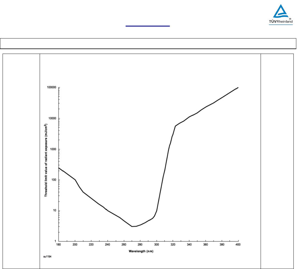
Report No.: 02072255.013 ATTACHMENT 1
National Differences
IEC 61010-1 and/or EN 61010-1
Attachment 1 to MS-0005049 Page 99 of 123 Version 2.0
Figure
DVC.2.1.1
[D2]
Figure DVC.2.1.1 – Threshold limit values (TLV) for ultraviolet radiation
N/A
Report No.: 02072255.013 ATTACHMENT 1
National Differences
IEC 61010-1 and/or EN 61010-1
Attachment 1 to MS-0005049 Page 100 of 123 Version 2.0
Table
DVC.2.1.1
[D2]
Table DVC.2.1.1 – Ultraviolet radiation exposure TLV and spectral weighting function
Wavelength (nm)
TLV (mJ/cm
2
)
Relative spectral effectiveness, Sλ
180
250
0,012
190
160
0,019
200
100
0,030
205
59
0,051
210
40
0,075
215
32
0,095
220
25
0,120
225
20
0,150
230
16
0,190
235
13
0,240
240
10
0,300
245
8,3
0,360
250
7,0
0,430
254 †
6,0
0,500
255
5,8
0,520
260
4,6
0,650
265
3,7
0,810
270
3,0
1,000
275
3,1
0,960
280 †
3,4
0,880
285
3,9
0,770
290
4,7
0,640
295
5,6
0,540
297 †
6,5
0,460
300
10
0,300
303 †
25
0,120
305
50
0,060
308
120
0,026
310
200
0,015
313 †
500
0,006
315
1 000
0,003
316
1 300
0,0024
317
1 500
0,0020
318
1 900
0,0016
319
2 500
0,0012
320
2900
0,0010
322
4 500
0,00067
323
5 600
0,00054
325
6 000
0,00050
328
6 800
0,00044
330
7 300
0,00041
333
8 100
0,00037
335
8 800
0,00034
340
11 000
0,00028
345
13 000
0,00024
350
15 000
0,00020
355
19 000
0,00016
360
23 000
0,00013
365 †
27 000
0,00011
370
32 000
0,000093
375
39 000
0,000077
380
47 000
0,000064
385
57 000
0,000053
390
68 000
0,000044
395
83 000
0,000036
400
100 000
0,000030
† Emission lines of a mercury discharge spectrum.
N/A

Report No.: 02072255.013 ATTACHMENT 1
National Differences
IEC 61010-1 and/or EN 61010-1
Attachment 1 to MS-0005049 Page 101 of 123 Version 2.0
c) For broad-spectrum or multi-peak sources, the
TLV for exposure of the unprotected skin or eye
should be calculated based on an effective weighting
formula:
E
eff
= Σ (E
λ
S
λ
∆λ)
Where
E
eff
is the effective irradiance relative to a monochro-
matic source at 270nm in mW/cm
2
[mJ/(s•cm
2
)];
E
λ
is the spectral irradiance in W/(cm
2
•nm);
S
λ
is the relative spectral effectiveness (unitless);
∆λ is the band width in nm.
The result of the calculation, E
eff
, should then be ei-
ther applied to Table DVC.2.1.2 or should be used in
the following calculation:
Exposure time TLV = 3 (mJ/cm
2
)/E
eff
(where E
eff
is in mW/cm
2
)
See above N/A
Table
DVC.2.1.2
[D2]
Table DVC.2.1.2 – Permissible ultraviolet exposures
Effective irradiance, E
eff
(mW/cm
2
)
Duration of exposure per day
0,0001
8 h
0,0002
4 h
0,0004
2 h
0,0008
1 h
0,0017
30 min
0,0033
15 min
0,005
10 min
0,01
5 min
0,05
1 min
0,1
30 s
0,3
10 s
3
1 s
6
0,5 s
30
0,1 s
N/A
d) For most white-light sources and all open arcs, the
weighting of spectral irradiance between 200 and 315
nm should suffice to determine the effective irradi-
ance.
See above N/A
- specialized UV sources designed to emit UV-A radi-
ation would normally require spectral weighting from
315 to 400 nm.
N/A
All of the preceding TLVs for UV energy apply to
sources which subtend an angle less than 80°.
See above N/A
Sources which subtend a greater angle need to be
measured only over an angle of 80°.
See above N/A

Report No.: 02072255.013 ATTACHMENT 1
National Differences
IEC 61010-1 and/or EN 61010-1
Attachment 1 to MS-0005049 Page 102 of 123 Version 2.0
NOTE 1 Conditioned (tanned) individuals can tolerate skin expo-
sure in excess of the TLV without erythemal effects. However,
such conditioning may not protect persons against skin cancer.
NOTE 2 Ozone (O
3
) is produced in air by sources emitting UV ra-
diation at wavelengths below 250 nm. Refer to the chemical sub-
stances TLV for ozone.
N/A
Annex DVD
[D2]
Equipment intended for permanent connection Not such an equipment N/A
DVD.1.1
[D2]
Equipment intended for permanent connection to the
mains shall have provision for connection of a wiring
system in accordance with ANSI/NFPA 70, NEC, with
CSA C22.1, CEC, Part I, or with both as appropriate,
and shall meet the requirements of DVD.2 to DVD.3,
as applicable.
See above N/A
DVD.1.2
[D2]
Conformity is checked by inspection, and as specified
in DVD.2 to DVD.3.
N/A
DVD.2
[D2]
Wiring TERMINALS and leads P
DVD.2.1.1
[D2]
PERMANENTLY CONNECTED EQUIPMENT shall
be provided with TERMINALS or leads for the con-
nection of conductors having an ampacity that, in ac-
cordance with the National Electrical Code and/or the
Canadian Electrical Code, Part I, is acceptable for the
equipment.
Not such an equipment N/A
DVD.2.1.2
[D2]
A TERMINAL or splice compartment shall be com-
plete.
No such compartment
N/A
The top, all sides, and a complete bottom shall be
provided when the equipment is shipped from the fac-
tory and shall enclose all field wiring TERMINALS
and splices intended to be made in the field. Equip-
ment with an ENCLOSURE that is complete need not
be provided with a separate compartment.
Not such an equipment N/A
DVD.2.1.3
[D2]
The TERMINAL or splice compartment in which
mains connections to PERMANENTLY CONNECTED
EQUIPMENT are made shall be located so that:
See above —
a) Internal wiring and electrical components are not
exposed to mechanical damage or strain while con-
nections are being made, and
N/A
b) These connections may be readily inspected after
the equipment is installed as intended.
N/A
DVD.2.1.4
[D2]
Conformity is checked by inspection N/A
DVD.2.2
[D2]
Wiring TERMINALS P

Report No.: 02072255.013 ATTACHMENT 1
National Differences
IEC 61010-1 and/or EN 61010-1
Attachment 1 to MS-0005049 Page 103 of 123 Version 2.0
DVD.2.2.1
[D2]
Wiring TERMINALS shall provide effective connec-
tions, by use of screws, nuts or equally effective de-
vices.
Approved terminal block used
P
DVD.2.2.2
[D2]
Wire binding screws are permitted as follows:
a) A No. 6 or M4 screw may be used to connect a 14
AWG (2,1 mm
2
) or smaller wire.
b) A No. 8 or M4.5 screw may be used to connect a
12 AWG (3,3 mm
2
) or smaller wire.
c) A No. 10 or M5 screw may be used to connect a
10 AWG (5,3 mm
2
) or smaller wire.
See above
—
DVD.2.2.3
[D2]
Conformity is checked by inspection. P
DVD.2.3.1
[D2]
The free length of a lead inside a wiring compartment
shall be at least 150 mm (6 inches).
No field wiring compartment N/A
DVD.2.3.2
[D2]
Conformity is checked by inspection. See above N/A
DVD.2.4
[D2]
TERMINAL and lead identification
Line, Neutral and GND are
properly identified by color,
terminals are marked
P
DVD.2.4.1
[D2]
TERMINALS and leads shall be identified in a man-
ner that will permit the equipment to be connected as
intended by the manufacturer.
See above P
DVD.2.4.2
[D2]
An identified neutral (grounded) conductor for equip-
ment with a mains-connected polarized convenience
receptacle
See above P
An identified neutral (grounded) conductor for equip-
ment with a mains-connected polarized lamp socket
No lamp socket N/A
NOTE A "grounded" supply conductor is one that is connected to
protective earth at some point in the building installation. It is
sometimes called the "neutral conductor".
See above N/A
DVD.2.4.3
[D2]
A wiring TERMINAL that is intended solely for con-
nection of the neutral (grounded) MAINS conductor
shall be readily distinguishable from all other
TERMINALS.
See DVD.2.4 above P
Constructed of, or plated with, metal that is substantial-
ly white in color or
Not used N/A
shall be clearly identified in some other manner, such
as on a wiring diagram permanently attached to the
equipment.
Clearly identified, wiring dia-
gram at bottom of the enclo-
sure
P
Clearly identified in some other manner, such as on a
wiring diagram permanently attached to the equipment
See above P

Report No.: 02072255.013 ATTACHMENT 1
National Differences
IEC 61010-1 and/or EN 61010-1
Attachment 1 to MS-0005049 Page 104 of 123 Version 2.0
DVD.2.4.4
[D2]
A lead intended solely for field wiring connection to
the neutral (grounded) MAINS conductor shall be
readily distinguishable from all other leads by means
of it being finished to show a white or gray color.
No field wiring connection N/A
DVD.2.4.5
[D2]
The protective grounding (earthing) TERMINAL shall
be marked in accordance with 5.1.5.2 (b)
PE Ground properly identified P
or marked "G," "GR," "GND," "GRD," "GROUND," or
"GROUNDING" or
See above N/A
provided with a green colored screwhead that is hex-
agonal, slotted, or both.
See above N/A
DVD.2.4.6
[D2]
A lead intended for field connection to the protective
grounding conductor shall be readily distinguishable
from all other leads by being finished to show a green
color with or without yellow stripes.
No field wiring connection N/A
DVD.2.4.7
[D2]
Conformity is checked by inspection. N/A
DVD.3
[D2]
ENCLOSURE requirements for conduit entry P
DVD.3.1
[D2]
An ENCLOSURE shall not pull apart or sustain dam-
age such as cracking and breaking, and
Complies, metal enclosure with
properly rated strain relief
bushing
P
knockouts shall remain in place when subjected to
the pulling, torque, and bending that is likely to occur.
See above, no know outs N/A
DVD.3.2
[D2]
ENCLOSURES having sheet metal members
Stamped sheet metal is 1.0mm
thick
P
Uncoated sheet steel enclosure is 0,81 mm thick min-
imum
See above P
Galvanized sheet steel enclosure is 0,86 mm thick
minimum
See above P
Aluminum sheet enclosure is 1,11 mm thick minimum Not used N/A
Copper or brass sheet enclosure is 1,09 mm thick min-
imum
Not used N/A
NOTE ENCLOSURES complying with ANSI/UL 50 are deemed to
comply with DVD.4.1 and DVD.4.2.
—
DVD.3.3
[D2]
An ENCLOSURE made either wholly or in part of in-
sulating material shall have an acceptable bonding
means to provide continuity of bonding between all
metallic conduits entering the ENCLOSURE.
Not used N/A
DVD.3.4
[D2]
Conformity is checked by inspection and by perform-
ing the applicable tests of DVD.4.
N/A

Report No.: 02072255.013 ATTACHMENT 1
National Differences
IEC 61010-1 and/or EN 61010-1
Attachment 1 to MS-0005049 Page 105 of 123 Version 2.0
DVD.4
[D2]
Conduit ENCLOSURE entry tests Complies, metal enclosure with
properly rated strain relief
bushing
P
DVD.4.1
[D2]
Conduit pull-out test
See above P
DVD.4.1.1
[D2]
The ENCLOSURE shall be suspended by a length of
rigid conduit installed in one wall of the ENCLOSURE
or mounted as intended in service, and a pulling force
of 890 N (200 lb) shall be applied
for 5 min to a length
of conduit installed in the opposite wall (or wall with
conduit entry if ENCLOSURE is mounted rather than
suspended).
Complies P
DVD.4.2
[D2]
Conduit torque test P
DVD.4.2.1
[D2]
The ENCLOSURE shall be securely mounted as in-
tended in service. A torque in accordance with table
DVD.4.2.1.1 shall be applied to a length of installed
conduit in a direction tending to tighten the connec-
tion. The lever arm shall be measured from the cen-
ter of the conduit.
Complies P
Table
DVD.4.2.1.1
[D2]
Table DVD.4.2.1.1 - Tightening torque for conduit
Trade size of conduit,
in
Tightening torque,
lb-in (N•m)
3/4 and smaller (end-of-line ENCLOSURE) 1
200 (22,6)
3/4 and smaller
800 (90,4)
1, 1-1/4, 1-1/2
1 000 (113)
2 and larger
1 600 (181)
1 An end-of-line ENCLOSURE is an ENCLOSURE that is intended to be connected
at the end of a run of conduit and has only one 3/4-in maximum trade size opening
for the connection of conduit.
—
DVD.4.3
[D2]
Bending P
DVD.4.3.1
[D2]
A length of conduit at least 300 mm (1 ft) long of the
intended size shall be installed:
Complies P
1) In the center of the largest unreinforced surface, or P
2) In a hub or an opening if provided as part of the
ENCLOSURE.
Not such an equipment N/A
Report No.: 02072255.013 ATTACHMENT 1
National Differences
IEC 61010-1 and/or EN 61010-1
Attachment 1 to MS-0005049 Page 106 of 123 Version 2.0
DVD.4.3.2
[D2]
The ENCLOSURE shall be securely mounted as in-
tended in service, but positioned so that the installed
conduit extends in a horizontal plane. A weight shall
be suspended from the end of the conduit to produce
the bending moment specified in Table DVD.4.3.2.1.
The magnitude of the weight shall be determined
from the equation:
W = (M - 0,5*C*L)/L, In which
W is the weight, in lb, to be hung at the end of
the conduit;
L is the length of the conduit, in inches, from
the wall of the ENCLOSURE to the point at
which the weight is suspended;
C is the weight of the conduit, in lb; and
M is the bending moment required in lb-in.
For the SI system of units, the equation is:
W = (0,1*M - 0,5*C*L)/L, In which
W and C are measured in kg;
M is measured in N•m; and
L is measured in m.
P
Table
DVD.4.3.2.1
[D2]
Table DVD.4.3.2.1 - Bending moment for conduit openings
Normal mounting plane
of
ENCLOSURE
surface(a)
Conduit size, in
Bending moment (b,c) N•m (lb-in)
Metallic conduit
Nonmetallic conduit
Horizontal
All
34
(300)
34
(300)
Vertical
1/2 – 3/4
34
(300)
34
(300)
1 and larger
68
(600)
34
(300)
P
DVD.4.3.3
[D2]
If the ENCLOSURE surface can be installed in either
a horizontal or a vertical plane, the vertical bending
moment value shall be used.
Only horizontal positioning N/A
DVD.4.3.4
[D2]
The test procedure may be terminated prior to attain-
ing the values specified if the deflection of the conduit
exceeds 250 mm (10 in) for a 3,05 m (10 ft) length of
conduit.
No deflection N/A
DVD.4.3.5
[D2]
For an end-of-line ENCLOSURE as defined in Table
DVD.4.2.1.1, the bending moment shall be 17,0 N•m
(150 lb-in).
N/A
DVD.4.4
[D2]
Knockouts Not used N/A
DVD.4.4.1
[D2]
A knockout shall be subjected to a force of 89 N (20
lb) applied at right angles by means of a mandrel with
a 6,4-mm (1/4-in) diameter flat end. The mandrel
shall be applied at the point most likely to cause
movement of the knockout.
See above N/A

Report No.: 02072255.013 ATTACHMENT 1
National Differences
IEC 61010-1 and/or EN 61010-1
Attachment 1 to MS-0005049 Page 107 of 123 Version 2.0
New Bibliog-
raphy BIBDV
[D2]
Add the following bibliographic references:
ACIGH 7DOC-656, Ultraviolet Radiation: TLV - Phys-
ical Agents 7th Edition Documentation
ASME-BPVC, ASME Boiler and Pressure Vessel
Code
ANSI/UL 1581 Reference Standard for Electrical
Wires, Cables, and Flexible Cords
CAN/CSA C22.2 No. 0.3, Test methods for electrical
wires and cables
R.S.C. 1985, Canadian Radiation Emitting Devices
Act
21 CFR 1020, USA Code of Federal Regulations, Ti-
tle 21, Subpart J, Part 1020: Performance Standards
for Ionizing Radiation Emitting Products
21 CFR 1040, USA Code of Federal Regulations, Ti-
tle 21, Subpart J, Part 1040: Performance Standards
for Light-Emitting Products
INFORMATIVE

Report No.: 02072255.013 ATTACHMENT 2
Photographs
IEC 61010-1 and/or EN 61010-1
Page 108 of 123

Report No.: 02072255.013 ATTACHMENT 2
Photographs
IEC 61010-1 and/or EN 61010-1
Page 109 of 123

Report No.: 02072255.013 ATTACHMENT 2
Photographs
IEC 61010-1 and/or EN 61010-1
Page 110 of 123

Report No.: 02072255.013 ATTACHMENT 2
Photographs
IEC 61010-1 and/or EN 61010-1
Page 111 of 123

Report No.: 02072255.013 ATTACHMENT 2
Photographs
IEC 61010-1 and/or EN 61010-1
Page 112 of 123

Report No.: 02072255.013 ATTACHMENT 2
Photographs
IEC 61010-1 and/or EN 61010-1
Page 113 of 123

Report No.: 02072255.013 ATTACHMENT 2
Photographs
IEC 61010-1 and/or EN 61010-1
Page 114 of 123

Report No.: 02072255.013 ATTACHMENT 3
Transformer Schematic and Specifications
IEC 61010-1 and/or EN 61010-1
Page 115 of 123

Report No.: 02072255.013 ATTACHMENT 3
Transformer Schematic and Specifications
IEC 61010-1 and/or EN 61010-1
Page 116 of 123

Report No.: 02072255.013 ATTACHMENT 3
Transformer Schematic and Specifications
IEC 61010-1 and/or EN 61010-1
Page 117 of 123

Report No.: 02072255.013 ATTACHMENT 3
Transformer Schematic and Specifications
IEC 61010-1 and/or EN 61010-1
Page 118 of 123

Report No.: 02072255.013 ATTACHMENT 3
Transformer Schematic and Specifications
IEC 61010-1 and/or EN 61010-1
Page 119 of 123

Report No.: 02072255.013 ATTACHMENT 3
Transformer Schematic and Specifications
IEC 61010-1 and/or EN 61010-1
Page 120 of 123

Report No.: 02072255.013 ATTACHMENT 3
Transformer Schematic and Specifications
IEC 61010-1 and/or EN 61010-1
Page 121 of 123

Report No.: 02072255.013 ATTACHMENT 3
Transformer Schematic and Specifications
IEC 61010-1 and/or EN 61010-1
Page 122 of 123

Report No.: 02072255.013 ATTACHMENT 3
Transformer Schematic and Specifications
IEC 61010-1 and/or EN 61010-1
Page 123 of 123
